EP1557640A2 - Part length measurement technique using two or three proximity sensors - Google Patents
Part length measurement technique using two or three proximity sensors Download PDFInfo
- Publication number
- EP1557640A2 EP1557640A2 EP04028663A EP04028663A EP1557640A2 EP 1557640 A2 EP1557640 A2 EP 1557640A2 EP 04028663 A EP04028663 A EP 04028663A EP 04028663 A EP04028663 A EP 04028663A EP 1557640 A2 EP1557640 A2 EP 1557640A2
- Authority
- EP
- European Patent Office
- Prior art keywords
- sensor
- sensors
- time segment
- parts
- length
- Prior art date
- Legal status (The legal status is an assumption and is not a legal conclusion. Google has not performed a legal analysis and makes no representation as to the accuracy of the status listed.)
- Withdrawn
Links
- 238000000691 measurement method Methods 0.000 title description 4
- 238000000034 method Methods 0.000 claims abstract description 32
- 238000005259 measurement Methods 0.000 abstract description 23
- 238000012545 processing Methods 0.000 description 3
- 238000009434 installation Methods 0.000 description 2
- 238000004519 manufacturing process Methods 0.000 description 2
- 238000005070 sampling Methods 0.000 description 2
- 230000003068 static effect Effects 0.000 description 2
- 238000012360 testing method Methods 0.000 description 2
- 238000013459 approach Methods 0.000 description 1
- 230000005465 channeling Effects 0.000 description 1
- 238000004891 communication Methods 0.000 description 1
- 230000001419 dependent effect Effects 0.000 description 1
- 230000007774 longterm Effects 0.000 description 1
- 238000000926 separation method Methods 0.000 description 1
Images


Classifications
-
- G—PHYSICS
- G01—MEASURING; TESTING
- G01B—MEASURING LENGTH, THICKNESS OR SIMILAR LINEAR DIMENSIONS; MEASURING ANGLES; MEASURING AREAS; MEASURING IRREGULARITIES OF SURFACES OR CONTOURS
- G01B11/00—Measuring arrangements characterised by the use of optical techniques
- G01B11/02—Measuring arrangements characterised by the use of optical techniques for measuring length, width or thickness
- G01B11/04—Measuring arrangements characterised by the use of optical techniques for measuring length, width or thickness specially adapted for measuring length or width of objects while moving
-
- G—PHYSICS
- G01—MEASURING; TESTING
- G01B—MEASURING LENGTH, THICKNESS OR SIMILAR LINEAR DIMENSIONS; MEASURING ANGLES; MEASURING AREAS; MEASURING IRREGULARITIES OF SURFACES OR CONTOURS
- G01B11/00—Measuring arrangements characterised by the use of optical techniques
- G01B11/02—Measuring arrangements characterised by the use of optical techniques for measuring length, width or thickness
- G01B11/04—Measuring arrangements characterised by the use of optical techniques for measuring length, width or thickness specially adapted for measuring length or width of objects while moving
- G01B11/043—Measuring arrangements characterised by the use of optical techniques for measuring length, width or thickness specially adapted for measuring length or width of objects while moving for measuring length
-
- G—PHYSICS
- G01—MEASURING; TESTING
- G01B—MEASURING LENGTH, THICKNESS OR SIMILAR LINEAR DIMENSIONS; MEASURING ANGLES; MEASURING AREAS; MEASURING IRREGULARITIES OF SURFACES OR CONTOURS
- G01B21/00—Measuring arrangements or details thereof, where the measuring technique is not covered by the other groups of this subclass, unspecified or not relevant
- G01B21/02—Measuring arrangements or details thereof, where the measuring technique is not covered by the other groups of this subclass, unspecified or not relevant for measuring length, width, or thickness
- G01B21/06—Measuring arrangements or details thereof, where the measuring technique is not covered by the other groups of this subclass, unspecified or not relevant for measuring length, width, or thickness specially adapted for measuring length or width of objects while moving
Definitions
- the invention pertains to the field of measurement of the length of a part. More particularly, the invention pertains to part measurement technique using two or more proximity sensors.
- multiple sensors wherein at least one sensor needs to be adjusted in relation to the other sensors for measuring a part having a specific length.
- a method for determining the range of a dimensional parameter of a multiplicity of members includes the steps of: providing at least two sensors; fixing a set constant distances ( ⁇ 1) between the sensors such that the relative distances between sensors are fixed and free from adjustment; and measuring the dimensional parameter based upon a ratio ( ⁇ t 2 / ⁇ t 1 ) of a first time segment ( ⁇ t 1 ) and a second time segment ( ⁇ t 2 ), whereby no adjustment of the relative distance between sensors is required.
- a method for determining the range of a dimensional parameter of a multiplicity of members includes the steps of: providing at least two sensors including a first sensor and a second sensor; fixing a set of constant distances ( ⁇ 1) between the sensors including at least one distance between the first sensor and the second sensor, such that the relative distances between sensors are fixed and free from adjustment during the sensors' sensing operation; and measuring the dimensional parameter based upon a ratio ( ⁇ t 2 / ⁇ t 1 ) of a first time segment ( ⁇ t 1 ) and a second time segment ( ⁇ t 2 ), whereby no adjustment of the relative distance between sensors is required.
- a method for determining the range of a dimensional parameter of a multiplicity of members includes: providing two sensors, including a first sensor and a second sensor; fixing a constant distance ( ⁇ 1) between the a first sensor and a second sensor such that the relative distances between sensors are fixed and free from adjustment; moving the multiplicity of members relative to the two sensors; predetermining a point on each member; recording a first time segment ( ⁇ t 1 ); recording a second time segment ( ⁇ t 2 ); and computing a dimension of the member.
- a part measurement system 10 is shown.
- the purpose of the system is to quickly or efficiently measure a multiplicity of parts which comprises desired parts as well as undesirable parts.
- a multiplicity of parts 12 and some undesired foreign parts 14 are provided for measurement.
- the parts 12 and undesired foreign parts may be movably traveling through a channel 16 which form a physically constricting means for channeling parts 12 and parts 14 for desired measurement.
- channel 16 may not be needed in that parts 12 and parts 14 may be free falling from one area to another area and during the free falling period be measured by system 10.
- Foreign parts 14 are parts inadvertently or undesirably got mixed together with parts 12. This mixing together may include production error of parts.
- the variations of parts 12 and parts 14 can be very small in the context of the total dimension of parts 12 and parts 14 respectively.
- Foreign parts 14 are parts which need to be first identified and preferably later taken out according to the teachings of the present invention.
- a plurality of sensors including first sensor 18 and second sensor 20 are stably positioned in relation to the parts including multiplicity of parts 12 and some undesired foreign parts 14, which move in relation to the sensors, i.e. first sensor 18 and second sensor 20.
- a controller 22 is coupled to the sensors for processing the sensed information.
- stably positioned it means that the distance 28 between first sensor 18 and second sensor 20 is a constant at least during the parts measurement process or period. In other words, distance 28 may be adjustable, but during the parts measurement distance 28 is fixed or is a constant.
- This adjustability is desirable in that for a measurement of a different part dimension, it is preferable to adjust or change distance 28 to correspond to the different part dimension.
- distance 28 can be adjusted to be substantially identical to the pin length in order to have a more efficient measurement.
- the distance 28 is not critical to the function of the system. That is what makes the technique of the present invention different from other methods like the one described in the Background section of the present invention. It needs to be stressed that in the description supra, the positioning of the sensors need only be approximate for this technique to work. In other words, absolute accurate positioning of the distance between the sensors are not required. Of course, proper positioning can increase the accuracy and repeatability but that is only required for very special situations. In its basic form this technique is independent of the sensor location relative to each other.
- a set of receivers may be provided for receiving the sensor signals coming from the sensors. Note that only two sensors i.e. sensor 18 and sensor 20, with their respective receivers, i.e. receiver 18a and receiver 20a are shown. The set of receivers and their sensors are each coupled to the microcontroller 22 respectively. Note that receivers such as receiver 18a and receiver 20a may not be needed in the present invention. For example, when the sensors are reflective sensors, receivers may not be needed.
- the distance between the parts i.e. gap 26
- the distance between the parts is irrelevant to the function of the technique of the present invention. It is the presence, not the absence of parts as a single part passes the sensors that are being sensed.
- the sensor therein may be directed to sense at only a predetermined direction. In other words, all the sensors involved do not need to be focused upon point 24.
- a non-focused system is depicted. It is noted that by “focused”, it is meant that the sensors have their respective sensing points as one identical point. In other words, by “focused”, it is meant that the sensors sensing directions are focused at a single point. For example, at the instant as shown in Fig.1, sensor 18 has its sensing rays 18b blocked by pin 12 such that receiver 18a cannot received communication coming from sensor 18. At this juncture, a different signal (or first signal) is fed to microprocessor 22.
- system 10 is disposed to know information relating to the length of pin 12 or pin 14, and thereby processing the same according to the teachings of the present invention.
- One way to process the information is to record the time periods that have elapsed with regard to the sensors, be they first sensor 18, second sensor 20 or third or fourth sensors (not shown) if required.
- sensor 20 may have a built in receiver (not shown) which performs similar functions as receiver 20a in feeding information back to microcontroller 22.
- Sensor 18 may constitute substantially identical receiver therein for similar purposes.
- any distance between any two points with one point on one sensor and the other point on the other sensor is a constant.
- Distance 28 is a constant.
- the present invention contemplates a set of sensors for sensing parts 12, 14 in which the sensors are positioned such that no relative movement of any sensor is required.
- a method of processing the information sensed according to Fig. 1 is shown. More specifically, a set of measured signals for proposed two proximity switch length measurement technique is shown.
- ⁇ l is defined as the distance between the sensors switches, such as distance 28 of Figure 1.
- ⁇ l is a known value in that it is fixed at least during measurement. Therefore, we can calculate the pin velocity: wherein ⁇ t 1 is the time segment from a point in which the length of a part (such as a pin) entering a first sensor range until the point is sensed by a second sensor.
- ⁇ t 1 is the time segment from a point in which the length of a part (such as a pin) entering a first sensor range until the point is sensed by a second sensor.
- V pin is dependent upon the variations of ⁇ t 1 .
- ⁇ t 2 is the time segment required for the length of a part (such as a pin) to pass a single sensor, be it the first sensor18 , the second sensor 20, or other extra sensors.
- velocity of the moving parts such as the pins may not be a constant. In other words, the velocity may a variable or function that change with the passing of time. If this is the case, some adjustments are required. The adjustment includes changing the ratio ( ⁇ t 2 / ⁇ t 1 ).
- high velocity is an important feature taking into consideration by the present invention. A working definition of "high" velocity is that the speed at which the parts subject to measurement pass a sensor (or sensors) so fast that effective measurements using known means are in sufficient. For example, a "low" velocity, one may merely use a single sensor for measurement. The sensor may even be the naked eye of humans.
- the measured pin length is proportional to the ratio ( ⁇ t 2 / ⁇ t 1 ),
- a third sensor 21 is added, which in turn has sensing ray 21b directed at pins for sensing variations thereto.
- a receiver 21 a may be provided for receiving ray 21 a from sensor 21.
- sensor 21 may have a built in receiver (not shown) which performs similar functions as receiver 21 a in feeding information back to microcontroller 22.
- Sensor 21 may sense parts via a focused sense line 21 a that being focused upon a single point on the moving parts 12, 14.
- the single point 24 is also the point being focused by sensor 18 and sensor 20.
- sensor 21 may have a non-focused sensing line 21b.
- sensor 21 has a fixed position thereby its relative distance to sensor 18 and sensor 20 is a pair of constants respectively.
- distance 28a or distance 28b is respectively of a fixed value or constants. It is noted that in a three dimensional condition, the sensors may not be mounted along a straight line. That is to say, the value of distance 28b may not be the sum total of the values of distance 28 and distance 28a.
- each sensor has its own ⁇ t 2 and ⁇ t 1 .
- ⁇ t 2 the ratio of the ratio ( ⁇ t 2 / ⁇ t 1 ) and can produce a more robust approach to length sensing. This is especially true when the parts are changing velocity over the sensor separation length (28, 28b).
- Fig. 3b which shows the signals available from the 3 sensor technique and the additional available ( ⁇ t) values are available for alternate calculations.
- two sensors are theoretically sufficient for the present invention.
- the distance between the two sensors is preferably set to equal the parts length subject to measurement.
- parts length subject to measurement cannot always be the same. Further factors involved are the error in measurement inherent in any sensor, the velocity of the movement of the parts subject to measurement, and the length or dimensional difference between the desired parts and the undesired parts, etc. Therefore, more than two sensors may be introduced thereby more parameters can be measured and thereby provided more row data for a improved accuracy in the measurement of the present invention.
- a diagrammatic depiction of a pin length selection system is shown.
- Parts to be tested pass through channel 16.
- the parts can be desired parts 12 as well as undesired parts 14.
- the parts, while in channel 16, are sensed by sensor unit 30, which may include first sensor 18, and second sensor 20, or other sensors (not shown).
- Actuators such as first actuator 32 and second actuator 34 are provided for selectively collecting desired parts 12 in a pass container and parts 14 in a fail container.
- First actuator 32 and second actuator 34 each respectively receives command from microprocessor 22 and is informationally coupled thereto.
- the hardware involved includes
- Fig. 5 shows the prototype installation on a V-track that is automatically fed from a vibrating bowl feeder.
- a microcomputer was programmed to interpret the sensor output and calculate the ( ⁇ t 2 / ⁇ t 1 ,) ratio.
- Fig. 6 shows sorting program in operation. At this time testing is ongoing on this technique but initial results indicate that the method is quite accurate with proper sensor orientation and setup. As discussed supra, the fact that sensor positioning is not critical to the basic function of this system. of course better results can be achieved by modifying the sensor position but it is also found that at high speed, repeatable sensors are better and that proper part presentation can also improve the accuracy and repeatability. By way of an example, repeatability of ⁇ 0.0005" has been demonstrated for pin speeds up to 35 inches per second. Additional testing will consider throughput capabilities and long term durability of the system for offline pin sorting in the production environment. Note the graphic window therein for easy user determination.
- the present invention contemplates that any number of members having a physical dimension can be measured using the method described supra. Of course a means need be provided to move the members relative to at least two sensors.
Landscapes
- Physics & Mathematics (AREA)
- General Physics & Mathematics (AREA)
- Length Measuring Devices With Unspecified Measuring Means (AREA)
Abstract
The invention pertains to the field of measurement of the length of a
part, and more particularly, using two or more proximity sensors.
Therefore a method for determining the range of a dimensional parameter of a multiplicity of
members is provided. The method includes the steps of: providing at least two
sensors; fixing a set constant distances between the sensors such that the relative
distances between sensors are fixed and free from adjustment; and measuring the
dimensional parameter based upon a ratio of a first time segment and a
second time segment, whereby no adjustment of the relative distance between
sensors is required.
Description
- The invention pertains to the field of measurement of the length of a part. More particularly, the invention pertains to part measurement technique using two or more proximity sensors.
- It is known to use a single sensor for measuring the length of a part. US patent 5,430,665 teaches an apparatus and method for measuring length of moving elongated object.
- Further, it is also known to use multiple sensors, wherein at least one sensor needs to be adjusted in relation to the other sensors for measuring a part having a specific length. For example, it is known to use multiple sensors in a line to measure length, in which system relies on precise positioning to measure length.
- However, for the above types of known measurements, the sampling rates of even the fastest of these systems was not adequate to dynamically measure the length of a moving pin. For accurate measurements the pins had to be held static momentarily. Since the minimum rates were determined to be 10 or more parts per second, the concept of static sampling is not practical. Because no cost effective off-the-shelf sensor or sensor systems were capable of measuring pin length within the tolerances required and at the rates required, therefore a new measuring method or system is needed.
- A method for determining the length of a multiplicity of individual parts using at least 2 sensors where the relative distance between the 2 sensors is fixed in that the relative distance is not adjusted during the determining step.
- A method for determining the range of a dimensional parameter of a multiplicity of members is provided. The method includes the steps of: providing at least two sensors; fixing a set constant distances (Δ1) between the sensors such that the relative distances between sensors are fixed and free from adjustment; and measuring the dimensional parameter based upon a ratio (Δt2/ Δt1) of a first time segment (Δt1) and a second time segment (Δt2), whereby no adjustment of the relative distance between sensors is required.
- A method for determining the range of a dimensional parameter of a multiplicity of members is provided. The method includes the steps of: providing at least two sensors including a first sensor and a second sensor; fixing a set of constant distances (Δ1) between the sensors including at least one distance between the first sensor and the second sensor, such that the relative distances between sensors are fixed and free from adjustment during the sensors' sensing operation; and measuring the dimensional parameter based upon a ratio (Δt2/ Δt1) of a first time segment (Δt1) and a second time segment (Δt2), whereby no adjustment of the relative distance between sensors is required.
- A method for determining the range of a dimensional parameter of a multiplicity of members is provided. The method includes: providing two sensors, including a first sensor and a second sensor; fixing a constant distance (Δ1) between the a first sensor and a second sensor such that the relative distances between sensors are fixed and free from adjustment; moving the multiplicity of members relative to the two sensors; predetermining a point on each member; recording a first time segment (Δt1); recording a second time segment (Δt2); and computing a dimension of the member.
-
- Fig. 1 shows a part measurement system of the present invention.
- Fig. 2 shows a set of measured signals for proposed two sensor or proximity switch length measurement technique of the present invention.
- Fig. 3 shows an alternative embodiment of the present invention.
- Fig. 3b shows the signals available from the 3 sensor technique.
- Fig. 4 shows a diagrammatic depiction of a pin length selection system.
- Fig.5 shows the prototype installation on a V-track that is automatically fed from a vibrating bowl feeder.
- Fig. 6 shows sorting program in operation.
-
- This section includes the descriptions of the present invention including the preferred embodiment of the present invention for the understanding of the same. It is noted that the embodiments are merely describing the invention. The claims section of the present invention defines the boundaries of the property right conferred by law.
- Referring to Fig. 1, a
part measurement system 10 is shown. The purpose of the system is to quickly or efficiently measure a multiplicity of parts which comprises desired parts as well as undesirable parts. As shown, a multiplicity ofparts 12 and some undesiredforeign parts 14 are provided for measurement. Theparts 12 and undesired foreign parts may be movably traveling through achannel 16 which form a physically constricting means for channelingparts 12 andparts 14 for desired measurement. Note thatchannel 16 may not be needed in thatparts 12 andparts 14 may be free falling from one area to another area and during the free falling period be measured bysystem 10.Foreign parts 14 are parts inadvertently or undesirably got mixed together withparts 12. This mixing together may include production error of parts. As can be seen, the variations ofparts 12 andparts 14 can be very small in the context of the total dimension ofparts 12 andparts 14 respectively. -
Foreign parts 14 are parts which need to be first identified and preferably later taken out according to the teachings of the present invention. A plurality of sensors includingfirst sensor 18 andsecond sensor 20 are stably positioned in relation to the parts including multiplicity ofparts 12 and some undesiredforeign parts 14, which move in relation to the sensors, i.e.first sensor 18 andsecond sensor 20. Acontroller 22 is coupled to the sensors for processing the sensed information. By stably positioned, it means that thedistance 28 betweenfirst sensor 18 andsecond sensor 20 is a constant at least during the parts measurement process or period. In other words,distance 28 may be adjustable, but during theparts measurement distance 28 is fixed or is a constant. This adjustability is desirable in that for a measurement of a different part dimension, it is preferable to adjust or changedistance 28 to correspond to the different part dimension. By way of an example, if a pin length is the thing subject to measurement,distance 28 can be adjusted to be substantially identical to the pin length in order to have a more efficient measurement. However, it needs to be made clear that a key provision of this technique is that thedistance 28 is not critical to the function of the system. That is what makes the technique of the present invention different from other methods like the one described in the Background section of the present invention. It needs to be stressed that in the description supra, the positioning of the sensors need only be approximate for this technique to work. In other words, absolute accurate positioning of the distance between the sensors are not required. Of course, proper positioning can increase the accuracy and repeatability but that is only required for very special situations. In its basic form this technique is independent of the sensor location relative to each other. - This is especially true when the multiplicities of pins are moving at high speed. For detailed discussion, see infra.
- A set of receivers may be provided for receiving the sensor signals coming from the sensors. Note that only two sensors i.e.
sensor 18 andsensor 20, with their respective receivers,i.e. receiver 18a andreceiver 20a are shown. The set of receivers and their sensors are each coupled to themicrocontroller 22 respectively. Note that receivers such asreceiver 18a andreceiver 20a may not be needed in the present invention. For example, when the sensors are reflective sensors, receivers may not be needed. - It is noted that the distance between the parts (i.e. gap 26) is irrelevant to the function of the technique of the present invention. It is the presence, not the absence of parts as a single part passes the sensors that are being sensed.
- In most sensor systems, the sensor therein may be directed to sense at only a predetermined direction. In other words, all the sensors involved do not need to be focused upon
point 24. For example, as indicated by the dottedline sensor 18 has itssensing rays 18b blocked bypin 12 such thatreceiver 18a cannot received communication coming fromsensor 18. At this juncture, a different signal (or first signal) is fed tomicroprocessor 22. when a sensor can communicate with its receiver such as shown in the figure with regard tosensor 20 in whichsensing rays 20b is received byreceiver 18a due to the crevice or thejunction 26 between pins (in this example, between two pin 12), a second signal is fed tomicroprocessor 22. As such,system 10 is disposed to know information relating to the length ofpin 12 orpin 14, and thereby processing the same according to the teachings of the present invention. One way to process the information is to record the time periods that have elapsed with regard to the sensors, be theyfirst sensor 18,second sensor 20 or third or fourth sensors (not shown) if required. - Alternatively,
sensor 20 may have a built in receiver (not shown) which performs similar functions asreceiver 20a in feeding information back tomicrocontroller 22.Sensor 18 may constitute substantially identical receiver therein for similar purposes. - Furthermore, the positioning between the sensors is fixed and independent of the part length. In other words, any distance between any two points with one point on one sensor and the other point on the other sensor is a constant. There exists a fixed
distance 28 betweensensor 18 andsensor 20.Distance 28 is a constant. The present invention contemplates a set of sensors for sensingparts - Referring to Fig. 2, a method of processing the information sensed according to Fig. 1 is shown. More specifically, a set of measured signals for proposed two proximity switch length measurement technique is shown. Δl is defined as the distance between the sensors switches, such as
distance 28 of Figure 1. Further, Δl is a known value in that it is fixed at least during measurement. Therefore, we can calculate the pin velocity:wherein Δt1 is the time segment from a point in which the length of a part (such as a pin) entering a first sensor range until the point is sensed by a second sensor. As can be seen, since Δl is a known value, Vpin is dependent upon the variations of Δt1.
- Using this velocity we arrive at or can calculate the pin length, lpin as:wherein Δt2 is the time segment required for the length of a part (such as a pin) to pass a single sensor, be it the first sensor18 , the
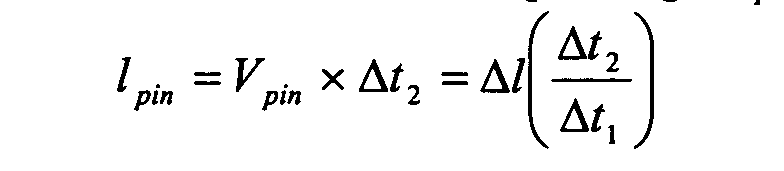
second sensor 20, or other extra sensors. - It is noted that velocity of the moving parts such as the pins may not be a constant. In other words, the velocity may a variable or function that change with the passing of time. If this is the case, some adjustments are required. The adjustment includes changing the ratio (Δt2 /Δt1). It is noted that high velocity is an important feature taking into consideration by the present invention. A working definition of "high" velocity is that the speed at which the parts subject to measurement pass a sensor (or sensors) so fast that effective measurements using known means are in sufficient. For example, a "low" velocity, one may merely use a single sensor for measurement. The sensor may even be the naked eye of humans.
- Since the value of Δ/ is fixed, the measured pin length is proportional to the ratio
- Referring to Fig. 3, an
alternative embodiment 10a of the present invention is shown. In addition to the elements shown in Fig. 1, athird sensor 21 is added, which in turn hassensing ray 21b directed at pins for sensing variations thereto. Areceiver 21 a may be provided for receivingray 21 a fromsensor 21. Alternatively,sensor 21 may have a built in receiver (not shown) which performs similar functions asreceiver 21 a in feeding information back tomicrocontroller 22. - Additionally, a
third sensor 21 is provided.Sensor 21 may sense parts via afocused sense line 21 a that being focused upon a single point on the movingparts single point 24 is also the point being focused bysensor 18 andsensor 20. Alternatively,sensor 21 may have anon-focused sensing line 21b. - During measurement,
sensor 21 has a fixed position thereby its relative distance tosensor 18 andsensor 20 is a pair of constants respectively. In other words,distance 28a ordistance 28b is respectively of a fixed value or constants. It is noted that in a three dimensional condition, the sensors may not be mounted along a straight line. That is to say, the value ofdistance 28b may not be the sum total of the values ofdistance 28 anddistance 28a. - As can be seen, for three or more sensor systems such as
system 10a, the relationships between information sensed by each sensor are more elaborate. In other words, each sensor has its own Δt2 and Δt1. For any one of the more than three sensor, instead of only one other sensor for correlation purpose, more than one sensor is involved. As can be seen, this allows for multiple and alternate calculations of the ratio (Δt2/Δt1) and can produce a more robust approach to length sensing. This is especially true when the parts are changing velocity over the sensor separation length (28, 28b). - For example, in Fig. 3b which shows the signals available from the 3 sensor technique and the additional available (Δt) values are available for alternate calculations.
- It is noted that in the ideal condition, two sensors are theoretically sufficient for the present invention. The distance between the two sensors is preferably set to equal the parts length subject to measurement. However, due to the fixed distance nature of the present invention, parts length subject to measurement cannot always be the same. Further factors involved are the error in measurement inherent in any sensor, the velocity of the movement of the parts subject to measurement, and the length or dimensional difference between the desired parts and the undesired parts, etc. Therefore, more than two sensors may be introduced thereby more parameters can be measured and thereby provided more row data for a improved accuracy in the measurement of the present invention.
- Referring to Fig. 4, a diagrammatic depiction of a pin length selection system is shown. Parts to be tested pass through
channel 16. Note that the parts can be desiredparts 12 as well asundesired parts 14. The parts, while inchannel 16, are sensed bysensor unit 30, which may includefirst sensor 18, andsecond sensor 20, or other sensors (not shown). Actuators such asfirst actuator 32 andsecond actuator 34 are provided for selectively collecting desiredparts 12 in a pass container andparts 14 in a fail container.First actuator 32 andsecond actuator 34 each respectively receives command frommicroprocessor 22 and is informationally coupled thereto. The following is an example that evaluates several variations on this concept of the present invention. The hardware involved includes - Fig. 5 shows the prototype installation on a V-track that is automatically fed from a vibrating bowl feeder. A microcomputer was programmed to interpret the sensor output and calculate the (Δt2 /Δt1,) ratio.
- Fig. 6 shows sorting program in operation. At this time testing is ongoing on this technique but initial results indicate that the method is quite accurate with proper sensor orientation and setup. As discussed supra, the fact that sensor positioning is not critical to the basic function of this system. of course better results can be achieved by modifying the sensor position but it is also found that at high speed, repeatable sensors are better and that proper part presentation can also improve the accuracy and repeatability. By way of an example, repeatability of ±0.0005" has been demonstrated for pin speeds up to 35 inches per second. Additional testing will consider throughput capabilities and long term durability of the system for offline pin sorting in the production environment. Note the graphic window therein for easy user determination.
- The present invention contemplates that any number of members having a physical dimension can be measured using the method described supra. Of course a means need be provided to move the members relative to at least two sensors.
- Accordingly, it is to be understood that the embodiments of the invention herein described are merely illustrative of the application of the principles of the invention. References herein to details of the illustrated embodiments are not intended to limit the scope of the claims, which themselves recite those features regarded as essential to the invention.
Claims (7)
- A method for determining the range of a dimensional parameter of a multiplicity of members, comprising:providing at least two sensors including a first sensor and a second sensor;fixing a set of constant distances (Δ1) between the sensors including at least one distance between the first sensor and the second sensor, such that the relative distances between sensors are fixed and free from adjustment during the sensors' sensing operation; andmeasuring the dimensional parameter based upon a ratio (Δt2/ Δt1) of a first time segment (Δt1) and a second time segment (Δt2), whereby no adjustment of the relative distance between sensors is required.
- The method of claim 1, wherein the first time segment (Δt1) is a duration of time starting when a first sensor starts recording as a fixed point of a member among the multiplicity of members, and ending when a second sensor starts recording as the fixed point of the member.
- The method of claim 1, wherein the second time segment (Δt2) is a duration of time required for the length of a member to pass a single sensor among the at least two sensors.
- A method for determining the range of a dimensional parameter of a multiplicity of members, comprising:providing two sensors, including a first sensor and a second sensor;fixing a constant distance (Δ1) between the a first sensor and a second sensor such that the relative distances between sensors are fixed and free from adjustment;moving the multiplicity of members relative to the two sensors;predetermining a point on each member;recording a first time segment (Δt1);recording a second time segment (Δt2); andcomputing a dimension of the member.
- The method of claim 4, wherein the dimension of the member comprises the length of the member.
- The method of claim 4, wherein the first time segment (Δt1) is the time segment from a point in which the length of member entering the first sensor range until the point is sensed by the second sensor.
- The method of claim 4, wherein the second time segment (Δt2) is the time segment required for the length of the to pass a single sensor, wherein the sensor is the first sensor or the second sensor.
Applications Claiming Priority (2)
| Application Number | Priority Date | Filing Date | Title |
|---|---|---|---|
| US10/761,001 US20050159917A1 (en) | 2004-01-20 | 2004-01-20 | Part length measurement technique using two or three proximity sensors |
| US761001 | 2004-01-20 |
Publications (1)
| Publication Number | Publication Date |
|---|---|
| EP1557640A2 true EP1557640A2 (en) | 2005-07-27 |
Family
ID=34634565
Family Applications (1)
| Application Number | Title | Priority Date | Filing Date |
|---|---|---|---|
| EP04028663A Withdrawn EP1557640A2 (en) | 2004-01-20 | 2004-12-03 | Part length measurement technique using two or three proximity sensors |
Country Status (5)
| Country | Link |
|---|---|
| US (2) | US20050159917A1 (en) |
| EP (1) | EP1557640A2 (en) |
| JP (1) | JP2005208047A (en) |
| KR (1) | KR20050076629A (en) |
| CN (1) | CN1645045A (en) |
Families Citing this family (4)
| Publication number | Priority date | Publication date | Assignee | Title |
|---|---|---|---|---|
| CN102506790B (en) * | 2011-11-21 | 2013-06-26 | 重庆大学 | Device for automatically detecting row length of nuclear fuel dynamic pallets |
| US9599459B1 (en) * | 2016-02-24 | 2017-03-21 | United Parcel Service Of America, Inc. | Conveyor belt, conveyor belt assembly including an imaging system, and methods of using the same |
| CN110249202B (en) * | 2017-02-09 | 2021-07-20 | 莱特拉姆有限责任公司 | Apparatus and method for measuring tape |
| CN113305038B (en) * | 2021-06-02 | 2023-04-25 | 上海瑞示电子科技有限公司 | Safety check luggage/package sorting system |
Family Cites Families (8)
| Publication number | Priority date | Publication date | Assignee | Title |
|---|---|---|---|---|
| US1979079A (en) * | 1931-06-20 | 1934-10-30 | Jones & Lamson Mach Co | Sorting apparatus |
| US4247768A (en) * | 1978-11-30 | 1981-01-27 | British Railways Board | Vehicle velocity related measuring systems |
| DE3151798C2 (en) * | 1981-12-29 | 1985-12-12 | MTC, Meßtechnik und Optoelektronik AG, Neuenburg/Neuchâtel | Method and device for measuring the length of a line or an arc |
| US4852263A (en) * | 1985-12-19 | 1989-08-01 | Kerr Measurement Systems, Inc. | Method for determining cable length in a well bore |
| US4718168A (en) * | 1985-12-19 | 1988-01-12 | Kerr Measurement Systems, Inc. | Cable length measurement correction system |
| US4984458A (en) * | 1989-10-06 | 1991-01-15 | A.M. International, Inc. | System for measuring the relaxed length of a moving web |
| KR950013780B1 (en) * | 1990-05-22 | 1995-11-16 | 후루까와 뗀끼 고요교오 가부시끼가이샤 | Apparatus and method for measuring length of moving elongated object |
| US6380503B1 (en) * | 2000-03-03 | 2002-04-30 | Daniel G. Mills | Apparatus and method using collimated laser beams and linear arrays of detectors for sizing and sorting articles |
-
2004
- 2004-01-20 US US10/761,001 patent/US20050159917A1/en not_active Abandoned
- 2004-11-30 JP JP2004345668A patent/JP2005208047A/en active Pending
- 2004-12-03 EP EP04028663A patent/EP1557640A2/en not_active Withdrawn
-
2005
- 2005-01-17 KR KR1020050004086A patent/KR20050076629A/en not_active Withdrawn
- 2005-01-20 CN CNA2005100042950A patent/CN1645045A/en active Pending
- 2005-06-20 US US11/156,384 patent/US20050234678A1/en not_active Abandoned
Also Published As
| Publication number | Publication date |
|---|---|
| CN1645045A (en) | 2005-07-27 |
| KR20050076629A (en) | 2005-07-26 |
| JP2005208047A (en) | 2005-08-04 |
| US20050159917A1 (en) | 2005-07-21 |
| US20050234678A1 (en) | 2005-10-20 |
Similar Documents
| Publication | Publication Date | Title |
|---|---|---|
| US7152490B1 (en) | Methods for determining transducer delay time and transducer separation in ultrasonic flow meters | |
| JPH10332326A (en) | Photoelectronic sensor | |
| MY130258A (en) | Method for determining the distance between an object and a device of varying location, in particular a motor vehicle | |
| EP1557640A2 (en) | Part length measurement technique using two or three proximity sensors | |
| KR101641890B1 (en) | portable speed detector of multi lines for enhancing accuracy and reliability | |
| FR2788597B1 (en) | HIGH DYNAMIC WAVEFRONT ANALYSIS METHOD AND DEVICE | |
| US20100199475A1 (en) | System and method for utilizing a linear sensor | |
| US5369284A (en) | Active edge position measuring device | |
| JP2003215149A (en) | Optical movement detection device and transport system | |
| EP1391851A1 (en) | Coin selection device and method | |
| KR20230080647A (en) | An Apparatus for Sorting Agricultural Product and a Method therefor | |
| US6570647B1 (en) | Measuring method and measuring system | |
| WO2022169410A1 (en) | Distance measurement using field of view | |
| US20210349214A1 (en) | Side-looking speed measuring device | |
| EP1067485A1 (en) | Method and device for validating and characterizing coins | |
| JPH06167327A (en) | Measuring method for camber | |
| EP0936578A1 (en) | Message for identifying disc-sheet metal parts having a central orifice | |
| KR100513425B1 (en) | Method for calculating displacement by vibration | |
| KR20200013362A (en) | CPS of MLAT and aircraft position calculation method using the same | |
| EP0851210A2 (en) | Non-contact type of strain meter | |
| JPS638406B2 (en) | ||
| EP1067756A3 (en) | Device for determining the position of an object relative to a surface | |
| JP2007018118A (en) | Passing direction discrimination device by distance measurement | |
| KR102252394B1 (en) | Method for surveying position of vehicle employing calibration of Global Positioning System position with not vehicle moving does | |
| SU1035476A1 (en) | Aerosol protoelectric spectrometer calibration method |
Legal Events
| Date | Code | Title | Description |
|---|---|---|---|
| PUAI | Public reference made under article 153(3) epc to a published international application that has entered the european phase |
Free format text: ORIGINAL CODE: 0009012 |
|
| AK | Designated contracting states |
Kind code of ref document: A2 Designated state(s): AT BE BG CH CY CZ DE DK EE ES FI FR GB GR HU IE IS IT LI LT LU MC NL PL PT RO SE SI SK TR |
|
| AX | Request for extension of the european patent |
Extension state: AL BA HR LV MK YU |
|
| STAA | Information on the status of an ep patent application or granted ep patent |
Free format text: STATUS: THE APPLICATION IS DEEMED TO BE WITHDRAWN |
|
| 18D | Application deemed to be withdrawn |
Effective date: 20070703 |