EP1557621A2 - Cryocooler with ambient temperature surge volume - Google Patents
Cryocooler with ambient temperature surge volume Download PDFInfo
- Publication number
- EP1557621A2 EP1557621A2 EP05250246A EP05250246A EP1557621A2 EP 1557621 A2 EP1557621 A2 EP 1557621A2 EP 05250246 A EP05250246 A EP 05250246A EP 05250246 A EP05250246 A EP 05250246A EP 1557621 A2 EP1557621 A2 EP 1557621A2
- Authority
- EP
- European Patent Office
- Prior art keywords
- stage
- expander
- cryocooler
- volume
- ambient temperature
- Prior art date
- Legal status (The legal status is an assumption and is not a legal conclusion. Google has not performed a legal analysis and makes no representation as to the accuracy of the status listed.)
- Granted
Links
Images


Classifications
-
- F—MECHANICAL ENGINEERING; LIGHTING; HEATING; WEAPONS; BLASTING
- F25—REFRIGERATION OR COOLING; COMBINED HEATING AND REFRIGERATION SYSTEMS; HEAT PUMP SYSTEMS; MANUFACTURE OR STORAGE OF ICE; LIQUEFACTION SOLIDIFICATION OF GASES
- F25B—REFRIGERATION MACHINES, PLANTS OR SYSTEMS; COMBINED HEATING AND REFRIGERATION SYSTEMS; HEAT PUMP SYSTEMS
- F25B9/00—Compression machines, plants or systems, in which the refrigerant is air or other gas of low boiling point
- F25B9/10—Compression machines, plants or systems, in which the refrigerant is air or other gas of low boiling point with several cooling stages
-
- F—MECHANICAL ENGINEERING; LIGHTING; HEATING; WEAPONS; BLASTING
- F25—REFRIGERATION OR COOLING; COMBINED HEATING AND REFRIGERATION SYSTEMS; HEAT PUMP SYSTEMS; MANUFACTURE OR STORAGE OF ICE; LIQUEFACTION SOLIDIFICATION OF GASES
- F25B—REFRIGERATION MACHINES, PLANTS OR SYSTEMS; COMBINED HEATING AND REFRIGERATION SYSTEMS; HEAT PUMP SYSTEMS
- F25B9/00—Compression machines, plants or systems, in which the refrigerant is air or other gas of low boiling point
- F25B9/14—Compression machines, plants or systems, in which the refrigerant is air or other gas of low boiling point characterised by the cycle used, e.g. Stirling cycle
- F25B9/145—Compression machines, plants or systems, in which the refrigerant is air or other gas of low boiling point characterised by the cycle used, e.g. Stirling cycle pulse-tube cycle
-
- F—MECHANICAL ENGINEERING; LIGHTING; HEATING; WEAPONS; BLASTING
- F25—REFRIGERATION OR COOLING; COMBINED HEATING AND REFRIGERATION SYSTEMS; HEAT PUMP SYSTEMS; MANUFACTURE OR STORAGE OF ICE; LIQUEFACTION SOLIDIFICATION OF GASES
- F25B—REFRIGERATION MACHINES, PLANTS OR SYSTEMS; COMBINED HEATING AND REFRIGERATION SYSTEMS; HEAT PUMP SYSTEMS
- F25B2309/00—Gas cycle refrigeration machines
- F25B2309/001—Gas cycle refrigeration machines with a linear configuration or a linear motor
-
- F—MECHANICAL ENGINEERING; LIGHTING; HEATING; WEAPONS; BLASTING
- F25—REFRIGERATION OR COOLING; COMBINED HEATING AND REFRIGERATION SYSTEMS; HEAT PUMP SYSTEMS; MANUFACTURE OR STORAGE OF ICE; LIQUEFACTION SOLIDIFICATION OF GASES
- F25B—REFRIGERATION MACHINES, PLANTS OR SYSTEMS; COMBINED HEATING AND REFRIGERATION SYSTEMS; HEAT PUMP SYSTEMS
- F25B2309/00—Gas cycle refrigeration machines
- F25B2309/14—Compression machines, plants or systems characterised by the cycle used
- F25B2309/1408—Pulse-tube cycles with pulse tube having U-turn or L-turn type geometrical arrangements
-
- F—MECHANICAL ENGINEERING; LIGHTING; HEATING; WEAPONS; BLASTING
- F25—REFRIGERATION OR COOLING; COMBINED HEATING AND REFRIGERATION SYSTEMS; HEAT PUMP SYSTEMS; MANUFACTURE OR STORAGE OF ICE; LIQUEFACTION SOLIDIFICATION OF GASES
- F25B—REFRIGERATION MACHINES, PLANTS OR SYSTEMS; COMBINED HEATING AND REFRIGERATION SYSTEMS; HEAT PUMP SYSTEMS
- F25B2309/00—Gas cycle refrigeration machines
- F25B2309/14—Compression machines, plants or systems characterised by the cycle used
- F25B2309/1423—Pulse tubes with basic schematic including an inertance tube
-
- F—MECHANICAL ENGINEERING; LIGHTING; HEATING; WEAPONS; BLASTING
- F25—REFRIGERATION OR COOLING; COMBINED HEATING AND REFRIGERATION SYSTEMS; HEAT PUMP SYSTEMS; MANUFACTURE OR STORAGE OF ICE; LIQUEFACTION SOLIDIFICATION OF GASES
- F25B—REFRIGERATION MACHINES, PLANTS OR SYSTEMS; COMBINED HEATING AND REFRIGERATION SYSTEMS; HEAT PUMP SYSTEMS
- F25B9/00—Compression machines, plants or systems, in which the refrigerant is air or other gas of low boiling point
- F25B9/14—Compression machines, plants or systems, in which the refrigerant is air or other gas of low boiling point characterised by the cycle used, e.g. Stirling cycle
Definitions
- the present invention relates generally to cryocoolers, and more particularly, to two-stage cryocoolers having a Stirling/pulse tube hybrid configuration.
- Multistage cryocoolers are of fundamental interest for many applications in which cryogenic cooling is required. For example, some applications require the simultaneous cooling of two objects to cryogenic, but different, temperatures. In the case of a long wave infrared sensor, for instance, the focal plane assembly may require an operating temperature of around 40 K, while the optics may need to be maintained at a different temperature, such as about 100 K.
- One approach for such situations is to use a single-stage cooler and extract all of the refrigeration at the coldest temperature. However, this is thermodynamically inefficient.
- Another approach is to use two single-stage cryocoolers with one each at the two temperature reservoirs. This approach has the disadvantage of being expensive and large in size.
- a better approach that has been done in the past is to use a two-stage cryocooler with the first-stage cooling of the higher operating temperature component, and the second stage cooling the lower operating temperature component.
- Multistage cryocoolers are generally more efficient than single-stage coolers, because a portion of the internal parasitic thermal losses can occur at higher temperatures, thus producing less entropy generation.
- a cryocooler includes a surge volume that is maintained at a temperature while being in communication with an interface maintained at another, lower temperature.
- the surge volume may be maintained at ambient temperature while the interface may be maintained at a temperature below ambient.
- a hybrid multistage cryocooler includes: a first-stage expander having a first-stage expander outlet; a first-stage thermal interface; a second-stage expander in communication with the first-stage expander outlet, via the first-stage thermal interface; and a surge volume in gaseous communication with the second-stage expander outlet.
- the surge volume is maintained at an ambient temperature.
- a hybrid multistage cryocooler includes: a first-stage expander having a first-stage expander outlet; a first-stage thermal interface; a second stage in communication with the first-stage expander outlet, via the first-stage thermal interface; a surge volume in gaseous communication with the second-stage expander; and an inertance tube coupling the surge volume to the second-stage outlet.
- the surge volume is maintained at an ambient temperature.
- a first end of the inertance tube is at the ambient temperature.
- a second end of the inertance tube is at a first-stage temperature, which is lower than the ambient temperature.
- the first-stage expander is a Stirling expander.
- the first-stage thermal interface is coupled to an expansion volume of the first-stage expander.
- the first-stage thermal interface is cantilevered from a first-stage cold cylinder.
- a method of cooling includes the steps of providing a first-stage expander having a first-stage expander outlet; providing a first-stage thermal interface; providing a second stage in communication with the first-stage expander outlet, via the first-stage thermal interface; and coupling a surge volume in communication with the second-stage expander outlet, wherein the coupling includes placing the surge volume such that the surge volume is maintained at an ambient temperature.
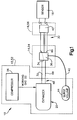
- Fig. 1 is a schematic diagram of a cryocooler in accordance with the present invention
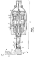
- Fig. 2 is a sectional view of details of a prior art Stirling expander and pulse tube expander
- Fig. 3 is a sectional view of details of a prior art pulse tube expander
- Fig. 4 is another sectional view of the pulse tube expander of Fig. 3;
- Fig. 5 is a schematic diagram of an alternate embodiment cryocooler in accordance with the invention.
- Fig. 6 is a cross-sectional view of one specific embodiment of a Stirling expander for the cryocooler of Fig. 5;
- Fig. 7 is a sectional view of another specific embodiment of a Stirling expander for use in the cryocooler of Fig. 5;
- Fig. 8 is a schematic diagram of yet another embodiment of a cryocooler in accordance with the present invention.
- Fig. 9 is a schematic diagram of still another embodiment of a cryocooler in accordance with the present invention.
- a two-stage cryocooler includes an ambient temperature portion, a first-stage temperature portion, and a second-stage temperature portion.
- the ambient temperature portion includes a surge volume that is gaseously coupled to a second-stage outlet, and thus in thermal communication with the first-stage temperature portion.
- the surge volume may be coupled to the second-stage outlet by use of an inertance tube. Locating the surge volume in the ambient temperature portion may advantageously reduce the size and mass of the first-stage temperature portion. Also, thermal losses may be reduced by maintaining the surge volume at ambient temperature. Space and structural requirements for maintaining the system may be met more easily with the surge volume maintained in the ambient temperature portion of the two-stage cooler.
- the surge volume may be a separate unit, or may be a plenum or other chamber within an expander in the ambient temperature portion.
- Fig. 1 schematically illustrates a two-stage cryocooler. Certain aspects of the cryocooler 10 may be similar to corresponding aspects described in U.S. Patent Nos. 6,167,707 and 6,330,800, the descriptions of which are incorporated herein by reference.
- the cryocooler 10 includes an ambient temperature portion 12, a first-stage temperature portion 14, and a second-stage temperature portion 16. The second-stage temperature portion is coupled to a component to be cooled, such as a sensor 18.
- the first-stage of the cryocooler 10 includes a Stirling expander 20 for providing cooling by expanding a working gas 22 compressed by a compressor 26.
- the second stage of the cryocooler 10 is a pulse tube expander 30.
- the compressor 26 supplies the compressed working gas 22 such as helium, to the first-stage Stirling expander 20.
- the working gas is expanded into an expansion volume 32.
- the working gas flows from the expansion volume 32 through a Stirling expander outlet 34, through a first-stage interface 36, and into the second-stage pulse tube expander 30.
- a second-stage thermal interface 40 is provided between the second-stage pulse tube expander 30 and a heat load in the form of the component to be cooled, such as the sensor 18.
- An inertance tube 42 is coupled on one end to the first-stage interface 36, and on another, opposite end to a surge volume 44 that is a part of the ambient temperature portion 12.
- the first-stage interface 36 is in gaseous communication with a second-stage outlet 46.
- the inertance tube 42 and the surge volume 44 provide modulation and control in the operation of the cryocooler 10.
- the inertance tube 42 and the surge volume 44 combine to reduce a phase shift in the operation of the cryocooler 10, to reduce the phase angle between a pressure wave and the cold end flow rate in the pulse tube expander 30.
- the characteristics of the inertance tube 42 such as the diameter and length of the inertance tube 42, may be selected so as to achieve a desired performance within the cryocooler.
- the desired performance may include a goal of minimizing the phase angle between the mass flow rate and the pressure wave at the cold end of the pulse tube 30, with an ultimate objective of optimizing thermodynamic efficiency.
- the ambient temperature portion 12 includes a warm end 48 of the Stirling expander 20, as will as the compressor 26 and the surge volume 44.
- the components of the ambient temperature portion 12 may be coupled to an ambient temperature structure 52.
- the first-stage temperature portion 14 includes the first-stage interface 36, which may be coupled to a first-stage structure 54.
- the second-stage portion 16 includes the second-stage thermal interface 40, which may be coupled to a second-stage temperature structure 56.
- the first-stage interface 36 may be supported in a cantilevered structure by the thin-walled tube of the expansion volume 32.
- the Stirling expander 20 has a plenum 60 and a cold head that includes a thin-walled cold cylinder, an expander inlet 62 disposed at a warm end of a first-stage regenerator 68, a moveable piston or displacer 66 disposed within a cold cylinder 69, and a heat exchanger 70.
- the displacer 66 is suspended on fore and aft flexures 72.
- the displacer 66 is controlled and moved by using a motor 76 located at a fore end of the plenum 60.
- a flexure-suspended balancer 78 may be used to provide internal reaction against the inertia of the moving displacer 66.
- the second-stage pulse tube expander 30 includes a second-stage regenerator (regenerative heat exchanger) 80, and a pulse tube 82.
- the second-stage regenerator 80 and the pulse tube 82 are gaseously coupled at one end to the second-stage interface 40. Both the second-stage regenerator 80 and the pulse tube 82 are physically connected to the first-stage interface 36 at an opposite end, but are not in direct communication with each other.
- the first-stage interface 36 has a port 86 that is connected to the second-stage outlet 46. One end of the inertance tube 42 is coupled to the port 86.
- a gas for instance helium flows into the expander inlet 62, and into the first-stage regenerator 68 and the heat exchanger 70.
- Gas flowing into the cold volume within the expander 20 is regenerated by the first-stage regenerator 68.
- a portion of the gas remains in the first-stage expansion volume of the first-stage regenerator 68.
- Progressively smaller portions of the gas continue to the second-stage regenerator 80, the pulse tube 82, and the inertance tube 42 in the surge volume 44.
- inertance tube 42 allows the advantage of moving the surge volume 44 to the ambient temperature portion 12 of the cryocooler 10, while simultaneously providing the required fluidic resistance and inductance to achieve the desired phase shift.
- surge volumes in Stirling/pulse tube hybrid cryocoolers have been maintained at a cold temperature, and have been mounted more or less directly on structure of a cold stage. Since the cold stages of a cryocooler may be suspended in an essentially cantilevered configuration, with the expander 20 supported, and other components of the cryocooler having to support their own weight in a cantilevered configuration, it is highly advantageous to shift the surge volume to the ambient portion of the cryocooler, where it is much more easily supported.
- the cantilevered structure of the cryocooler 10 may involve use of a fairly long, thin-walled tube (e.g., the cold cylinder 69) as a support. It will be appreciated that the greater amount of mass on the cantilevered structure, the greater the amount of stress that is put at the joint at the base of the thin-walled tube. Thus, by reducing the mass on the cantilevered structure, mechanical stresses in the cryocooler 10 may be reduced. Reducing the mass at the end of the cold cylinder 69 increases the natural frequency of the thin-walled tube that is the cold cylinder, which tends to make the dynamic response of the cryocooler 10 to loads such as vibrations from a space launch less severe. In addition, reducing the amount of size that must be maintained at the cryogenic first-stage temperature decreases the parasitic radiative load on the first stage, and thus increases the system cooling of objects or components to be cooled, that the cryocooler 10 may provide.
- a fairly long, thin-walled tube e.g., the
- moving the surge volume from the first-stage temperature portion to the ambient temperature portion may be advantageous from the point of view of packaging volume.
- moving the surge volume to the first-stage temperature portion reduces the cryogenic surface area, which may thereby reduce radiative parasitic losses.
- cryocooler 10 Another potential benefit of the cryocooler 10 is that entropy generated due to frictional loss in the inertance tube 42 may also be reduced. It will be appreciated that the inertance tube 42 is not maintained at a single temperature. One end of the inertance tube 42 is coupled to the first-stage interface 36, at the first-stage temperature. The opposite end of the inertance tube 42 is coupled to the surge volume 44, at an ambient temperature. Therefore, at least part of the inertance tube 42 is at a higher temperature than the first-stage temperature portion 14, due to the shifting of the surge volume 44 from the first-stage temperature portion 14 to the ambient temperature portion 12. Operation of the cryocooler 10 involves frictional losses within the inertance tube 42. These frictional losses generate entropy. Since the amount of entropy generated for a given amount of heating is inversely proportional to the temperature, it will be appreciated that raising the operating temperature of at least a portion of the inertance tube 42 reduces the amount of entropy created.
- heat generated due to friction within the inertance tube 42 has multiple thermal paths through which it may be removed.
- One thermal path is at the first-stage temperature, by coupling to the first-stage interface 36.
- Another thermal path is to the ambient surroundings.
- Providing multiple thermal paths, including a path to remove friction-generated heat at ambient temperature, may also be advantageous in terms of efficiently using the cooling generated by the cryocooler 10.
- Fig. 5 shows an alternate embodiment of the cryocooler 10.
- the surge volume 44 is placed at least partially within the Stirling expander 20.
- the plenum 60 (Fig. 2) may itself be utilized as the surge volume 44, as illustrated in Fig. 6.
- the surge volume 44 may be an isolated structure, taking up part of the plenum 60, within a pressure containment housing 90 of the Stirling expander 20. This configuration is illustrated in Fig. 7.
- the surge volume 44 may placed at least partially within the compressor 26.
- the placement of the surge volume 44 within the compressor 26 or the expander 20 may facilitate meeting design and/or packaging requirements.
- Fig. 8 Another alternative for the cryocooler 10 is shown in Fig. 8. As shown therein, the inertance tube 42 (Fig. 1) is replaced by a phase shifter 94 and a connecting flow line 96.
- the phase shifter may be any of a variety of suitable devices, such as an orifice, a porous plug, or an active device, to provide the desired phase shift between the mass flow rate and the pressure wave at the cold end of the pulse tube 30.
- phase shifter 94 alters mass flow distribution to the surge volume 44. It will be appreciated that by varying the stroke and/or phase angle of the displacer 66 in the first-stage expander 20, and by means of the inertance tube 42 and/or the phase shifter 94 (in conjunction with the surge volume 44), performance may be optimized at any operating point, including on orbit and in an actual thermal environment of a space craft, for example.
- Fig. 9 shows another embodiment of the cryocooler 10.
- the inertance tube 42 thermally coupled to the cold cylinder 69, for example by being wrapped around the cold cylinder 69.
- This thermal coupling between the inertance tube 42 and the cold cylinder 69 may reduce heat transfer from the warm end of the inertance tube 42 to the cold end of the inertance tube 42, which may be caused by oscillatory movement of gas in the inertance tube 42.
- the thermal coupling between the inertance tube 42 and the cold cylinder 69 may be accomplished by any of a variety of ways.
- the heat sinking between the inertance tube 42 and the may be accomplished by coupling them together at one point, at several distinct points, are essentially continuously along at least part of the length of the inertance tube 42 (as with the embodiment shown in Fig. 9).
Landscapes
- Engineering & Computer Science (AREA)
- Physics & Mathematics (AREA)
- Mechanical Engineering (AREA)
- Thermal Sciences (AREA)
- General Engineering & Computer Science (AREA)
- Compressors, Vaccum Pumps And Other Relevant Systems (AREA)
Abstract
Description
Claims (10)
- A hybrid multistage cryocooler (10) comprising:wherein the surge volume is maintained at an ambient temperature.a first-stage expander (20) having a first-stage expander outlet (34);a first-stage thermal interface (36);a second-stage expander (30) in communication with the first-stage expander outlet, via the first-stage thermal interface; anda surge volume (44) in communication with a second-stage expander outlet (46) of the second-stage expander, via the first-stage thermal interface;
- The cryocooler of claim 1, further comprising an inertance tube (42) coupling the surge volume to the first-stage thermal interface.
- The cryocooler of claim 2, wherein a first end of the inertance tube is at the ambient temperature, and wherein a second end of the inertance tube is a first-stage temperature that is lower than the ambient temperature.
- The cryocooler of claim 2 or claim 3, wherein the inertance tube is thermally coupled to a cold cylinder (69) surrounding an expansion volume that is in gaseous communication with the first-stage expander outlet.
- The cryocooler of any of claims 1 to 4, wherein the first-stage expander is a Stirling expander that includes:a cold cylinder (69) surrounding an expansion volume (32) that is in gaseous communication with the first-stage expander outlet;a displacer (66) which forces a working gas (22) through the expansion volume and a first-stage regenerator (68); anda motor (76) that drives the displacer.
- The cryocooler of any of claims 1 to 5, wherein the second-stage expander is pulse tube expander that includes:a pulse tube inlet;a pulse tube gas volume in gaseous communication with the pulse tube inlet, the gas volume including a second-stage regenerator (80) and a pulse tube gas column; anda second-stage heat exchanger (70) in thermal communication with the second-stage regenerator and the pulse tube gas column.
- The cryocooler of any of claims 1 to 6,
wherein the first-stage thermal interface is maintained at a first-stage cold temperature that is lower than the ambient temperature; and
wherein the first-stage thermal interface is cantilevered off an expansion volume (32) of the first-stage expander. - The cryocooler of any of claims 1 to 7, wherein the surge volume is within the Stirling expander.
- The cryocooler of any of claims 1 to 8, wherein the surge volume is inside at least part of a plenum (60) of the Stirling expander.
- The cryocooler of any of claims 1 to 9,
further comprising an ambient-stage structure (52);
wherein the surge volume and at least the first-stage expander are mechanically coupled to the ambient-stage structure.
Applications Claiming Priority (2)
| Application Number | Priority Date | Filing Date | Title |
|---|---|---|---|
| US10/762,867 US7062922B1 (en) | 2004-01-22 | 2004-01-22 | Cryocooler with ambient temperature surge volume |
| US762867 | 2004-01-22 |
Publications (3)
| Publication Number | Publication Date |
|---|---|
| EP1557621A2 true EP1557621A2 (en) | 2005-07-27 |
| EP1557621A3 EP1557621A3 (en) | 2006-05-31 |
| EP1557621B1 EP1557621B1 (en) | 2008-11-12 |
Family
ID=34634601
Family Applications (1)
| Application Number | Title | Priority Date | Filing Date |
|---|---|---|---|
| EP05250246A Ceased EP1557621B1 (en) | 2004-01-22 | 2005-01-19 | Cryocooler with ambient temperature surge volume |
Country Status (3)
| Country | Link |
|---|---|
| US (1) | US7062922B1 (en) |
| EP (1) | EP1557621B1 (en) |
| DE (1) | DE602005010918D1 (en) |
Cited By (1)
| Publication number | Priority date | Publication date | Assignee | Title |
|---|---|---|---|---|
| WO2008082433A1 (en) * | 2006-05-11 | 2008-07-10 | Raytheon Company | Hybrid cryocooler with multiple passive stages |
Families Citing this family (7)
| Publication number | Priority date | Publication date | Assignee | Title |
|---|---|---|---|---|
| US8783045B2 (en) * | 2005-01-13 | 2014-07-22 | Sumitomo Heavy Industries, Ltd. | Reduced input power cryogenic refrigerator |
| US8269893B2 (en) * | 2008-05-12 | 2012-09-18 | Flir Systems, Inc. | Optical payload electrical system |
| US10088203B2 (en) * | 2009-06-12 | 2018-10-02 | Raytheon Company | High efficiency compact linear cryocooler |
| US8639388B2 (en) | 2010-05-25 | 2014-01-28 | Raytheon Company | Time domain vibration reduction and control |
| US8491281B2 (en) | 2010-07-02 | 2013-07-23 | Raytheon Company | Long life seal and alignment system for small cryocoolers |
| US9551513B2 (en) * | 2014-06-12 | 2017-01-24 | Raytheon Company | Frequency-matched cryocooler scaling for low-cost, minimal disturbance space cooling |
| US10422329B2 (en) | 2017-08-14 | 2019-09-24 | Raytheon Company | Push-pull compressor having ultra-high efficiency for cryocoolers or other systems |
Family Cites Families (13)
| Publication number | Priority date | Publication date | Assignee | Title |
|---|---|---|---|---|
| JP3625511B2 (en) | 1995-02-23 | 2005-03-02 | 株式会社鈴木商館 | Gas cycle refrigerator |
| US5711157A (en) | 1995-05-16 | 1998-01-27 | Kabushiki Kaisha Toshiba | Cooling system having a plurality of cooling stages in which refrigerant-filled chamber type refrigerators are used |
| US5647219A (en) * | 1996-06-24 | 1997-07-15 | Hughes Electronics | Cooling system using a pulse-tube expander |
| US6330800B1 (en) | 1999-04-16 | 2001-12-18 | Raytheon Company | Apparatus and method for achieving temperature stability in a two-stage cryocooler |
| US6167707B1 (en) * | 1999-04-16 | 2001-01-02 | Raytheon Company | Single-fluid stirling/pulse tube hybrid expander |
| US6205812B1 (en) * | 1999-12-03 | 2001-03-27 | Praxair Technology, Inc. | Cryogenic ultra cold hybrid liquefier |
| US6256998B1 (en) * | 2000-04-24 | 2001-07-10 | Igcapd Cryogenics, Inc. | Hybrid-two-stage pulse tube refrigerator |
| US6378312B1 (en) * | 2000-05-25 | 2002-04-30 | Cryomech Inc. | Pulse-tube cryorefrigeration apparatus using an integrated buffer volume |
| US6374617B1 (en) * | 2001-01-19 | 2002-04-23 | Praxair Technology, Inc. | Cryogenic pulse tube system |
| JPWO2003001127A1 (en) * | 2001-06-21 | 2004-10-14 | エア・ウォーター株式会社 | Cool storage refrigerator |
| US20040000149A1 (en) * | 2002-07-01 | 2004-01-01 | Kirkconnell Carl S. | High-frequency, low-temperature regenerative heat exchanger |
| US6666033B1 (en) * | 2002-06-06 | 2003-12-23 | The Regents Of The University Of California | Method and apparatus for fine tuning an orifice pulse tube refrigerator |
| GB2415767B (en) * | 2003-01-17 | 2006-02-15 | Siemens Magnet Technology Ltd | Pulse tube refrigerator with a warm end heat exchanger having a secondary cooling mechanism comprising fins cooled by airflow |
-
2004
- 2004-01-22 US US10/762,867 patent/US7062922B1/en not_active Expired - Lifetime
-
2005
- 2005-01-19 DE DE602005010918T patent/DE602005010918D1/en not_active Expired - Lifetime
- 2005-01-19 EP EP05250246A patent/EP1557621B1/en not_active Ceased
Cited By (1)
| Publication number | Priority date | Publication date | Assignee | Title |
|---|---|---|---|---|
| WO2008082433A1 (en) * | 2006-05-11 | 2008-07-10 | Raytheon Company | Hybrid cryocooler with multiple passive stages |
Also Published As
| Publication number | Publication date |
|---|---|
| EP1557621B1 (en) | 2008-11-12 |
| EP1557621A3 (en) | 2006-05-31 |
| DE602005010918D1 (en) | 2008-12-24 |
| US7062922B1 (en) | 2006-06-20 |
Similar Documents
| Publication | Publication Date | Title |
|---|---|---|
| Radebaugh | Pulse tube cryocoolers for cooling infrared sensors | |
| US20110000228A1 (en) | Hybrid cryocooler with multiple passive stages | |
| EP1158256B1 (en) | Pulse-tube cryorefrigeration apparatus using an integrated buffer volume | |
| US5317878A (en) | Cryogenic cooling apparatus | |
| US6330800B1 (en) | Apparatus and method for achieving temperature stability in a two-stage cryocooler | |
| US6167707B1 (en) | Single-fluid stirling/pulse tube hybrid expander | |
| JP6403807B2 (en) | Frequency-matched cryocooler scaling for low-cost, minimum-disturbance space cooling | |
| CN100371657C (en) | Pulse tube refrigerator | |
| US7363767B2 (en) | Multi-stage pulse tube cryocooler | |
| US7062922B1 (en) | Cryocooler with ambient temperature surge volume | |
| US20090084114A1 (en) | Gas phase shifting inertance gap pulse tube cryocooler | |
| CN100432572C (en) | Cryogenic chiller system with frequency modulating mechanical resonator and method of operating same | |
| JP2003194428A (en) | Cooling device | |
| JP2001272126A (en) | Pulse tube refrigerator and superconducting magnet device using pulse tube refrigerator | |
| US7296418B2 (en) | Multi-stage cryocooler with concentric second stage | |
| EP1503154A1 (en) | Stirling/pulse tube hybrid cryocooler with gas flow shunt | |
| US8490414B2 (en) | Cryocooler with moving piston and moving cylinder | |
| Kirkconnell et al. | A Novel Multi-Stage Expander Concept | |
| Hu | Thermoacoustic expansion valve: A new type of expander to enhance performance of recuperative cryocooler systems | |
| US7165406B2 (en) | Integral pulse tube refrigerator and cryopump | |
| JP3363697B2 (en) | Refrigeration equipment | |
| JP2698477B2 (en) | Cryogenic refrigerator | |
| JP2004347175A (en) | Pulse tube refrigerator | |
| Walker et al. | Cryocoolers for the new high-temperature superconductors | |
| Liang et al. | Performances of Two Types of Miniature Multi-Bypass Coaxial Pulse Tube Refrigerators |
Legal Events
| Date | Code | Title | Description |
|---|---|---|---|
| PUAI | Public reference made under article 153(3) epc to a published international application that has entered the european phase |
Free format text: ORIGINAL CODE: 0009012 |
|
| AK | Designated contracting states |
Kind code of ref document: A2 Designated state(s): AT BE BG CH CY CZ DE DK EE ES FI FR GB GR HU IE IS IT LI LT LU MC NL PL PT RO SE SI SK TR |
|
| AX | Request for extension of the european patent |
Extension state: AL BA HR LV MK YU |
|
| PUAL | Search report despatched |
Free format text: ORIGINAL CODE: 0009013 |
|
| AK | Designated contracting states |
Kind code of ref document: A3 Designated state(s): AT BE BG CH CY CZ DE DK EE ES FI FR GB GR HU IE IS IT LI LT LU MC NL PL PT RO SE SI SK TR |
|
| AX | Request for extension of the european patent |
Extension state: AL BA HR LV MK YU |
|
| 17P | Request for examination filed |
Effective date: 20061110 |
|
| AKX | Designation fees paid |
Designated state(s): DE FR GB |
|
| 17Q | First examination report despatched |
Effective date: 20071128 |
|
| GRAP | Despatch of communication of intention to grant a patent |
Free format text: ORIGINAL CODE: EPIDOSNIGR1 |
|
| GRAS | Grant fee paid |
Free format text: ORIGINAL CODE: EPIDOSNIGR3 |
|
| GRAA | (expected) grant |
Free format text: ORIGINAL CODE: 0009210 |
|
| AK | Designated contracting states |
Kind code of ref document: B1 Designated state(s): DE FR GB |
|
| REG | Reference to a national code |
Ref country code: GB Ref legal event code: FG4D |
|
| REF | Corresponds to: |
Ref document number: 602005010918 Country of ref document: DE Date of ref document: 20081224 Kind code of ref document: P |
|
| PLBE | No opposition filed within time limit |
Free format text: ORIGINAL CODE: 0009261 |
|
| STAA | Information on the status of an ep patent application or granted ep patent |
Free format text: STATUS: NO OPPOSITION FILED WITHIN TIME LIMIT |
|
| 26N | No opposition filed |
Effective date: 20090813 |
|
| REG | Reference to a national code |
Ref country code: FR Ref legal event code: PLFP Year of fee payment: 12 |
|
| REG | Reference to a national code |
Ref country code: FR Ref legal event code: PLFP Year of fee payment: 13 |
|
| REG | Reference to a national code |
Ref country code: FR Ref legal event code: PLFP Year of fee payment: 14 |
|
| PGFP | Annual fee paid to national office [announced via postgrant information from national office to epo] |
Ref country code: GB Payment date: 20190116 Year of fee payment: 15 Ref country code: DE Payment date: 20190108 Year of fee payment: 15 |
|
| PGFP | Annual fee paid to national office [announced via postgrant information from national office to epo] |
Ref country code: FR Payment date: 20191216 Year of fee payment: 16 |
|
| REG | Reference to a national code |
Ref country code: DE Ref legal event code: R119 Ref document number: 602005010918 Country of ref document: DE |
|
| GBPC | Gb: european patent ceased through non-payment of renewal fee |
Effective date: 20200119 |
|
| PG25 | Lapsed in a contracting state [announced via postgrant information from national office to epo] |
Ref country code: DE Free format text: LAPSE BECAUSE OF NON-PAYMENT OF DUE FEES Effective date: 20200801 Ref country code: GB Free format text: LAPSE BECAUSE OF NON-PAYMENT OF DUE FEES Effective date: 20200119 |
|
| PG25 | Lapsed in a contracting state [announced via postgrant information from national office to epo] |
Ref country code: FR Free format text: LAPSE BECAUSE OF NON-PAYMENT OF DUE FEES Effective date: 20210131 |