EP1557562A1 - Distributing system for a piston hydraulic engine - Google Patents
Distributing system for a piston hydraulic engine Download PDFInfo
- Publication number
- EP1557562A1 EP1557562A1 EP04468002A EP04468002A EP1557562A1 EP 1557562 A1 EP1557562 A1 EP 1557562A1 EP 04468002 A EP04468002 A EP 04468002A EP 04468002 A EP04468002 A EP 04468002A EP 1557562 A1 EP1557562 A1 EP 1557562A1
- Authority
- EP
- European Patent Office
- Prior art keywords
- distribution
- outline
- piston
- hydraulic engine
- piston block
- Prior art date
- Legal status (The legal status is an assumption and is not a legal conclusion. Google has not performed a legal analysis and makes no representation as to the accuracy of the status listed.)
- Granted
Links
Images

Classifications
-
- F—MECHANICAL ENGINEERING; LIGHTING; HEATING; WEAPONS; BLASTING
- F03—MACHINES OR ENGINES FOR LIQUIDS; WIND, SPRING, OR WEIGHT MOTORS; PRODUCING MECHANICAL POWER OR A REACTIVE PROPULSIVE THRUST, NOT OTHERWISE PROVIDED FOR
- F03C—POSITIVE-DISPLACEMENT ENGINES DRIVEN BY LIQUIDS
- F03C1/00—Reciprocating-piston liquid engines
- F03C1/02—Reciprocating-piston liquid engines with multiple-cylinders, characterised by the number or arrangement of cylinders
- F03C1/04—Reciprocating-piston liquid engines with multiple-cylinders, characterised by the number or arrangement of cylinders with cylinders in star or fan arrangement
- F03C1/0403—Details, component parts specially adapted of such engines
- F03C1/0435—Particularities relating to the distribution members
- F03C1/0444—Particularities relating to the distribution members to plate-like distribution members
Definitions
- the present invention refers to a distribution system for a piston hydraulic engine, in particularly for an engine with a rotating piston block, said engine comprising a distribution body with distribution channels, and a block with pistons and feeding channels arranged coaxially to the distribution body.
- a distributor with hydraulic engines is common for all pistons, therefore, the piston position must alternate with regard to the distributor, or vice versa.
- the circular distributor is placed coaxially with the engine axis where it rotates, whereas the piston block remains stationary.
- Such a solution is disclosed in DE 19 653 591 C1.
- the drawback of said solution is wear and tear of the mutually cooperating distributor surfaces, resulting in an increased gap and leakage between channels and from the distributor into the housing, which increases with the power of three of the gap width.
- said solution does not provide a hollow shaft design of a hydraulic engine.
- a hydraulic engine comprising a distributor is known from the publication of the patent application DE 44 05 123.
- the separation of the sliding surfaces is solved by means of different combinations of contact, sealing, and resilient elements by means of which the fluid pressure is also applied to the rear of the distributor.
- a constantly moving gap is achieved therewith, while the stationary gap increases due to wear, resulting in the seals preloading.
- each distribution plate is formed with distribution apertures, the radial position thereof is equal to the radial position of distribution channels in the distribution body and of feeding channels in the piston block, respectively.
- the distribution apertures coincide with said channels, where the outline of each distribution aperture, in at least one of the distribution plates, is selected to be a circle, square, rectangle or trapezium, preferably an annular segment.
- annular spacers are inserted in a pressure-tight manner into each mouth of the distribution channels being provided, equally radially spaced, in the distribution body and piston block, respectively, said annular spacers being covered and held by means of an annular distribution plate.
- the latter is associated in a pressure-tight manner with the distribution body and piston block, respectively, and projects in an axial direction, when installed, above the surface of the distribution body and the piston block, respectively.
- Each distribution plate is formed with distribution apertures, the radial position thereof is equal to the radial position of the annular spacers in the mouth of each distribution channels.
- the outline of each distribution aperture, at least in one of the distribution plates, is selected to be a circle, square, rectangle or trapezium, preferably an annular segment.
- one of the distribution plates preferably the distribution plate being associated with the distribution body, is made of a wear-resistant material.
- the pistons and the piston block therewith wears more than the distribution body. Therefore, it has been proven that when the piston block has sufficient wear and requires replacing, the less resistant distribution plate attached to the piston block is replaced simultaneously.
- the distribution plates and the annular spacers are connected in a pressure-tight manner both mutually as well as with the distribution body and the piston block, respectively. Connection can be completed by means of soldering, gluing or similar. Both the distribution plates as well as the annular spacers can be manufactured by means of punching, sintering, die casting or similar convenient method.
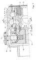
- a piston hydraulic engine consist of a two-part housing 1a, 1b joined face to face and a cam ring 2 arranged between the two halves of the housing 1a, 1b, where each contact surface between the housing and the cam ring 2 is appropriately sealed against leakage of hydraulic fluid.
- a cylindrical distribution body 3 is arranged in the first half of the housing 1a, said body 3 being in a manner known per se separated from the housing 1a by means of a plurality of sealing elements 4.
- Said housing 1a is formed on the inner surface thereof being in contact with the distribution body 3 with annular chambers 5, 6 intended for feeding and discharge, respectively, hydraulic fluid, said chambers being arranged between each pair of the sealing elements 4.
- the first chamber 5 is a high-pressure feeding chamber
- the second chamber 6 is a low-pressure discharge chamber. If it is required to change the direction of rotation, the pressure only needs to be switched in each of the chambers, so that the high-pressure chamber becomes the low-pressure chamber and vice versa.
- the distribution body 3 is secured against rotation relatively to the housing 1a in a manner known per se and therefore not shown in detail.
- the distribution body 3 is in its radial edge area and on the side facing the piston block formed with a plurality of distribution channels 7, 7' being equally spaced on the circumference of said body and extending parallel to the axis of the body 3, said channels being alternately connected to the high-pressure feeding chamber 5 and the low-pressure discharge chamber 6 provided in the housing 1a of the hydraulic engine. Said connection of the channels and annular chambers is carried out by means of transversal channels 8, 8'. The total number of said channels is always even and corresponds to double the cam lobes of the cam ring 2, said lobes cooperate with the pistons of the hydraulic engine.
- each distribution channel 7, 7' facing the piston block is closed with an annular spacer 9 comprising a through-hole 9', the outline thereof on the feeding side, i.e. the side facing each channel, is adapted to the outline of the channel 7, 7', while the outline of the through-hole 9' on the discharge side, i.e. the side averted from each channel, is selected in a manner that the coefficient of the fluid resistance is as low as possible.
- the outline of the through-hole 9' on the discharge side can be a circle, a square, a rectangle or a trapezium, preferably an annular segment, as it is shown in Fig. 2, Fig. 3 and Fig. 4.
- the annular spacers 9 are covered and held with an annular distribution plate 10 associated with the distribution body 3 and, when installed, projecting in an axial direction above the surface of the body 3.
- Said distribution plate 10 is formed with distribution apertures 11 the radial position thereof is equal to the radial position of the through-hole 9' of each annular spacer 9, where the outline of each distribution aperture 11 is identical to the outline of the through-hole 9' at the discharge side of each annular spacer 9, so that the through-holes 9' and the distribution apertures 11 entirely coincide.
- the distribution body 3 is formed on its opposite end with a plurality of radially spaced blind holes wherein compression springs 12 are arranged. The latter are loaded in the axial direction by means of a pressure plate 13 attached to the housing 1a.
- each piston 15 is continuously in contact with the cam ring 2 via a roller 16.
- the piston block 14 on the side facing the distribution body 3 is provided with a plurality of feeding channels 17 equally spaced on the circumference of said body and parallel to the axis of piston block 14, said channels being located at the same radial distance as are the channels 7, 7' in the distribution body 3.
- the number of the feeding channels 17 equals the number of the pistons 15 in the block 14.
- each channel 17 facing the distribution body 3 ends in an annular spacer 18 comprising a through-hole 18' the outline thereof at the discharging side, i.e. the side being averted from each channel, is adapted to the outline of the channel 17, while the outline of the through-hole 18' at the feeding side thereof, i.e. the side facing each channel, is selected in a manner that the coefficient of the fluid resistance is as low as possible.
- the outline of said through-hole on the feeding side can be a circle, a square, a rectangle or a trapezium, preferably an annular segment, as it is provided with the through-holes 9' in the annular spacers 9 in the distribution body 3.
- the annular spacers 18 are covered and held by means of a distribution plate 19 being associated with the piston block 14 and projecting, when installed, in an axial direction above the surface of the block 14.
- Said distribution plate 19 is formed with distribution apertures 20 the radial position thereof equaling the radial position of the through-hole 18' of each annular spacer 18, the outline of each distribution aperture 20 is identical to the outline of the through-hole 18' at the feeding side of each annular spacer 18, so that the through-holes 18' and the distribution apertures 20 entirely coincide.
- the above mentioned pressure plate 13 which presses a plurality of springs arranged in the distribution body 3 continuously provides load in the axial direction of the hydraulic engine resulting in the distribution plate 10 on the distribution body 3 being permanently pressed against the distribution plate 19 on the piston block 14, regardless of the wear and tear of the two distribution plates or the pressure of the hydraulic fluid.
- the distribution plates 10, 19 as well as the apertures 11, 20 could be produced by means of punching, sintering, or die casting, depending on the material used, since the present invention facilitates the use of arbitrary materials.
- Another embodiment of the distribution system is possible according to the present invention, where only distribution plates are employed, without annular spacers. Dimensions of the distribution apertures in each distribution plate can be optionally modified and the same applies to the channels. Such embodiment allows an increase in the allowable rotational frequency and decreasing of the hydraulic loss, respectively.
- the distribution plate which is less resistant against the wear and tear is installed on the piston block, thus it can be replaced quickly and simply, if necessary, together with the piston block.
Abstract
Description
- The present invention refers to a distribution system for a piston hydraulic engine, in particularly for an engine with a rotating piston block, said engine comprising a distribution body with distribution channels, and a block with pistons and feeding channels arranged coaxially to the distribution body.
- A distributor with hydraulic engines is common for all pistons, therefore, the piston position must alternate with regard to the distributor, or vice versa. The circular distributor is placed coaxially with the engine axis where it rotates, whereas the piston block remains stationary. Such a solution is disclosed in DE 19 653 591 C1. The drawback of said solution is wear and tear of the mutually cooperating distributor surfaces, resulting in an increased gap and leakage between channels and from the distributor into the housing, which increases with the power of three of the gap width. In addition, said solution does not provide a hollow shaft design of a hydraulic engine.
- A hydraulic engine comprising a distributor is known from the publication of the patent application DE 44 05 123. With said solution the separation of the sliding surfaces is solved by means of different combinations of contact, sealing, and resilient elements by means of which the fluid pressure is also applied to the rear of the distributor. A constantly moving gap is achieved therewith, while the stationary gap increases due to wear, resulting in the seals preloading.
- It is the object of the present invention to create a distribution system for a piston hydraulic engine that is easily maintained, and simultaneously the hydraulic engine will attain, with the minimal weight and size, relatively high pressures and revolutions with the same hydraulic losses of the distribution system.
- According to the invention the object as set above is solved by distribution plates being associated in a pressure-tight manner with the facing ends of a distribution body and a piston block, respectively, said distribution plates, when installed, project in an axial direction above the surface of the distribution body and the piston block, respectively. Each distribution plate is formed with distribution apertures, the radial position thereof is equal to the radial position of distribution channels in the distribution body and of feeding channels in the piston block, respectively. The distribution apertures coincide with said channels, where the outline of each distribution aperture, in at least one of the distribution plates, is selected to be a circle, square, rectangle or trapezium, preferably an annular segment.
- According to the present invention, such an embodiment of the distribution system is possible, that on the facing ends of the distribution body and the piston block, respectively, annular spacers are inserted in a pressure-tight manner into each mouth of the distribution channels being provided, equally radially spaced, in the distribution body and piston block, respectively, said annular spacers being covered and held by means of an annular distribution plate. The latter is associated in a pressure-tight manner with the distribution body and piston block, respectively, and projects in an axial direction, when installed, above the surface of the distribution body and the piston block, respectively. Each distribution plate is formed with distribution apertures, the radial position thereof is equal to the radial position of the annular spacers in the mouth of each distribution channels. The outline of each distribution aperture, at least in one of the distribution plates, is selected to be a circle, square, rectangle or trapezium, preferably an annular segment.
- It has been proven that if one of the distribution plates, preferably the distribution plate being associated with the distribution body, is made of a wear-resistant material. During operation of the hydraulic engine the pistons and the piston block therewith wears more than the distribution body. Therefore, it has been proven that when the piston block has sufficient wear and requires replacing, the less resistant distribution plate attached to the piston block is replaced simultaneously.
- The distribution plates and the annular spacers are connected in a pressure-tight manner both mutually as well as with the distribution body and the piston block, respectively. Connection can be completed by means of soldering, gluing or similar. Both the distribution plates as well as the annular spacers can be manufactured by means of punching, sintering, die casting or similar convenient method.
- Another embodiment of the distribution system is possible according to the present invention, where only distribution plates are employed, without annular spacers.
- The present invention will become more fully understood from the detailed description given hereinafter and the accompanying drawings, wherein
- Fig. 1
- shows a cross-section of a distributor of a hydraulic engine;
- Fig. 2
- shows the distributor viewed in the direction of the arrow II of Fig. 1;
- Fig. 3
- shows a cross-section along the line III-III of the distributor of Fig. 1; and
- Fig. 4
- shows piston block viewed in the direction of the arrow IV of Fig. 1.
- A piston hydraulic engine according to the invention consist of a two-
part housing cam ring 2 arranged between the two halves of thehousing cam ring 2 is appropriately sealed against leakage of hydraulic fluid. Acylindrical distribution body 3 is arranged in the first half of thehousing 1a, saidbody 3 being in a manner known per se separated from thehousing 1a by means of a plurality ofsealing elements 4. Saidhousing 1a is formed on the inner surface thereof being in contact with thedistribution body 3 withannular chambers 5, 6 intended for feeding and discharge, respectively, hydraulic fluid, said chambers being arranged between each pair of thesealing elements 4. In a given case, thefirst chamber 5 is a high-pressure feeding chamber, while the second chamber 6 is a low-pressure discharge chamber. If it is required to change the direction of rotation, the pressure only needs to be switched in each of the chambers, so that the high-pressure chamber becomes the low-pressure chamber and vice versa. Thedistribution body 3 is secured against rotation relatively to thehousing 1a in a manner known per se and therefore not shown in detail. - The
distribution body 3 is in its radial edge area and on the side facing the piston block formed with a plurality ofdistribution channels 7, 7' being equally spaced on the circumference of said body and extending parallel to the axis of thebody 3, said channels being alternately connected to the high-pressure feeding chamber 5 and the low-pressure discharge chamber 6 provided in thehousing 1a of the hydraulic engine. Said connection of the channels and annular chambers is carried out by means oftransversal channels 8, 8'. The total number of said channels is always even and corresponds to double the cam lobes of thecam ring 2, said lobes cooperate with the pistons of the hydraulic engine. The discharge portion of eachdistribution channel 7, 7' facing the piston block is closed with anannular spacer 9 comprising a through-hole 9', the outline thereof on the feeding side, i.e. the side facing each channel, is adapted to the outline of thechannel 7, 7', while the outline of the through-hole 9' on the discharge side, i.e. the side averted from each channel, is selected in a manner that the coefficient of the fluid resistance is as low as possible. The outline of the through-hole 9' on the discharge side can be a circle, a square, a rectangle or a trapezium, preferably an annular segment, as it is shown in Fig. 2, Fig. 3 and Fig. 4. Theannular spacers 9 are covered and held with anannular distribution plate 10 associated with thedistribution body 3 and, when installed, projecting in an axial direction above the surface of thebody 3. Saiddistribution plate 10 is formed withdistribution apertures 11 the radial position thereof is equal to the radial position of the through-hole 9' of eachannular spacer 9, where the outline of eachdistribution aperture 11 is identical to the outline of the through-hole 9' at the discharge side of eachannular spacer 9, so that the through-holes 9' and thedistribution apertures 11 entirely coincide. Thedistribution body 3 is formed on its opposite end with a plurality of radially spaced blind holes whereincompression springs 12 are arranged. The latter are loaded in the axial direction by means of apressure plate 13 attached to thehousing 1a. - Furthermore, inside said two-
part housing cam ring 2, there is apiston block 14 arranged coaxially with thedistribution body 3 in which is arranged a plurality ofpistons 15 being movable in a radial direction. Here, eachpiston 15 is continuously in contact with thecam ring 2 via aroller 16. Thepiston block 14 on the side facing thedistribution body 3 is provided with a plurality offeeding channels 17 equally spaced on the circumference of said body and parallel to the axis ofpiston block 14, said channels being located at the same radial distance as are thechannels 7, 7' in thedistribution body 3. The number of thefeeding channels 17 equals the number of thepistons 15 in theblock 14. The portion of eachchannel 17 facing thedistribution body 3 ends in anannular spacer 18 comprising a through-hole 18' the outline thereof at the discharging side, i.e. the side being averted from each channel, is adapted to the outline of thechannel 17, while the outline of the through-hole 18' at the feeding side thereof, i.e. the side facing each channel, is selected in a manner that the coefficient of the fluid resistance is as low as possible. The outline of said through-hole on the feeding side can be a circle, a square, a rectangle or a trapezium, preferably an annular segment, as it is provided with the through-holes 9' in theannular spacers 9 in thedistribution body 3. Theannular spacers 18 are covered and held by means of adistribution plate 19 being associated with thepiston block 14 and projecting, when installed, in an axial direction above the surface of theblock 14. Saiddistribution plate 19 is formed withdistribution apertures 20 the radial position thereof equaling the radial position of the through-hole 18' of eachannular spacer 18, the outline of eachdistribution aperture 20 is identical to the outline of the through-hole 18' at the feeding side of eachannular spacer 18, so that the through-holes 18' and thedistribution apertures 20 entirely coincide. - The above mentioned
pressure plate 13 which presses a plurality of springs arranged in thedistribution body 3 continuously provides load in the axial direction of the hydraulic engine resulting in thedistribution plate 10 on thedistribution body 3 being permanently pressed against thedistribution plate 19 on thepiston block 14, regardless of the wear and tear of the two distribution plates or the pressure of the hydraulic fluid. - According to the present invention, the
distribution plates apertures
Claims (11)
- A distribution system for a piston hydraulic engine, in particularly for an engine with a rotating piston block, said engine comprising distribution body with distribution channels, and a block with pistons and feeding channels arranged coaxially to the distribution body, characterised in that distribution plates (10; 19) are associated in a pressure-tight manner with the facing ends of a distribution body (3) and a piston block (14), respectively, said distribution plates, when installed, project in an axial direction above the surface of the distribution body (3) and the piston block (14), respectively, that the distribution plate (10) is formed with distribution apertures (11) and that the distribution plate (19) is formed with distribution apertures (20), the radial position of distribution apertures (11; 20) equals the radial position of distribution channels (7, 7') in the distribution body (3) and to the radial position of feeding channels (17) in the piston block (14), respectively, and that the distribution apertures (11; 20) coincide with the channels (7, 7'; 17), where the outline of each distribution aperture, in at least one of the distribution plates (10; 19), is selected to be a circle, square, rectangle or trapezium, preferably an annular segment.
- A distribution system for a piston hydraulic engine according to claim 1, characterised in that on the facing ends of the distribution body (3) and the piston block (14), respectively, annular spacers (9; 18) are inserted in a pressure-tight manner into each mouth of the distribution channels (7, 7'; 17) being provided, equally radially spaced, in the distribution body (3) and piston block (14), respectively, said annular spacers (9; 18) being covered and held by means of an annular distribution plate (10; 19) being associated in a pressure-tight manner with the distribution body (3) and piston block (14), respectively, and projects in axial direction, when installed, above the surface of the distribution body (3) and the piston block (14), respectively, where the distribution plate (10) is formed with distribution apertures (11) and the distribution plate (19) is formed with distribution apertures (20), respectively, the radial position of distribution apertures (11; 20) is equal to the radial position of the annular spacers (9; 18) in the mouth of distribution channels (7, 7'; 17), and that the outline of each distribution aperture, at least in one of the distribution plates (10; 19), is selected to be a circle, square, rectangle or trapezium, preferably an annular segment.
- A distribution system for a piston hydraulic engine according to claims 1 and 2, characterised in that one of the distribution plates (10; 19), preferably the distribution plate (10) being associated with the distribution body (3), is made of a material being more resistant against wear and tear.
- A distribution system for a piston hydraulic engine according to claims 1 and 2, characterised in that each annular spacer (9) associated with the distribution body (3) comprises a through-hole (9') the outline thereof at the feeding side is adapted to the outline of each distribution channel (7, 7') in the distribution body (3), and that each annular spacer (18) associated with the piston block (14) comprises a through-hole (18') the outline thereof at the discharge side is adapted to the outline of the feeding channel (17) in the piston block (14).
- A distribution system for a piston hydraulic engine according to any of claims 1 to 4, characterised in that the outline of the through-hole (9') in the annular spacer (9) at the discharge side and that the outline of the through-hole (18) in the annular spacer (18) at the feeding side are adapted to the outline of the apertures in each of the distribution plates (10, 19).
- A distribution system for a piston hydraulic engine according to any of claims 1 to 5, characterised in that the distribution plate (10) is formed with distribution apertures (11) the radial position thereof is equal to the radial position of the through-hole (9') of each annular spacer (9), where the outline of each through-hole (9') at the discharge side of each annular spacer (9) is identical to the outline of the distribution aperture (11), so that the through-holes (9') of the annular spacer (9) and of the distribution aperture (11) of the plate (10) entirely coincide.
- A distribution system for a piston hydraulic engine according to any of claims 1 to 6, characterised in that the distribution plate (19) is formed with distribution apertures (20) the radial position thereof is equal to the radial position of the through-hole (18') of each annular spacer (18), where the outline of each through-hole (18') at the feeding side of each annular spacer (18) is identical to the outline of the distribution aperture (20), so that the through-holes (18') of the annular spacer (18) and of the distribution aperture (20) of the plate (19) entirely coincide.
- A distribution system for a piston hydraulic engine according to any of claims 1 to 7, characterised in that the total number of said distribution channels (7, 7') in the distribution body (3) is always even and corresponds to double the cam lobes of the cam ring (2) which lobes cooperate with the pistons (15) of the hydraulic engine.
- A distribution system for a piston hydraulic engine according to any of claims 1 to 8, characterised in that the number of the feeding channels (17) in the piston block (14) is equal to the number of pistons (15) in the block (14).
- A distribution system for a piston hydraulic engine according to any of claims I to 9, characterised in that the distribution plates (10; 19) are connected in a pressure-tight manner to the distribution body (3) and the piston block (14), respectively, by means of gluing, soldering and similar.
- A distribution system for a piston hydraulic engine according to any of claims 1 to 10, characterised in that the the annular spacers (9; 18) are connected in a pressure-tight manner with the distribution body (3) and piston block (14), respectively, as well as with the distribution plate (10; 19), by means of gluing, soldering and similar.
Priority Applications (3)
| Application Number | Priority Date | Filing Date | Title |
|---|---|---|---|
| EP04468002A EP1557562B1 (en) | 2004-01-23 | 2004-01-23 | Distributing system for a piston hydraulic engine |
| DE602004021554T DE602004021554D1 (en) | 2004-01-23 | 2004-01-23 | Distributor device for a hydraulic radial piston motor |
| AT04468002T ATE434129T1 (en) | 2004-01-23 | 2004-01-23 | DISTRIBUTOR DEVICE FOR A HYDRAULIC RADIAL PISTON ENGINE |
Applications Claiming Priority (1)
| Application Number | Priority Date | Filing Date | Title |
|---|---|---|---|
| EP04468002A EP1557562B1 (en) | 2004-01-23 | 2004-01-23 | Distributing system for a piston hydraulic engine |
Publications (2)
| Publication Number | Publication Date |
|---|---|
| EP1557562A1 true EP1557562A1 (en) | 2005-07-27 |
| EP1557562B1 EP1557562B1 (en) | 2009-06-17 |
Family
ID=34626580
Family Applications (1)
| Application Number | Title | Priority Date | Filing Date |
|---|---|---|---|
| EP04468002A Expired - Lifetime EP1557562B1 (en) | 2004-01-23 | 2004-01-23 | Distributing system for a piston hydraulic engine |
Country Status (3)
| Country | Link |
|---|---|
| EP (1) | EP1557562B1 (en) |
| AT (1) | ATE434129T1 (en) |
| DE (1) | DE602004021554D1 (en) |
Citations (6)
| Publication number | Priority date | Publication date | Assignee | Title |
|---|---|---|---|---|
| FR1319986A (en) * | 1962-04-20 | 1963-03-01 | Angus George Co Ltd | Improvement in hydraulic pumps and motors |
| US3796136A (en) * | 1970-09-24 | 1974-03-12 | Kawasaki Heavy Ind Ltd | Fluid pump or fluid motor |
| US4522110A (en) * | 1982-09-08 | 1985-06-11 | Ab Hagglund & Soner | Hydraulic radial piston motor |
| DE4405123A1 (en) * | 1993-02-19 | 1994-08-25 | Poclain Hydraulics Sa | Pressure-fluid mechanism with sleeve-shaped contact pieces, such as, for example, a hydraulic motor or a hydraulic pump |
| DE19653591C1 (en) * | 1996-12-20 | 1998-01-15 | Korea Mach & Materials Inst | Fluid distributor for hydraulic, radial piston-type pump or motor |
| US6470786B2 (en) * | 1999-12-08 | 2002-10-29 | Santasalo Hydraulics Oy | Radial piston hydraulic engine |
-
2004
- 2004-01-23 EP EP04468002A patent/EP1557562B1/en not_active Expired - Lifetime
- 2004-01-23 DE DE602004021554T patent/DE602004021554D1/en not_active Expired - Lifetime
- 2004-01-23 AT AT04468002T patent/ATE434129T1/en not_active IP Right Cessation
Patent Citations (6)
| Publication number | Priority date | Publication date | Assignee | Title |
|---|---|---|---|---|
| FR1319986A (en) * | 1962-04-20 | 1963-03-01 | Angus George Co Ltd | Improvement in hydraulic pumps and motors |
| US3796136A (en) * | 1970-09-24 | 1974-03-12 | Kawasaki Heavy Ind Ltd | Fluid pump or fluid motor |
| US4522110A (en) * | 1982-09-08 | 1985-06-11 | Ab Hagglund & Soner | Hydraulic radial piston motor |
| DE4405123A1 (en) * | 1993-02-19 | 1994-08-25 | Poclain Hydraulics Sa | Pressure-fluid mechanism with sleeve-shaped contact pieces, such as, for example, a hydraulic motor or a hydraulic pump |
| DE19653591C1 (en) * | 1996-12-20 | 1998-01-15 | Korea Mach & Materials Inst | Fluid distributor for hydraulic, radial piston-type pump or motor |
| US6470786B2 (en) * | 1999-12-08 | 2002-10-29 | Santasalo Hydraulics Oy | Radial piston hydraulic engine |
Also Published As
| Publication number | Publication date |
|---|---|
| ATE434129T1 (en) | 2009-07-15 |
| EP1557562B1 (en) | 2009-06-17 |
| DE602004021554D1 (en) | 2009-07-30 |
Similar Documents
| Publication | Publication Date | Title |
|---|---|---|
| US5862704A (en) | Retainer mechanism for an axial piston machine | |
| US3961562A (en) | Multiple pump assembly | |
| US2313407A (en) | Power transmission | |
| US5697286A (en) | Fluid pressure unit with brake means | |
| EP2837824B1 (en) | Hydraulic machine, in particular hydraulic pressure exchanger | |
| US10107272B2 (en) | Sliding shoe for a hydrostatic axial piston machine | |
| KR960702888A (en) | Piston Pumps (Kolbenpumpe) | |
| US6398528B1 (en) | Dual lobe, split ring, variable roller vane pump | |
| EP1557562A1 (en) | Distributing system for a piston hydraulic engine | |
| US4095510A (en) | Radial piston pump | |
| WO2018215514A1 (en) | Hydrostatic relief and lubrication notches on valve segment running face | |
| US20070240563A1 (en) | DOUBLE-ACTING RADIAL PlSTON HYDRAULIC APPARATUS | |
| RU2301357C2 (en) | Rotary gate machine | |
| US3626981A (en) | Rotary slide valve | |
| WO1999024711A1 (en) | Radial piston hydraulic motor | |
| US20050252204A1 (en) | Hydraulic motor | |
| US4901830A (en) | Clutch and brake apparatus operable by compressible fluid, especially pneumatically | |
| US7661937B2 (en) | Axial piston machine and a control plate for an axial piston engine | |
| EP0387713B1 (en) | Gerotor type hydraulic motor or pump | |
| KR20140001148A (en) | Internal gear pump | |
| US3296977A (en) | Pressure loaded pump | |
| EP2133606B1 (en) | Cartridge and related methods | |
| EP0651159A1 (en) | Distribution unit for hydraulic radial piston motors | |
| EP3056727B1 (en) | Hydraulic machine | |
| CN111630305B (en) | Sealing element |
Legal Events
| Date | Code | Title | Description |
|---|---|---|---|
| PUAI | Public reference made under article 153(3) epc to a published international application that has entered the european phase |
Free format text: ORIGINAL CODE: 0009012 |
|
| 17P | Request for examination filed |
Effective date: 20040217 |
|
| AK | Designated contracting states |
Kind code of ref document: A1 Designated state(s): AT BE BG CH CY CZ DE DK EE ES FI FR GB GR HU IE IT LI LU MC NL PT RO SE SI SK TR |
|
| AX | Request for extension of the european patent |
Extension state: AL LT LV MK |
|
| AKX | Designation fees paid |
Designated state(s): AT BE BG CH CY CZ DE DK EE ES FI FR GB GR HU IE IT LI LU MC NL PT RO SE SI SK TR |
|
| GRAP | Despatch of communication of intention to grant a patent |
Free format text: ORIGINAL CODE: EPIDOSNIGR1 |
|
| 19U | Interruption of proceedings before grant |
Effective date: 20080117 |
|
| GRAS | Grant fee paid |
Free format text: ORIGINAL CODE: EPIDOSNIGR3 |
|
| 19W | Proceedings resumed before grant after interruption of proceedings |
Effective date: 20090504 |
|
| GRAA | (expected) grant |
Free format text: ORIGINAL CODE: 0009210 |
|
| RAP1 | Party data changed (applicant data changed or rights of an application transferred) |
Owner name: MANFREDA, MARIJA Owner name: PERAT, ERICA Owner name: MANFREDA, SIMON |
|
| RIN1 | Information on inventor provided before grant (corrected) |
Inventor name: MANFREDA, SIMON Inventor name: PERAT, ERICA Inventor name: MANFREDA, MARIJA |
|
| AK | Designated contracting states |
Kind code of ref document: B1 Designated state(s): AT BE BG CH CY CZ DE DK EE ES FI FR GB GR HU IE IT LI LU MC NL PT RO SE SI SK TR |
|
| REG | Reference to a national code |
Ref country code: GB Ref legal event code: FG4D |
|
| REG | Reference to a national code |
Ref country code: CH Ref legal event code: EP |
|
| REG | Reference to a national code |
Ref country code: IE Ref legal event code: FG4D |
|
| REF | Corresponds to: |
Ref document number: 602004021554 Country of ref document: DE Date of ref document: 20090730 Kind code of ref document: P |
|
| REG | Reference to a national code |
Ref country code: SE Ref legal event code: TRGR |
|
| PG25 | Lapsed in a contracting state [announced via postgrant information from national office to epo] |
Ref country code: FI Free format text: LAPSE BECAUSE OF FAILURE TO SUBMIT A TRANSLATION OF THE DESCRIPTION OR TO PAY THE FEE WITHIN THE PRESCRIBED TIME-LIMIT Effective date: 20090617 Ref country code: AT Free format text: LAPSE BECAUSE OF FAILURE TO SUBMIT A TRANSLATION OF THE DESCRIPTION OR TO PAY THE FEE WITHIN THE PRESCRIBED TIME-LIMIT Effective date: 20090617 |
|
| PG25 | Lapsed in a contracting state [announced via postgrant information from national office to epo] |
Ref country code: SI Free format text: LAPSE BECAUSE OF FAILURE TO SUBMIT A TRANSLATION OF THE DESCRIPTION OR TO PAY THE FEE WITHIN THE PRESCRIBED TIME-LIMIT Effective date: 20090617 |
|
| NLV1 | Nl: lapsed or annulled due to failure to fulfill the requirements of art. 29p and 29m of the patents act | ||
| RIN2 | Information on inventor provided after grant (corrected) |
Inventor name: MANFREDA, JURIJ |
|
| PG25 | Lapsed in a contracting state [announced via postgrant information from national office to epo] |
Ref country code: RO Free format text: LAPSE BECAUSE OF FAILURE TO SUBMIT A TRANSLATION OF THE DESCRIPTION OR TO PAY THE FEE WITHIN THE PRESCRIBED TIME-LIMIT Effective date: 20090617 Ref country code: ES Free format text: LAPSE BECAUSE OF FAILURE TO SUBMIT A TRANSLATION OF THE DESCRIPTION OR TO PAY THE FEE WITHIN THE PRESCRIBED TIME-LIMIT Effective date: 20090928 Ref country code: EE Free format text: LAPSE BECAUSE OF FAILURE TO SUBMIT A TRANSLATION OF THE DESCRIPTION OR TO PAY THE FEE WITHIN THE PRESCRIBED TIME-LIMIT Effective date: 20090617 |
|
| PG25 | Lapsed in a contracting state [announced via postgrant information from national office to epo] |
Ref country code: NL Free format text: LAPSE BECAUSE OF FAILURE TO SUBMIT A TRANSLATION OF THE DESCRIPTION OR TO PAY THE FEE WITHIN THE PRESCRIBED TIME-LIMIT Effective date: 20090617 Ref country code: SK Free format text: LAPSE BECAUSE OF FAILURE TO SUBMIT A TRANSLATION OF THE DESCRIPTION OR TO PAY THE FEE WITHIN THE PRESCRIBED TIME-LIMIT Effective date: 20090617 Ref country code: BE Free format text: LAPSE BECAUSE OF FAILURE TO SUBMIT A TRANSLATION OF THE DESCRIPTION OR TO PAY THE FEE WITHIN THE PRESCRIBED TIME-LIMIT Effective date: 20090617 |
|
| PG25 | Lapsed in a contracting state [announced via postgrant information from national office to epo] |
Ref country code: PT Free format text: LAPSE BECAUSE OF FAILURE TO SUBMIT A TRANSLATION OF THE DESCRIPTION OR TO PAY THE FEE WITHIN THE PRESCRIBED TIME-LIMIT Effective date: 20091017 Ref country code: BG Free format text: LAPSE BECAUSE OF FAILURE TO SUBMIT A TRANSLATION OF THE DESCRIPTION OR TO PAY THE FEE WITHIN THE PRESCRIBED TIME-LIMIT Effective date: 20090917 |
|
| PLBE | No opposition filed within time limit |
Free format text: ORIGINAL CODE: 0009261 |
|
| STAA | Information on the status of an ep patent application or granted ep patent |
Free format text: STATUS: NO OPPOSITION FILED WITHIN TIME LIMIT |
|
| PG25 | Lapsed in a contracting state [announced via postgrant information from national office to epo] |
Ref country code: DK Free format text: LAPSE BECAUSE OF FAILURE TO SUBMIT A TRANSLATION OF THE DESCRIPTION OR TO PAY THE FEE WITHIN THE PRESCRIBED TIME-LIMIT Effective date: 20090617 |
|
| 26N | No opposition filed |
Effective date: 20100318 |
|
| PG25 | Lapsed in a contracting state [announced via postgrant information from national office to epo] |
Ref country code: MC Free format text: LAPSE BECAUSE OF NON-PAYMENT OF DUE FEES Effective date: 20100131 |
|
| REG | Reference to a national code |
Ref country code: CH Ref legal event code: PL |
|
| GBPC | Gb: european patent ceased through non-payment of renewal fee |
Effective date: 20100123 |
|
| PG25 | Lapsed in a contracting state [announced via postgrant information from national office to epo] |
Ref country code: CH Free format text: LAPSE BECAUSE OF NON-PAYMENT OF DUE FEES Effective date: 20100131 Ref country code: LI Free format text: LAPSE BECAUSE OF NON-PAYMENT OF DUE FEES Effective date: 20100131 |
|
| PG25 | Lapsed in a contracting state [announced via postgrant information from national office to epo] |
Ref country code: GB Free format text: LAPSE BECAUSE OF NON-PAYMENT OF DUE FEES Effective date: 20100123 |
|
| PG25 | Lapsed in a contracting state [announced via postgrant information from national office to epo] |
Ref country code: IE Free format text: LAPSE BECAUSE OF NON-PAYMENT OF DUE FEES Effective date: 20100123 |
|
| PGFP | Annual fee paid to national office [announced via postgrant information from national office to epo] |
Ref country code: CZ Payment date: 20101215 Year of fee payment: 8 |
|
| PG25 | Lapsed in a contracting state [announced via postgrant information from national office to epo] |
Ref country code: IT Free format text: LAPSE BECAUSE OF NON-PAYMENT OF DUE FEES Effective date: 20100123 |
|
| PGRI | Patent reinstated in contracting state [announced from national office to epo] |
Ref country code: IT Effective date: 20110616 |
|
| PGFP | Annual fee paid to national office [announced via postgrant information from national office to epo] |
Ref country code: FR Payment date: 20120110 Year of fee payment: 9 |
|
| PGFP | Annual fee paid to national office [announced via postgrant information from national office to epo] |
Ref country code: DE Payment date: 20120130 Year of fee payment: 9 |
|
| PGFP | Annual fee paid to national office [announced via postgrant information from national office to epo] |
Ref country code: SE Payment date: 20120124 Year of fee payment: 9 Ref country code: IT Payment date: 20120124 Year of fee payment: 9 |
|
| PG25 | Lapsed in a contracting state [announced via postgrant information from national office to epo] |
Ref country code: CY Free format text: LAPSE BECAUSE OF FAILURE TO SUBMIT A TRANSLATION OF THE DESCRIPTION OR TO PAY THE FEE WITHIN THE PRESCRIBED TIME-LIMIT Effective date: 20090617 |
|
| PG25 | Lapsed in a contracting state [announced via postgrant information from national office to epo] |
Ref country code: HU Free format text: LAPSE BECAUSE OF FAILURE TO SUBMIT A TRANSLATION OF THE DESCRIPTION OR TO PAY THE FEE WITHIN THE PRESCRIBED TIME-LIMIT Effective date: 20091218 Ref country code: LU Free format text: LAPSE BECAUSE OF NON-PAYMENT OF DUE FEES Effective date: 20100123 |
|
| PG25 | Lapsed in a contracting state [announced via postgrant information from national office to epo] |
Ref country code: TR Free format text: LAPSE BECAUSE OF FAILURE TO SUBMIT A TRANSLATION OF THE DESCRIPTION OR TO PAY THE FEE WITHIN THE PRESCRIBED TIME-LIMIT Effective date: 20090617 |
|
| REG | Reference to a national code |
Ref country code: SE Ref legal event code: EUG |
|
| REG | Reference to a national code |
Ref country code: FR Ref legal event code: ST Effective date: 20130930 |
|
| PG25 | Lapsed in a contracting state [announced via postgrant information from national office to epo] |
Ref country code: SE Free format text: LAPSE BECAUSE OF NON-PAYMENT OF DUE FEES Effective date: 20130124 Ref country code: DE Free format text: LAPSE BECAUSE OF NON-PAYMENT OF DUE FEES Effective date: 20130801 Ref country code: CZ Free format text: LAPSE BECAUSE OF NON-PAYMENT OF DUE FEES Effective date: 20130123 |
|
| REG | Reference to a national code |
Ref country code: DE Ref legal event code: R119 Ref document number: 602004021554 Country of ref document: DE Effective date: 20130801 |
|
| PG25 | Lapsed in a contracting state [announced via postgrant information from national office to epo] |
Ref country code: FR Free format text: LAPSE BECAUSE OF NON-PAYMENT OF DUE FEES Effective date: 20130131 |
|
| PG25 | Lapsed in a contracting state [announced via postgrant information from national office to epo] |
Ref country code: IT Free format text: LAPSE BECAUSE OF NON-PAYMENT OF DUE FEES Effective date: 20130123 |
|
| PG25 | Lapsed in a contracting state [announced via postgrant information from national office to epo] |
Ref country code: GR Free format text: LAPSE BECAUSE OF FAILURE TO SUBMIT A TRANSLATION OF THE DESCRIPTION OR TO PAY THE FEE WITHIN THE PRESCRIBED TIME-LIMIT Effective date: 20090617 |