EP1557532A2 - Hohle Gebläseschaufel für Gasturbinentriebwerk, Gasturbinentriebwerk, sowie Herstellungsverfahren für eine solche hohle Gebläseschaufel - Google Patents
Hohle Gebläseschaufel für Gasturbinentriebwerk, Gasturbinentriebwerk, sowie Herstellungsverfahren für eine solche hohle Gebläseschaufel Download PDFInfo
- Publication number
- EP1557532A2 EP1557532A2 EP05250323A EP05250323A EP1557532A2 EP 1557532 A2 EP1557532 A2 EP 1557532A2 EP 05250323 A EP05250323 A EP 05250323A EP 05250323 A EP05250323 A EP 05250323A EP 1557532 A2 EP1557532 A2 EP 1557532A2
- Authority
- EP
- European Patent Office
- Prior art keywords
- ribs
- fan blade
- cavities
- hollow fan
- substrate
- Prior art date
- Legal status (The legal status is an assumption and is not a legal conclusion. Google has not performed a legal analysis and makes no representation as to the accuracy of the status listed.)
- Granted
Links
- 238000000034 method Methods 0.000 title claims description 11
- 239000000758 substrate Substances 0.000 claims description 21
- 238000003754 machining Methods 0.000 claims description 5
- 230000007704 transition Effects 0.000 abstract description 9
- 230000008859 change Effects 0.000 abstract description 3
- 239000007789 gas Substances 0.000 description 16
- 238000002485 combustion reaction Methods 0.000 description 6
- 239000000446 fuel Substances 0.000 description 4
- 230000000295 complement effect Effects 0.000 description 3
- RTAQQCXQSZGOHL-UHFFFAOYSA-N Titanium Chemical compound [Ti] RTAQQCXQSZGOHL-UHFFFAOYSA-N 0.000 description 2
- 230000001419 dependent effect Effects 0.000 description 2
- 239000000203 mixture Substances 0.000 description 2
- 230000008569 process Effects 0.000 description 2
- 229910052719 titanium Inorganic materials 0.000 description 2
- 239000010936 titanium Substances 0.000 description 2
- 238000005452 bending Methods 0.000 description 1
- 150000001875 compounds Chemical class 0.000 description 1
- 230000006835 compression Effects 0.000 description 1
- 238000007906 compression Methods 0.000 description 1
- 238000005520 cutting process Methods 0.000 description 1
- 230000003247 decreasing effect Effects 0.000 description 1
- 239000000284 extract Substances 0.000 description 1
- 238000004519 manufacturing process Methods 0.000 description 1
- 230000009467 reduction Effects 0.000 description 1
- 230000004044 response Effects 0.000 description 1
- 238000007665 sagging Methods 0.000 description 1
- 238000004513 sizing Methods 0.000 description 1
- 230000003068 static effect Effects 0.000 description 1
Images


Classifications
-
- F—MECHANICAL ENGINEERING; LIGHTING; HEATING; WEAPONS; BLASTING
- F01—MACHINES OR ENGINES IN GENERAL; ENGINE PLANTS IN GENERAL; STEAM ENGINES
- F01D—NON-POSITIVE DISPLACEMENT MACHINES OR ENGINES, e.g. STEAM TURBINES
- F01D5/00—Blades; Blade-carrying members; Heating, heat-insulating, cooling or antivibration means on the blades or the members
- F01D5/12—Blades
- F01D5/14—Form or construction
- F01D5/18—Hollow blades, i.e. blades with cooling or heating channels or cavities; Heating, heat-insulating or cooling means on blades
-
- B—PERFORMING OPERATIONS; TRANSPORTING
- B23—MACHINE TOOLS; METAL-WORKING NOT OTHERWISE PROVIDED FOR
- B23P—METAL-WORKING NOT OTHERWISE PROVIDED FOR; COMBINED OPERATIONS; UNIVERSAL MACHINE TOOLS
- B23P15/00—Making specific metal objects by operations not covered by a single other subclass or a group in this subclass
- B23P15/04—Making specific metal objects by operations not covered by a single other subclass or a group in this subclass turbine or like blades from several pieces
-
- F—MECHANICAL ENGINEERING; LIGHTING; HEATING; WEAPONS; BLASTING
- F01—MACHINES OR ENGINES IN GENERAL; ENGINE PLANTS IN GENERAL; STEAM ENGINES
- F01D—NON-POSITIVE DISPLACEMENT MACHINES OR ENGINES, e.g. STEAM TURBINES
- F01D5/00—Blades; Blade-carrying members; Heating, heat-insulating, cooling or antivibration means on the blades or the members
- F01D5/12—Blades
- F01D5/14—Form or construction
- F01D5/147—Construction, i.e. structural features, e.g. of weight-saving hollow blades
-
- F—MECHANICAL ENGINEERING; LIGHTING; HEATING; WEAPONS; BLASTING
- F04—POSITIVE - DISPLACEMENT MACHINES FOR LIQUIDS; PUMPS FOR LIQUIDS OR ELASTIC FLUIDS
- F04D—NON-POSITIVE-DISPLACEMENT PUMPS
- F04D29/00—Details, component parts, or accessories
- F04D29/26—Rotors specially for elastic fluids
- F04D29/32—Rotors specially for elastic fluids for axial flow pumps
- F04D29/321—Rotors specially for elastic fluids for axial flow pumps for axial flow compressors
- F04D29/324—Blades
-
- F—MECHANICAL ENGINEERING; LIGHTING; HEATING; WEAPONS; BLASTING
- F05—INDEXING SCHEMES RELATING TO ENGINES OR PUMPS IN VARIOUS SUBCLASSES OF CLASSES F01-F04
- F05D—INDEXING SCHEME FOR ASPECTS RELATING TO NON-POSITIVE-DISPLACEMENT MACHINES OR ENGINES, GAS-TURBINES OR JET-PROPULSION PLANTS
- F05D2220/00—Application
- F05D2220/30—Application in turbines
- F05D2220/32—Application in turbines in gas turbines
- F05D2220/324—Application in turbines in gas turbines to drive unshrouded, low solidity propeller
-
- F—MECHANICAL ENGINEERING; LIGHTING; HEATING; WEAPONS; BLASTING
- F05—INDEXING SCHEMES RELATING TO ENGINES OR PUMPS IN VARIOUS SUBCLASSES OF CLASSES F01-F04
- F05D—INDEXING SCHEME FOR ASPECTS RELATING TO NON-POSITIVE-DISPLACEMENT MACHINES OR ENGINES, GAS-TURBINES OR JET-PROPULSION PLANTS
- F05D2220/00—Application
- F05D2220/30—Application in turbines
- F05D2220/36—Application in turbines specially adapted for the fan of turbofan engines
-
- F—MECHANICAL ENGINEERING; LIGHTING; HEATING; WEAPONS; BLASTING
- F05—INDEXING SCHEMES RELATING TO ENGINES OR PUMPS IN VARIOUS SUBCLASSES OF CLASSES F01-F04
- F05D—INDEXING SCHEME FOR ASPECTS RELATING TO NON-POSITIVE-DISPLACEMENT MACHINES OR ENGINES, GAS-TURBINES OR JET-PROPULSION PLANTS
- F05D2230/00—Manufacture
- F05D2230/10—Manufacture by removing material
-
- F—MECHANICAL ENGINEERING; LIGHTING; HEATING; WEAPONS; BLASTING
- F05—INDEXING SCHEMES RELATING TO ENGINES OR PUMPS IN VARIOUS SUBCLASSES OF CLASSES F01-F04
- F05D—INDEXING SCHEME FOR ASPECTS RELATING TO NON-POSITIVE-DISPLACEMENT MACHINES OR ENGINES, GAS-TURBINES OR JET-PROPULSION PLANTS
- F05D2230/00—Manufacture
- F05D2230/60—Assembly methods
-
- Y—GENERAL TAGGING OF NEW TECHNOLOGICAL DEVELOPMENTS; GENERAL TAGGING OF CROSS-SECTIONAL TECHNOLOGIES SPANNING OVER SEVERAL SECTIONS OF THE IPC; TECHNICAL SUBJECTS COVERED BY FORMER USPC CROSS-REFERENCE ART COLLECTIONS [XRACs] AND DIGESTS
- Y02—TECHNOLOGIES OR APPLICATIONS FOR MITIGATION OR ADAPTATION AGAINST CLIMATE CHANGE
- Y02T—CLIMATE CHANGE MITIGATION TECHNOLOGIES RELATED TO TRANSPORTATION
- Y02T50/00—Aeronautics or air transport
- Y02T50/60—Efficient propulsion technologies, e.g. for aircraft
Definitions
- the present invention relates generally to gas turbine engines and more particularly to an improved hollow fan blade for a gas turbine engine.
- a gas turbine engine such as a turbo fan engine for an aircraft, includes a fan section, a compression section, a combustion section and a turbine section.
- An axis of the engine is centrally disposed within the engine and extends longitudinally through the sections.
- the primary flow path for working medium gases extends axially through the sections of the engine.
- a secondary flow path for working medium gases extends parallel to and radially outward of the primary flow path.
- the fan section includes a rotor assembly and a stator assembly.
- the rotor assembly of the fan includes a rotor disc and plurality of radially extending fan blades.
- the fan blades extend through the flow path and interact with the working medium gases and transfer energy between the fan blades and working medium gases.
- the stator assembly includes a fan case, which circumscribes the rotor assembly in close proximity to the tips of the fan blades.
- the fan draws the working medium gases, more particularly air, into the engine.
- the fan raises the pressure of the air drawn along the secondary flow path, thus producing useful thrust.
- the air drawn along the primary flow path into the compressor section is compressed.
- the compressed air is channeled to the combustion section where fuel is added to the compressed air and the air/fuel mixture is burned.
- the products of combustion are discharged to the turbine section.
- the turbine section extracts work from these products to power the fan and compressed air. Any energy from the products of combustion not needed to drive the fan and compressor contributes to useful thrust.
- each fan blade in some gas turbine engines are hollow.
- Each fan blade is made by combining two separate detail halves.
- Each half includes a plurality of cavities and ribs machined out to reduce the weight while forming a structurally sound internal configuration. These halves are subsequently bonded to form the hollow fan blade.
- the hollow fan blade is then subjected to forming operations at extremely high temperatures at which time it is given an airfoil shape and geometry. During the forming operation, the two detail halves are twisted and cambered under high temperatures to the desired shape.
- Inherent to the hollow fan blade design is a set of "skins" on the convex and concave side of the airfoil. These skins undergo significant compressive loading during the bonding and forming operations.
- the cavities are filled with high-pressure gas to maintain their geometry during the forming operation.
- the internal geometry of the hollow fan blades has been designed to provide bird-impact capabilities.
- the previous hollow fan blades had an internal geometry comprising numerous machined internal cavities and associated ribs primarily running radially with secondary ribs running chord -wise.
- the present invention provides a hollow fan blade with internal cavity and rib geometry with improved durability while minimizing weight and cost.
- the hollow fan blade has an internal geometry design that minimizes the number of internal cavities (or at least cutter plunge cuts), maximizes cutter size, and minimizes the time required to machine them.
- the improved internal cavity and rib pattern of the hollow fan blade improve structural, produceability and economic considerations. Ribs are oriented and biased to provide stiffness as needed (bird strike, tip rub, forming, etc.) with smooth transitions between regions.
- each cavity does not run solely radially or chordwise, but curve and change direction.
- the path of each cavity is curved sufficiently to eliminate any regions with long, straight cavities, which would have low inertia.
- cavities do not continue in any direction for lengths greater than half the blade chord (e.g. leading edge to trailing edge).
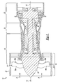
- a gas turbine engine 10 such as a turbofan gas turbine engine, circumferentially disposed about an engine centerline, or axial centerline axis 12 is shown.
- the engine 10 includes a fan 14, a compressor 16, a combustion section 18 and a turbine 20.
- air compressed in the compressor 16 is mixed with fuel which is burned in the combustion section 18 and expanded in turbine 20.
- the air compressed in the compressor and the fuel mixture expanded in the turbine 20 can both be referred to as a hot gas stream flow 28.
- the turbine 20 includes rotors 22 which rotate in response to the expansion, driving the compressor 16 and fan 14.
- the turbine 20 comprises alternating rows of rotary airfoils or blades 24 and static airfoils or vanes 26.
- the fan 14 is surrounded by a fan case 27 and includes a rotor assembly.
- the rotor assembly includes a rotor disk 29 and a plurality of fan blades 30.
- Each fan blade 30 extends radially outwardly from the rotor disk 29 across the working medium flow paths into proximity with the fan case 27.
- the fan blades 30 are hollow fan blades and include a first hollow fan blade detail half 30a and a second hollow fan blade detail half 30b.
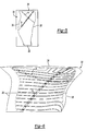
- a first embodiment of one fan blade detail half 30a is shown in Figure 2.
- the other fan blade detail half 30b would be complementary.
- the fan blade detail half 30a comprises a substrate 31, preferably Titanium, having a root edge 32 opposite a tip 34 and a leading edge 36 opposite a trailing edge 38.
- the fan blade detail half 30a includes Region A, which is approximately the radially inner-most third adjacent the root edge 32.
- Region B extends from Region A toward the tip 34, excluding a corner area adjacent the tip 34 and trailing edge 38, which is Region C.
- a plurality of elongated continuous cavities 40a-d are machined into the interior surface of the substrate 31.
- the cavities 40a-d are spaced from one another to form a plurality of continuous, non-intersecting ribs 42a-d.
- the ribs 42a-d are superplastically formed.
- the reference numeral 40 may be used to refer to the cavities 40 generically, while for specific subsets of cavities 40, the reference numeral 40 will be appended with one or more of the letters a-d.
- the reference numeral 42 may be used generically for the ribs 42a-d.
- the ribs 42 are oriented and biased in order to provide stiffness where needed, both during forming and during use in the turbine engine 10 of Figure 1. Further, the ribs 42 curve and change direction to eliminate any long, straight cavities 40, which would have low inertia. Preferably, the cavities 40 do not continue in any direction for lengths greater than half the blade chord.
- a first subset of cavities 40a and ribs 42a extend continuously from the root edge 32 toward the leading edge 36.
- the cavities 40a and ribs 42a extend from the root edge 32 initially radially outward (i.e. toward the tip 34) in Region A and then curve slightly away from and then toward the leading edge 36 at substantially a 45 degree angle but in a curved path in Region B.
- Region A is an area of significant blade pull (i.e. P/A).
- the portions of the ribs 42a in Region A help carry the load on the blade half 30a.
- the radially-extending portions of ribs 42a also minimize any stress concentration from the fillets.
- the slight curves in Region A prevent cavity 40a collapse during the forming process, when the fan blade detail half 30a is formed to its desired shape.
- a second subset of cavities 40b and ribs 42b extend continuously from the leading edge 36 toward the trailing edge 38 and curve downwardly slightly toward the root edge 32 at approximately a 45 degree angle, but in a curved path. These portions of the ribs 42a and ribs 42b in Region B extend substantially chordwise (at approximately a 45 degree angle) at the leading edge to provide bird strike stiffness.
- a third subset of cavities 40c and ribs 42c extend continuously along a curve approximately 45 degree chordwise path and then sharply curve perpendicularly to extend substantially radially toward the tip 34 and trailing edge 38 at approximately a 60 degree angle.
- a fourth subset of cavities 40d and ribs 42d extend continuously along a curved path substantially radially and toward the tip 34 and the trailing edge 38 at an approximately 60 degree angle.
- these ribs 42c and 42d are oriented transversely to the tip 34 to provide strength in the event of a tip 34 rub on the inner surface of the fan housing. Rib orientation in Region C is close to perpendicular to rib orientation of Region B where they meet in order to minimize mass of the fillets, which are a result of the cutter radius.
- stiffness is needed in the radial direction for tip rub events.
- Diagonal stiffness is needed in the corners adjacent the tip 34 and leading edge 36 and adjacent the tip 34 and trailing edge 38.
- the cavities 40 are all formed in the substrate 31 between the root edge 32 and the tip 34, and between the leading edge 36 and trailing edge 38.
- a frame 44 that is substantially equal to the thickness of the ribs 42.
- Each of the ribs 42 is contiguous with the frame 44 at both ends.
- Each of the cavities 40 begins and terminates adjacent the frame 44. The termination points occur in regions where the airfoil thickness is relatively low, which reduces the depth the cutters have to plunge into the part to start machining.
- FIG. 3 is a sectional view of the detail half 30a being machined by a cutter 54.
- Each cavity 40 has a floor 48 between opposite wall interior surfaces 50, some of which define the ribs 42.
- Each cavity 40 further includes a radius 42 transition between the wall interior surface 50 and the floor 48.
- the floor 48 and both wall interior surfaces 50 are preferably cut simultaneously in a single pass by the cutter 54. Because the cavities 40 are continuous and the ribs 42 do not intersect, each cavity 40 is formed in a single pass with a single cutter. Alternatively, the cavities 40 may each be formed in a single rough cut and a second, finish cut, but this is still a significant reduction in the number of cuts and cutters required.
- Figure 4 is a sectional view of a portion of the fan blade 30.
- the ribs 42 of fan blade detail half 30a are aligned and joined with the ribs 42 of the fan blade detail half 30b.
- the ribs 42 are tapered and transition into a compound radius (including radius 52 and the floor 48) that simulates the classical arch design element.
- the two radii (of the radius 52 and floor 48) should be selected such that the transition between each other and the tapered wall geometry are smooth and gradual.
- the sizing will depend upon the required load transitioning and carrying capabilities.
- the ratio of the width w of the cavity at the rib wall fillet run out to the thickness t of the floor 48 should be less than ten, but can be larger if the rib can be aligned more parallel to the load.
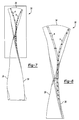
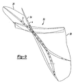
- the fan blade 30 is given an airfoil shape in a forming operation, which is illustrated in Figures 5-9.
- a forming operation the two detail halves are twisted and cambered to the desired shape under high heat. Because of the orientation and shape, as well as the spacing, of the ribs 42 as described and shown, the cavities 40 do not require a high pressure gas to increase their strength and prevent cavity collapse during the forming operation. This reduces the time and expense of the forming operation.
- Figure 5 is a rear view of the assembled fan blade 30 of Figure 4, illustrating two section lines, a and b, through the fan blade 30.
- Figure 6 is an enlarged, top perspective view of the fan blade of Figure 5.
- the section line a extends from a position generally near the corner of the tip 34 and leading edge 36 rearwardly to the trailing edge 38 and downwardly toward the root edge 32 ( Figure 5).
- the section lines a, b assist in visualizing the twisting and cambering of the fan blade 30 relative to the ribs 42 and cavities 40.
- Figure 7 is a front view of the fan blade of Figure 4 after the forming operation, showing the resulting locations of sections a and b.
- Figure 8 is an enlarged view of the upper portion of the fan blade of Figure 7.
- Figure 9 is top view of the fan blade of Figure 7.
- the orientation of the ribs 42 should be in a parallel plane with the load vector that results from forming loads during the pre-form and final form operations. This orientation presents the optimum configuration for load carrying capability and compressive stress transfer into the ribs 42 and away from the concave and convex skins.
- the specific orientation of the ribs 42 is therefore dependent upon the final shape of the fan blade 30, which will vary from one engine to another. Obviously, there are trade-offs and balancing among the various requirements as described herein, such that the ribs 42 cannot always be completely in a parallel plane with the load vector. For this reason ribs totally straight are avoided.
- FIG 10 illustrates a second embodiment of a fan blade detail half 60a that could be used in the turbine engine 10 of Figure 1. Again, the other fan blade detail half (not shown) would be complementary.
- the fan blade detail half 60a comprises a substrate 61, preferably Titanium, having a root edge 62 opposite a tip 64 and a leading edge 66 opposite a trailing edge 68.
- a plurality of elongated continuous cavities 70 are machined into or superplastically or otherwise formed on the interior surface of the substrate 61 in the manner described above with respect to Figures 3 and 4.
- the cavities 70 are spaced from one another to form a plurality of continuous non-intersecting ribs 72, 73. In this embodiment the spacing between ribs is held constant throughout.
- the cavities 70a-d extend continuously alongside ribs 72a-e and ribs 73.
- the cavities 70a-d also extend around freestanding ends 74 of some of the ribs 72a-e, thereby reducing the number of cavities 70a-d.
- the fan blade detail half 60a includes Region A, which is approximately the radially inward half.
- Region B comprises approximately a quarter adjacent the leading edge 66 and the tip 64.
- Region C comprises approximately a quarter adjacent the trailing edge 68 and the tip 64.
- a transition region is the central area substantially defined among the Regions A, B and C.
- a first subset of cavities 70a and ribs 72a extend continuously from the root edge 62 initially radially outward in Region A, and then curving toward the leading edge 36 at substantially a 45 degree angle but in a curved path in Region B.
- each cavity 70a extends continuously around a freestanding end 74 of one of the ribs 72a, thereby reducing the number of cavities 70a.
- Ribs 73 extend continuously parallel to the ribs 72a from the root edge 62 to the leading edge 66 between adjacent cavities 70a.
- a second subset of cavities 70b and ribs 72b extend continuously from the root edge 62 initially radially outward toward the tip 64 in Region A adjacent the trailing edge 68, and curving slightly toward the leading edge 66 in the transition region and then toward the trailing edge 68 at approximately a 45 degree angle in a slightly curved path in Region C.
- Each cavity 70b also extends continuously around a freestanding end 74 of one of the ribs 72b, thereby reducing the number of cavities 70b.
- Ribs 73 are defined between adjacent cavities 70b and are parallel to the ribs 72b.
- a third subset of ribs 72c extend from the leading edge 66 toward the trailing edge 68 and curve downwardly slightly toward the root edge 62 in a curved path in Region B.
- At least one cavity 70c extends continuously in a serpentine path around one free end 74 of one rib 72c, around the opposite free end 74 of the next rib 72c and again around the opposite free end 74 of the next rib 72c.
- the serpentine path further reduces the number of cavities 70 needed to define the ribs 72.
- a fourth set of ribs 72d are each at least partially defined by a single cavity 70d.
- the cavity 70d and a rib 72d extend continuously from the root edge 62 radially outward (toward the tip 64) in Region A, then curve slightly toward the leading edge 66 in the transition region, and then slightly toward the trailing edge 68 at an approximately 60 degree angle in Region C.
- the cavity 70d extends continuously around the free end 74 of the rib 72d and then around alternating free ends 74 of two more ribs 72d oriented approximately 60 degrees toward the tip 64.
- the cavity 70d then extends continuously into Region B around alternating free ends 74 of a plurality of ribs 72e oriented substantially parallel to the ribs 72c, i.e. substantially chordwise, approximately 30 degrees and curved slightly. This long serpentine path of cavity 70d further reduces the number of cavities 70 necessary to create ribs 72.
- Region A is an area of significant blade pull.
- the portions of the ribs 72a, b, d in Region A help carry the load on the blade half 60a.
- the radially-extending portions of ribs 72a, b, d also minimize any stress concentration from the fillets.
- the substantially chordwise orientation of the portions of ribs 72a, c, d in Region B provide bird strike strength.
- the substantially radial orientation of the portions of the ribs 72b, d in Region C provide strength to the tip in the event of tip rub on interior of the fan housing.
- Figure 11 shows an enlarged view of an alternate rib 72' for the detail half 60a of Figure 10.
- the alternate rib 72' would also be used in the complementary detail half (not shown).
- the alternate rib 72' has a freestanding end 74' that is flared such that it has a larger width than the rest of the rib 72'.
- the cavity 70 extends continuously around the free, flared end 74' of the rib 72'.
- the ribs 72' are tapered and have a radius 82 transition into the floor 78.
- the radius 82 extends around the flared end 74'.
- the ribs 73' between adjacent cavities 70 have a generally constant width.
- the flared end 74' increases the strength of the bond joint in that location. It also increases the footprint at the base of the fillet, which improves the stiffness in the vicinity of the flared end 74', which reduces the load on the bond joint.
- Figure 12 shows one possible arrangement of a plurality of the ribs 72' with the flared ends 74'. Incorporating the flared ends 74' is achievable with minimum weight impact if the cavity 70 ends can be staggered as shown in Figure 12.
- the ribs 72' and the cavities 70 that extend continuously around the flared ends 74' of the ribs 72' are staggered, such that the increased width of a flared end 74' of one rib 72'is not aligned with the flared ends 74' of the adjacent ribs 72' (referring to "alignment" in a direction perpendicular to the ribs 72').
- Oblique ribs 72' are a good way to stagger the ends 74'.
- the thickness changes needs to be gradual or they force curvature into successive neighbors as shown in Figure 13.
- the flared ends 74', ribs 72' and cavities 70 are not staggered, but are aligned.
- the increase in thickness at the flared ends 74' is taken from a decreased thickness in adjacent ribs 73" between adjacent cavities 70.
Applications Claiming Priority (2)
| Application Number | Priority Date | Filing Date | Title |
|---|---|---|---|
| US765741 | 2004-01-26 | ||
| US10/765,741 US7070391B2 (en) | 2004-01-26 | 2004-01-26 | Hollow fan blade for gas turbine engine |
Publications (3)
| Publication Number | Publication Date |
|---|---|
| EP1557532A2 true EP1557532A2 (de) | 2005-07-27 |
| EP1557532A3 EP1557532A3 (de) | 2006-01-18 |
| EP1557532B1 EP1557532B1 (de) | 2008-06-04 |
Family
ID=34634639
Family Applications (1)
| Application Number | Title | Priority Date | Filing Date |
|---|---|---|---|
| EP05250323A Active EP1557532B1 (de) | 2004-01-26 | 2005-01-24 | Hälfte einer hohlen Gebläseschaufel, hohle Gebläseschaufel für Gasturbinentriebwerk, sowie entsprechendes Herstellungsverfahren |
Country Status (5)
| Country | Link |
|---|---|
| US (1) | US7070391B2 (de) |
| EP (1) | EP1557532B1 (de) |
| JP (1) | JP4166223B2 (de) |
| AT (1) | ATE397513T1 (de) |
| DE (1) | DE602005007275D1 (de) |
Cited By (2)
| Publication number | Priority date | Publication date | Assignee | Title |
|---|---|---|---|---|
| US7794197B2 (en) | 2005-08-04 | 2010-09-14 | Rolls-Royce Plc | Aerofoil blades with improved impact resistance |
| EP2948636A4 (de) * | 2013-01-23 | 2016-11-23 | United Technologies Corp | Gasturbinenmotorkomponente mit konturiertem rippenende |
Families Citing this family (19)
| Publication number | Priority date | Publication date | Assignee | Title |
|---|---|---|---|---|
| US7334333B2 (en) * | 2004-01-26 | 2008-02-26 | United Technologies Corporation | Method for making a hollow fan blade with machined internal cavities |
| US7458780B2 (en) * | 2005-08-15 | 2008-12-02 | United Technologies Corporation | Hollow fan blade for gas turbine engine |
| US7993105B2 (en) * | 2005-12-06 | 2011-08-09 | United Technologies Corporation | Hollow fan blade for gas turbine engine |
| JP4863162B2 (ja) * | 2006-05-26 | 2012-01-25 | 株式会社Ihi | ターボファンエンジンのファン動翼 |
| US8257035B2 (en) * | 2007-12-05 | 2012-09-04 | Siemens Energy, Inc. | Turbine vane for a gas turbine engine |
| US8240999B2 (en) * | 2009-03-31 | 2012-08-14 | United Technologies Corporation | Internally supported airfoil and method for internally supporting a hollow airfoil during manufacturing |
| US20110211965A1 (en) * | 2010-02-26 | 2011-09-01 | United Technologies Corporation | Hollow fan blade |
| RU2494262C2 (ru) * | 2011-05-10 | 2013-09-27 | Открытое Акционерное общество "Научно-производственное предприятие "Мотор" | Колесо компрессора с облегченными лопатками |
| US8801367B2 (en) * | 2011-09-23 | 2014-08-12 | United Technologies Corporation | Hollow fan blade channel configuration to reduce stress |
| US8807925B2 (en) * | 2011-09-23 | 2014-08-19 | United Technologies Corporation | Fan blade having internal rib break-edge |
| US8807924B2 (en) * | 2011-09-23 | 2014-08-19 | United Technologies Corporation | Fan blade channel termination |
| US9810077B2 (en) | 2012-01-31 | 2017-11-07 | United Technologies Corporation | Fan blade attachment of gas turbine engine |
| ITCO20120059A1 (it) * | 2012-12-13 | 2014-06-14 | Nuovo Pignone Srl | Metodi per produrre pale cave sagomate in 3d di turbomacchine mediante produzione additiva, pale cave di turbomacchina e turbomacchine |
| US10156157B2 (en) * | 2015-02-13 | 2018-12-18 | United Technologies Corporation | S-shaped trip strips in internally cooled components |
| US9845728B2 (en) | 2015-10-15 | 2017-12-19 | Rohr, Inc. | Forming a nacelle inlet for a turbine engine propulsion system |
| GB201702383D0 (en) * | 2017-02-14 | 2017-03-29 | Rolls Royce Plc | Gas turbine engine fan blade with axial lean |
| US11433990B2 (en) | 2018-07-09 | 2022-09-06 | Rohr, Inc. | Active laminar flow control system with composite panel |
| US11174737B2 (en) | 2019-06-12 | 2021-11-16 | Raytheon Technologies Corporation | Airfoil with cover for gas turbine engine |
| US11225874B2 (en) | 2019-12-20 | 2022-01-18 | Raytheon Technologies Corporation | Turbine engine rotor blade with castellated tip surface |
Citations (2)
| Publication number | Priority date | Publication date | Assignee | Title |
|---|---|---|---|---|
| US3017159A (en) * | 1956-11-23 | 1962-01-16 | Curtiss Wright Corp | Hollow blade construction |
| EP0902165A2 (de) * | 1997-09-10 | 1999-03-17 | United Technologies Corporation | Schlagfeste hohle Schaufel |
Family Cites Families (10)
| Publication number | Priority date | Publication date | Assignee | Title |
|---|---|---|---|---|
| US2644665A (en) * | 1947-12-13 | 1953-07-07 | Chrysler Corp | Article with passages |
| US3628226A (en) * | 1970-03-16 | 1971-12-21 | Aerojet General Co | Method of making hollow compressor blades |
| US4514144A (en) * | 1983-06-20 | 1985-04-30 | General Electric Company | Angled turbulence promoter |
| US5063662A (en) * | 1990-03-22 | 1991-11-12 | United Technologies Corporation | Method of forming a hollow blade |
| US5516593A (en) * | 1994-04-29 | 1996-05-14 | United Technologies Corporation | Article with material absorption cavities to reduce buckling during diffusion bonding |
| US5820338A (en) | 1997-04-24 | 1998-10-13 | United Technologies Corporation | Fan blade interplatform seal |
| US5836744A (en) | 1997-04-24 | 1998-11-17 | United Technologies Corporation | Frangible fan blade |
| US6637186B1 (en) | 1997-11-11 | 2003-10-28 | United Technologies Corporation | Fan case liner |
| US6416099B1 (en) * | 2000-11-30 | 2002-07-09 | Abb Technology Ag | Lifting tool for automatic centering and 180 degree rotation |
| US6607355B2 (en) | 2001-10-09 | 2003-08-19 | United Technologies Corporation | Turbine airfoil with enhanced heat transfer |
-
2004
- 2004-01-26 US US10/765,741 patent/US7070391B2/en not_active Expired - Lifetime
-
2005
- 2005-01-24 AT AT05250323T patent/ATE397513T1/de not_active IP Right Cessation
- 2005-01-24 DE DE602005007275T patent/DE602005007275D1/de active Active
- 2005-01-24 EP EP05250323A patent/EP1557532B1/de active Active
- 2005-01-25 JP JP2005017034A patent/JP4166223B2/ja not_active Expired - Fee Related
Patent Citations (2)
| Publication number | Priority date | Publication date | Assignee | Title |
|---|---|---|---|---|
| US3017159A (en) * | 1956-11-23 | 1962-01-16 | Curtiss Wright Corp | Hollow blade construction |
| EP0902165A2 (de) * | 1997-09-10 | 1999-03-17 | United Technologies Corporation | Schlagfeste hohle Schaufel |
Cited By (2)
| Publication number | Priority date | Publication date | Assignee | Title |
|---|---|---|---|---|
| US7794197B2 (en) | 2005-08-04 | 2010-09-14 | Rolls-Royce Plc | Aerofoil blades with improved impact resistance |
| EP2948636A4 (de) * | 2013-01-23 | 2016-11-23 | United Technologies Corp | Gasturbinenmotorkomponente mit konturiertem rippenende |
Also Published As
| Publication number | Publication date |
|---|---|
| JP2005207425A (ja) | 2005-08-04 |
| US20050163617A1 (en) | 2005-07-28 |
| EP1557532B1 (de) | 2008-06-04 |
| ATE397513T1 (de) | 2008-06-15 |
| DE602005007275D1 (de) | 2008-07-17 |
| EP1557532A3 (de) | 2006-01-18 |
| JP4166223B2 (ja) | 2008-10-15 |
| US7070391B2 (en) | 2006-07-04 |
Similar Documents
| Publication | Publication Date | Title |
|---|---|---|
| EP1557528B1 (de) | Hälfte einer hohlen Gebläseschaufel, hohle Gebläseschaufel für Gasturbinentriebwerk, sowie entsprechendes Herstellungsverfahren | |
| EP1557532B1 (de) | Hälfte einer hohlen Gebläseschaufel, hohle Gebläseschaufel für Gasturbinentriebwerk, sowie entsprechendes Herstellungsverfahren | |
| EP1557530B1 (de) | Herstellungsverfahren für eine hohle Gebläseschaufel einer Strömungsmaschine | |
| EP1557531B1 (de) | Hälfte einer hohlen Gebläseschaufel, hohle Gebläseschaufel für Gasturbinentriebwerk, sowie entsprechendes Herstellungsverfahren | |
| EP1557529B1 (de) | Hohle Gebläseschaufel für Strömungsmaschine und entsprechendes Herstellungsverfahren | |
| US7993105B2 (en) | Hollow fan blade for gas turbine engine | |
| US7458780B2 (en) | Hollow fan blade for gas turbine engine | |
| US6471474B1 (en) | Method and apparatus for reducing rotor assembly circumferential rim stress | |
| JP5246840B2 (ja) | ロータブレードおよびロータ | |
| EP0924381B1 (de) | Schwingungsgedämpfte Turbomaschinenschaufel | |
| JP2008032000A (ja) | 動翼及びガスタービンエンジンアセンブリ |
Legal Events
| Date | Code | Title | Description |
|---|---|---|---|
| PUAI | Public reference made under article 153(3) epc to a published international application that has entered the european phase |
Free format text: ORIGINAL CODE: 0009012 |
|
| AK | Designated contracting states |
Kind code of ref document: A2 Designated state(s): AT BE BG CH CY CZ DE DK EE ES FI FR GB GR HU IE IS IT LI LT LU MC NL PL PT RO SE SI SK TR |
|
| AX | Request for extension of the european patent |
Extension state: AL BA HR LV MK YU |
|
| PUAL | Search report despatched |
Free format text: ORIGINAL CODE: 0009013 |
|
| AK | Designated contracting states |
Kind code of ref document: A3 Designated state(s): AT BE BG CH CY CZ DE DK EE ES FI FR GB GR HU IE IS IT LI LT LU MC NL PL PT RO SE SI SK TR |
|
| AX | Request for extension of the european patent |
Extension state: AL BA HR LV MK YU |
|
| RIC1 | Information provided on ipc code assigned before grant |
Ipc: B23P 15/04 20060101AFI20051125BHEP Ipc: F04D 29/38 20060101ALI20051125BHEP Ipc: F01D 5/18 20060101ALI20051125BHEP Ipc: F01D 5/14 20060101ALI20051125BHEP Ipc: F04D 29/32 20060101ALI20051125BHEP |
|
| 17P | Request for examination filed |
Effective date: 20060303 |
|
| AKX | Designation fees paid |
Designated state(s): AT BE BG CH CY CZ DE DK EE ES FI FR GB GR HU IE IS IT LI LT LU MC NL PL PT RO SE SI SK TR |
|
| GRAP | Despatch of communication of intention to grant a patent |
Free format text: ORIGINAL CODE: EPIDOSNIGR1 |
|
| RTI1 | Title (correction) |
Free format text: HOLLOW FAN BLADE DETAIL HALF, HOLLOW FAN BLADE FOR A GAS TURBINE ENGINE AND CORRESPONDING MANUFACTURING METHOD |
|
| GRAS | Grant fee paid |
Free format text: ORIGINAL CODE: EPIDOSNIGR3 |
|
| GRAA | (expected) grant |
Free format text: ORIGINAL CODE: 0009210 |
|
| AK | Designated contracting states |
Kind code of ref document: B1 Designated state(s): AT BE BG CH CY CZ DE DK EE ES FI FR GB GR HU IE IS IT LI LT LU MC NL PL PT RO SE SI SK TR |
|
| REG | Reference to a national code |
Ref country code: GB Ref legal event code: FG4D |
|
| REG | Reference to a national code |
Ref country code: CH Ref legal event code: EP |
|
| REF | Corresponds to: |
Ref document number: 602005007275 Country of ref document: DE Date of ref document: 20080717 Kind code of ref document: P |
|
| REG | Reference to a national code |
Ref country code: IE Ref legal event code: FG4D |
|
| PG25 | Lapsed in a contracting state [announced via postgrant information from national office to epo] |
Ref country code: SI Free format text: LAPSE BECAUSE OF FAILURE TO SUBMIT A TRANSLATION OF THE DESCRIPTION OR TO PAY THE FEE WITHIN THE PRESCRIBED TIME-LIMIT Effective date: 20080604 Ref country code: FI Free format text: LAPSE BECAUSE OF FAILURE TO SUBMIT A TRANSLATION OF THE DESCRIPTION OR TO PAY THE FEE WITHIN THE PRESCRIBED TIME-LIMIT Effective date: 20080604 Ref country code: ES Free format text: LAPSE BECAUSE OF FAILURE TO SUBMIT A TRANSLATION OF THE DESCRIPTION OR TO PAY THE FEE WITHIN THE PRESCRIBED TIME-LIMIT Effective date: 20080915 |
|
| PG25 | Lapsed in a contracting state [announced via postgrant information from national office to epo] |
Ref country code: AT Free format text: LAPSE BECAUSE OF FAILURE TO SUBMIT A TRANSLATION OF THE DESCRIPTION OR TO PAY THE FEE WITHIN THE PRESCRIBED TIME-LIMIT Effective date: 20080604 Ref country code: NL Free format text: LAPSE BECAUSE OF FAILURE TO SUBMIT A TRANSLATION OF THE DESCRIPTION OR TO PAY THE FEE WITHIN THE PRESCRIBED TIME-LIMIT Effective date: 20080604 Ref country code: PL Free format text: LAPSE BECAUSE OF FAILURE TO SUBMIT A TRANSLATION OF THE DESCRIPTION OR TO PAY THE FEE WITHIN THE PRESCRIBED TIME-LIMIT Effective date: 20080604 |
|
| NLV1 | Nl: lapsed or annulled due to failure to fulfill the requirements of art. 29p and 29m of the patents act | ||
| PG25 | Lapsed in a contracting state [announced via postgrant information from national office to epo] |
Ref country code: LT Free format text: LAPSE BECAUSE OF FAILURE TO SUBMIT A TRANSLATION OF THE DESCRIPTION OR TO PAY THE FEE WITHIN THE PRESCRIBED TIME-LIMIT Effective date: 20080604 Ref country code: IS Free format text: LAPSE BECAUSE OF FAILURE TO SUBMIT A TRANSLATION OF THE DESCRIPTION OR TO PAY THE FEE WITHIN THE PRESCRIBED TIME-LIMIT Effective date: 20081004 Ref country code: CZ Free format text: LAPSE BECAUSE OF FAILURE TO SUBMIT A TRANSLATION OF THE DESCRIPTION OR TO PAY THE FEE WITHIN THE PRESCRIBED TIME-LIMIT Effective date: 20080604 Ref country code: SE Free format text: LAPSE BECAUSE OF FAILURE TO SUBMIT A TRANSLATION OF THE DESCRIPTION OR TO PAY THE FEE WITHIN THE PRESCRIBED TIME-LIMIT Effective date: 20080904 |
|
| PG25 | Lapsed in a contracting state [announced via postgrant information from national office to epo] |
Ref country code: SK Free format text: LAPSE BECAUSE OF FAILURE TO SUBMIT A TRANSLATION OF THE DESCRIPTION OR TO PAY THE FEE WITHIN THE PRESCRIBED TIME-LIMIT Effective date: 20080604 Ref country code: PT Free format text: LAPSE BECAUSE OF FAILURE TO SUBMIT A TRANSLATION OF THE DESCRIPTION OR TO PAY THE FEE WITHIN THE PRESCRIBED TIME-LIMIT Effective date: 20081104 Ref country code: RO Free format text: LAPSE BECAUSE OF FAILURE TO SUBMIT A TRANSLATION OF THE DESCRIPTION OR TO PAY THE FEE WITHIN THE PRESCRIBED TIME-LIMIT Effective date: 20080604 Ref country code: BE Free format text: LAPSE BECAUSE OF FAILURE TO SUBMIT A TRANSLATION OF THE DESCRIPTION OR TO PAY THE FEE WITHIN THE PRESCRIBED TIME-LIMIT Effective date: 20080604 |
|
| PLBE | No opposition filed within time limit |
Free format text: ORIGINAL CODE: 0009261 |
|
| STAA | Information on the status of an ep patent application or granted ep patent |
Free format text: STATUS: NO OPPOSITION FILED WITHIN TIME LIMIT |
|
| PG25 | Lapsed in a contracting state [announced via postgrant information from national office to epo] |
Ref country code: DK Free format text: LAPSE BECAUSE OF FAILURE TO SUBMIT A TRANSLATION OF THE DESCRIPTION OR TO PAY THE FEE WITHIN THE PRESCRIBED TIME-LIMIT Effective date: 20080604 Ref country code: BG Free format text: LAPSE BECAUSE OF FAILURE TO SUBMIT A TRANSLATION OF THE DESCRIPTION OR TO PAY THE FEE WITHIN THE PRESCRIBED TIME-LIMIT Effective date: 20080904 Ref country code: EE Free format text: LAPSE BECAUSE OF FAILURE TO SUBMIT A TRANSLATION OF THE DESCRIPTION OR TO PAY THE FEE WITHIN THE PRESCRIBED TIME-LIMIT Effective date: 20080604 |
|
| 26N | No opposition filed |
Effective date: 20090305 |
|
| PG25 | Lapsed in a contracting state [announced via postgrant information from national office to epo] |
Ref country code: IT Free format text: LAPSE BECAUSE OF FAILURE TO SUBMIT A TRANSLATION OF THE DESCRIPTION OR TO PAY THE FEE WITHIN THE PRESCRIBED TIME-LIMIT Effective date: 20080604 Ref country code: MC Free format text: LAPSE BECAUSE OF NON-PAYMENT OF DUE FEES Effective date: 20090131 |
|
| REG | Reference to a national code |
Ref country code: CH Ref legal event code: PL |
|
| PG25 | Lapsed in a contracting state [announced via postgrant information from national office to epo] |
Ref country code: LI Free format text: LAPSE BECAUSE OF NON-PAYMENT OF DUE FEES Effective date: 20090131 Ref country code: CH Free format text: LAPSE BECAUSE OF NON-PAYMENT OF DUE FEES Effective date: 20090131 |
|
| REG | Reference to a national code |
Ref country code: FR Ref legal event code: ST Effective date: 20091030 |
|
| PG25 | Lapsed in a contracting state [announced via postgrant information from national office to epo] |
Ref country code: IE Free format text: LAPSE BECAUSE OF NON-PAYMENT OF DUE FEES Effective date: 20090124 |
|
| PG25 | Lapsed in a contracting state [announced via postgrant information from national office to epo] |
Ref country code: FR Free format text: LAPSE BECAUSE OF NON-PAYMENT OF DUE FEES Effective date: 20090202 |
|
| PG25 | Lapsed in a contracting state [announced via postgrant information from national office to epo] |
Ref country code: GR Free format text: LAPSE BECAUSE OF FAILURE TO SUBMIT A TRANSLATION OF THE DESCRIPTION OR TO PAY THE FEE WITHIN THE PRESCRIBED TIME-LIMIT Effective date: 20080905 |
|
| PG25 | Lapsed in a contracting state [announced via postgrant information from national office to epo] |
Ref country code: LU Free format text: LAPSE BECAUSE OF NON-PAYMENT OF DUE FEES Effective date: 20090124 |
|
| PG25 | Lapsed in a contracting state [announced via postgrant information from national office to epo] |
Ref country code: HU Free format text: LAPSE BECAUSE OF FAILURE TO SUBMIT A TRANSLATION OF THE DESCRIPTION OR TO PAY THE FEE WITHIN THE PRESCRIBED TIME-LIMIT Effective date: 20081205 |
|
| PG25 | Lapsed in a contracting state [announced via postgrant information from national office to epo] |
Ref country code: TR Free format text: LAPSE BECAUSE OF FAILURE TO SUBMIT A TRANSLATION OF THE DESCRIPTION OR TO PAY THE FEE WITHIN THE PRESCRIBED TIME-LIMIT Effective date: 20080604 |
|
| PG25 | Lapsed in a contracting state [announced via postgrant information from national office to epo] |
Ref country code: CY Free format text: LAPSE BECAUSE OF FAILURE TO SUBMIT A TRANSLATION OF THE DESCRIPTION OR TO PAY THE FEE WITHIN THE PRESCRIBED TIME-LIMIT Effective date: 20080604 |
|
| REG | Reference to a national code |
Ref country code: DE Ref legal event code: R082 Ref document number: 602005007275 Country of ref document: DE Representative=s name: SCHMITT-NILSON SCHRAUD WAIBEL WOHLFROM PATENTA, DE |
|
| REG | Reference to a national code |
Ref country code: DE Ref legal event code: R082 Ref document number: 602005007275 Country of ref document: DE Representative=s name: SCHMITT-NILSON SCHRAUD WAIBEL WOHLFROM PATENTA, DE Ref country code: DE Ref legal event code: R081 Ref document number: 602005007275 Country of ref document: DE Owner name: UNITED TECHNOLOGIES CORP. (N.D.GES.D. STAATES , US Free format text: FORMER OWNER: UNITED TECHNOLOGIES CORP., HARTFORD, CONN., US |
|
| PGFP | Annual fee paid to national office [announced via postgrant information from national office to epo] |
Ref country code: DE Payment date: 20201217 Year of fee payment: 17 |
|
| REG | Reference to a national code |
Ref country code: DE Ref legal event code: R119 Ref document number: 602005007275 Country of ref document: DE |
|
| REG | Reference to a national code |
Ref country code: DE Ref legal event code: R081 Ref document number: 602005007275 Country of ref document: DE Owner name: RAYTHEON TECHNOLOGIES CORPORATION (N.D.GES.D.S, US Free format text: FORMER OWNER: UNITED TECHNOLOGIES CORP. (N.D.GES.D. STAATES DELAWARE), FARMINGTON, CONN., US |
|
| PG25 | Lapsed in a contracting state [announced via postgrant information from national office to epo] |
Ref country code: DE Free format text: LAPSE BECAUSE OF NON-PAYMENT OF DUE FEES Effective date: 20220802 |
|
| PGFP | Annual fee paid to national office [announced via postgrant information from national office to epo] |
Ref country code: GB Payment date: 20231219 Year of fee payment: 20 |