EP1557271A1 - Structure for holding ink cartridge - Google Patents
Structure for holding ink cartridge Download PDFInfo
- Publication number
- EP1557271A1 EP1557271A1 EP03751351A EP03751351A EP1557271A1 EP 1557271 A1 EP1557271 A1 EP 1557271A1 EP 03751351 A EP03751351 A EP 03751351A EP 03751351 A EP03751351 A EP 03751351A EP 1557271 A1 EP1557271 A1 EP 1557271A1
- Authority
- EP
- European Patent Office
- Prior art keywords
- ink cartridge
- cover
- upper cover
- carriage
- front cover
- Prior art date
- Legal status (The legal status is an assumption and is not a legal conclusion. Google has not performed a legal analysis and makes no representation as to the accuracy of the status listed.)
- Granted
Links
- 238000007641 inkjet printing Methods 0.000 claims description 2
- 238000007639 printing Methods 0.000 description 4
- 238000010276 construction Methods 0.000 description 3
- 238000001514 detection method Methods 0.000 description 2
- 229910001335 Galvanized steel Inorganic materials 0.000 description 1
- 230000005540 biological transmission Effects 0.000 description 1
- 210000000078 claw Anatomy 0.000 description 1
- 239000008397 galvanized steel Substances 0.000 description 1
- 238000000034 method Methods 0.000 description 1
- 230000002093 peripheral effect Effects 0.000 description 1
- 239000010935 stainless steel Substances 0.000 description 1
- 229910001220 stainless steel Inorganic materials 0.000 description 1
- 229920003002 synthetic resin Polymers 0.000 description 1
- 239000000057 synthetic resin Substances 0.000 description 1
Images





Classifications
-
- B—PERFORMING OPERATIONS; TRANSPORTING
- B41—PRINTING; LINING MACHINES; TYPEWRITERS; STAMPS
- B41J—TYPEWRITERS; SELECTIVE PRINTING MECHANISMS, i.e. MECHANISMS PRINTING OTHERWISE THAN FROM A FORME; CORRECTION OF TYPOGRAPHICAL ERRORS
- B41J25/00—Actions or mechanisms not otherwise provided for
- B41J25/34—Bodily-changeable print heads or carriages
-
- B—PERFORMING OPERATIONS; TRANSPORTING
- B41—PRINTING; LINING MACHINES; TYPEWRITERS; STAMPS
- B41J—TYPEWRITERS; SELECTIVE PRINTING MECHANISMS, i.e. MECHANISMS PRINTING OTHERWISE THAN FROM A FORME; CORRECTION OF TYPOGRAPHICAL ERRORS
- B41J2/00—Typewriters or selective printing mechanisms characterised by the printing or marking process for which they are designed
- B41J2/005—Typewriters or selective printing mechanisms characterised by the printing or marking process for which they are designed characterised by bringing liquid or particles selectively into contact with a printing material
- B41J2/01—Ink jet
- B41J2/17—Ink jet characterised by ink handling
- B41J2/175—Ink supply systems ; Circuit parts therefor
- B41J2/17503—Ink cartridges
- B41J2/1752—Mounting within the printer
Definitions
- the present invention relates to a support structure for ink cartridge installed detachably in a printing apparatus such as an inkjet printer.
- a printing apparatus with an ink cartridge mounted on a carriage, such as an inkjet printer or a bubble jet printer.
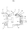
- FIGs. 10(a) and 10(b) illustrate an example of a conventional support structure for ink cartridge.
- ink cartridges 21 are supported firmly by being pressed from front to rear, from side to side, and from top to bottom, by a carriage 22.
- the carriage 22 is guided by a guide shaft 22a which is mounted on a frame of an apparatus body, so as to be reciprocatable in a main scanning direction.
- the support structure is "2-pen" type, i.e., the structure holds the two ink cartridges 21, 21 in alignment.
- the ink cartridges 21 are pressed from top to bottom by an upper pressure member 27.
- the upper pressure member 27 is rotatably attached to an upper cover 24 which is pivotably connected to the carriage 22.
- the ink cartridges 21 are also pressed from front to rear, i.e., from right to left in FIG. 10(b), by a front pressure member 26 which is attached to the carriage 22.
- the ink cartridges 21 are pressed from left to right, i.e., from a near side to a far side of a sheet of FIG. 10(b) along a direction perpendicular to the sheet.
- a dashed double-dotted line depicts an open state of the front pressure member 26 and the upper pressure member 27.
- a pressure mechanism is provided for each of the ink cartridges 21.
- the front pressure member 26 projecting at the front of the cover 24 is an obstacle in mounting or dismounting the cartridges 21 in a downward or upward direction. Furthermore, the lateral pressure member 28 still presses the ink cartridges 21 from leftwards, thereby preventing the cartridges 21 from being dismounted smoothly.
- the conventional support structure for ink cartridge prevents smooth mounting and dismounting of the ink cartridges 21.
- a feature of the present invention is to offer a durable support structure for ink cartridge allowing smooth mounting and dismounting of ink cartridge, as well as simplified assembly and adjustment operations of components.
- the detecting member prevents troubles caused by mismounting of ink cartridge.
- FIGs. 1(a) to 1(c) are views illustrating construction of relevant parts of an inkjet printer according to the embodiment.
- FIG. 1(a) is a top view
- FIG. 1(b) is a front elevational view
- FIG. 1(c) is a left side view, of the relevant parts.
- an ink cartridge 1 is integrated with a not-shown one-pen print head.
- a carriage 2 is provided for supporting the ink cartridge 1 while reciprocating in a main scanning direction.
- the carriage 2 is made of, for example, synthetic resin.
- a frame (main chassis) 3 is provided in order for components of the inkjet printer to be mounted thereon.
- the frame 3 is attached to a body of the printer and is made of, for example, a galvanized steel plate.
- a guide shaft 4 is provided for stable guidance of the carriage 2 in the main scanning direction.
- the guide shaft 4 is made of, for example, stainless steel.
- the carriage 2 with the ink cartridge 1 detachably mounted thereon is guided reciprocably in a direction of arrow X, i.e., in a main scanning direction, on the frame 3 and on the guide shaft 4.
- a direction of arrow X i.e., in a main scanning direction
- ink droplets are sprayed on a print medium (sheet) being transported in a direction of arrow Y, i.e., in a sheet transport direction, by not shown transport rollers.
- sheet transport direction is perpendicular to the main scanning direction.
- FIG. 2 is a top view of the carriage 2 with a front cover and an upper cover both opened.
- FIG. 3 is a top view of the carriage with the front cover and the upper cover both closed.
- FIG. 4 is a right side view of the carriage with the front cover and the upper cover both closed.
- FIG. 5 is a left side view of the carriage with the front cover and the upper cover both closed.
- the carriage 2 has a rear wall 2a, a first lateral wall 2b, and a base 2c.
- a front cover 5 for holding the ink cartridge 1 is connected pivotably to the carriage 2 through a spindle 5a and a front cover release spring 5b.
- a front pressure member 6 is provided at an inner part of the front cover 5 .
- the front pressure member 6 presses a front surface of the ink cartridge 1, so that a rear surface thereof is pressed firmly against the rear wall 2a.
- An upper cover 7 is attached to the carriage 2 through a spindle 7a and an upper cover release spring 7b so as to be pivotable, i.e., openable and closeable in a vertical direction.
- the upper cover 7 presses a top surface of the ink cartridge 1 toward a bottom surface thereof.
- a detecting rib (detecting member) 7d integrated with the upper cover 7 is provided for detecting whether a proper ink cartridge is mounted on the carriage 2.
- an upper pressure member 8 Provided at an inner part of the upper cover 7 is an upper pressure member 8 made of an elastic member such as a piece of rubber or a plate spring.
- a lateral pressure member 9 made of an elastic member such as a piece of rubber or a plate spring. With the ink cartridge 1 mounted on the carriage 2, the lateral pressure member 9 presses a left lateral surface of the ink cartridge 1, so that a right lateral surface thereof is pressed firmly against the first lateral wall 2b.
- a lock lever 10 is pivotably attached to a corner part of an open end of the front cover 5. When the ink cartridge 1 is to be replaced, the lock lever 10 is unlatched from, and latched again to, a front-end part of the first lateral wall 2b.
- the front cover 5 is formed in the shape of the letter L, as in FIG. 2.
- the cover 5 includes a base having a not-shown connecting portion.
- the cover 5 is connected pivotably, i.e., openably and closably in a horizotal direction, at the base to the carriage 2 through the spindle 5a and the front cover release spring 5b.
- a solid line and a double-dotted dashed line depict a closed state and an open state, respectively, of the cover 5.
- the front pressure member 6 provided at the inner part of the front cover 5 is elastically biased by the elastic member such as a plate spring. With the ink cartridge 1 mounted, the front pressure member 6 presses the front surface of the ink cartridge 1, so that the rear surface thereof is pressed firmly against the rear wall 2a.
- the front pressure member 6 is attached pivotably at a top part thereof to the front cover 5 through the spindle 6a. A lower portion of the member 6 is elastically biased towards the rear wall 2a by a plate spring 6b.
- the upper cover 7 has a base which includes a not-shown connecting portion.
- the cover 7 is connected pivotably, i.e., openably and closably in a vertical direction, at the base to the carriage 2 through an upper cover engaging cam 7d provided in the spindle 7a.
- the upper pressure member 8 provided at the inner part of the upper cover 7 presses the top surface of the ink cartridge 1 toward the bottom surface thereof.
- the bottom surface is thus stably situated on the base 2c.
- a solid line and a double-dotted dashed line depict a closed state and an open state, respectively, of the upper cover 7.
- the lateral pressure member 9 provided at the inner part of the front cover 5 presses the left lateral surface of the ink cartridge 1, so that the right lateral surface thereof is pressed firmly against the first lateral wall 2b.
- the carriage 2 supports firmly the ink cartridge 1 as mounted by pressing the cartridge 1 from front to rear, from top to bottom, and from side to side. This serves to avoid jounce of the ink cartridge 1 during scanning movement of the carriage 2, thereby ensuring electric continuity between the carriage 2 and the ink cartridge 1 and thus a constant high-quality level of printing.
- the lock lever 10 When the ink cartridge 1 is to be replaced, the lock lever 10 is operated to open the front cover 5. The operation of the lock lever 10 automatically causes a not-shown torsion spring to act to open the front cover 5. Then, the upper cover 7 is opened automatically, as shown in FIGs. 7(a) and 7(b), because the respective connecting portions provided in the spindle 5a and the spindle 7a are connected to each other through a transmission mechanism using a bevel gear or a cam.
- the lateral pressure member 9 provided at the inner part of the front cover 5 presses the left lateral surface of the ink cartridge 1, and a reaction force is thus exerted on the pressure member 9.
- the reaction force facilitates the opening operation of the cover 5 from the ink cartridge 1.
- the ink cartridge 1 With the cover 5 opened, there is no obstacle, in the front, left, and top sides of the ink cartridge 1, in dismounting the cartridge 1. Accordingly, the ink cartridge 1 is dismounted smoothly without being damaged. Likewise, the ink cartridge 1 is mounted smoothly with no obstacle in the front, left, and top sides thereof.
- the front cover 5 is connected openably and closably to the left side of the carriage 2.
- the cover 5 may be connected openably and closably to the right side of the carriage 2.
- the first lateral wall 2b is provided on the left side of the carriage 2 so that a left lateral surface of the ink cartridge 1 is pressed against the wall 2b.
- FIG. 6 is a front elevational view of the carriage with the front cover and the upper cover both closed.
- the lateral pressure member 9 which is provided at the inner part of the front cover 5, presses the left lateral surface of the ink cartridge 1, so that the right lateral surface thereof is pressed firmly against the first lateral wall 2b.
- the cover 5 With the cover 5 open, therefore, there is ensured upper and front space sufficient for replacing the ink cartridge 1.
- FIGs. 7(a) to 7(b) are views illustrating how the front cover and the upper cover of the carriage operate in conjunction with each other.
- the front cover and the upper cover are both open.
- the front cover and the upper cover are both closed.
- the front cover 5 and the upper cover 7 are respectively integrated with not-shown separate rotating shafts.
- a front cover engaging cam 5c and an upper cover engaging cam 7c are provided on the shafts.
- the upper cover release spring 7b elastically biases the upper cover 7 in such a direction as to open the cover 7.
- the upper cover release spring 7b elastically biases the upper cover 7 in such a direction as to close the cover 7.
- a force exerted on the cover 5 acts to open the cover 7.
- the front cover 5 may be opened or closed in conjunction with the cover 7 by the cam mechanism including the the engaging cams 5c and 7c.
- either one of the front cover 5 and the upper cover 7 is opened or closed in conjunction with the open/close operation of the other. This allows smooth mounting or dismounting of the ink cartridge 1.
- Substitutable for the cam mechanism is a bevel-gear mechanism.
- An example of such bevel-gear mechanism is a mechanism including bevel gears which are provided on the spindle 5a and the spindle 7c, respectively, so as to be meshed with each other.
- the bevel-gear mechanism eliminates the need for a spring for elastically biasing either one of the cover 5 and the cover 7.
- the bevel-gear mechanism unlike the cam mechanism, involves complicated operation processes of assembling and adjusting the carriage 2, with a potential decrease in durability of the carriage 2.
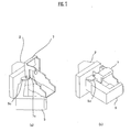
- FIGs. 8(a), 8(b), 9(a), and 9(b) are views illustrating how the detecting member according to another embodiment of the present invention detects whether an ink cartridge as mounted is a proper one.
- FIGs. 8(a) and 8(b) Illustrated in FIGs. 8(a) and 8(b) is a case in which the ink cartridge 1 as mounted is a proper one.
- the upper cover 7 has detecting ribs 7d, which correspond to the detecting members of the present invention, provided on a reverse side thereof.
- the ribs 7d fit into corresponding slots in a detecting device 1a provided in a top part of the proper ink cartridge 1, so that the cover 7 is closed properly, as shown in the figures. Consequently, the ink cartridge 1 is mounted properly.
- FIGs. 9(a) and 9(b) Illustrated in FIGs. 9(a) and 9(b) is a case in which the ink cartridge 1 to be mounted is an improper one.
- the detecting ribs 7d do not fit the slots in the detecting device 1a, so that the cover 7 cannot be closed properly. In other words, the ink cartridge 1 cannot be mounted properly. This allows detection of the ink cartridge 1 being improper.
- the detecting device 1a and the detecting ribs 7d to fit in the device 1a are configured to detect whether the ink cartridge 1 is a proper one.
- the present invention is not limited to what is described in the present embodiment.
- An alternative device such as an electric contact structure or a photosensor may be provided for detecting whether the ink cartridge 1 is a proper one.
- the front pressure member 6 and the lateral pressure member 9 provided in the front cover 5, and the upper pressure member 8 provided in the upper cover 7 may be omitted.
- a projecting portion for pressing the surface of the ink cartridge 1 should be formed in each of the front inner side and lateral inner side of the front cover 5 and in the inner side of the upper cover 7. It is preferable that the projecting portions have appropriate elasticity.
- the present invention has the following advantageous features.
Landscapes
- Ink Jet (AREA)
Abstract
Description
Claims (8)
- A support structure for ink cartridge provided detachably in an ink jet printing apparatus, comprising:a carriage for reciprocating in a main scanning direction, the carriage including a rear wall for supporting a rear surface of the ink cartridge, a base for supporting a bottom surface of the ink cartridge, and a first lateral wall for supporting a first lateral surface of the ink cartridge;a front cover connected to the carriage openably and closably in a horizontal direction, the front cover pressing a front surface of the ink cartridge toward the rear surface and pressing a second lateral surface of the ink cartridge toward the first lateral surface thereof; andan upper cover connected to the carriage openably and closably in a vertical direction, the upper cover pressing a top surface of the ink cartridge toward the bottom surface.
- A support structure for ink cartridge according to claim 1, wherein the front cover has a front pressure member for pressing the front surface of the ink cartridge toward the rear surface thereof.
- A support structure for ink cartridge according to claim 1, wherein the front cover has a lateral pressure member for pressing the second lateral surface of the ink cartridge toward the first lateral surface thereof.
- A support structure for ink cartridge according to claim 1, wherein the upper cover has an upper pressure member for pressing the top surface of the ink cartridge toward the bottom surface thereof.
- A support structure for ink cartridge according to claim 1, wherein the front cover and the upper cover are connected to move in conjunction with each other, so that open and close operation of either one of the front cover and the upper cover involves open and close operation of the other one.
- A support structure for ink cartridge according to claim 5, wherein the front cover and the upper cover are connected to move in conjunction with each other through a bevel-gear mechanism.
- A support structure for ink cartridge according to claim 5, wherein the front cover and the upper cover are connected to move in conjunction with each other through a cam mechanism.
- A support structure for ink cartridge according to claim 1, wherein the upper cover includes a detecting member for detecting whether an ink cartridge as mounted is a proper one.
Applications Claiming Priority (5)
| Application Number | Priority Date | Filing Date | Title |
|---|---|---|---|
| JP2002296309 | 2002-10-09 | ||
| JP2002296309 | 2002-10-09 | ||
| JP2002372701A JP2004181918A (en) | 2002-10-09 | 2002-12-24 | Ink cartridge holding structure |
| JP2002372701 | 2002-12-24 | ||
| PCT/JP2003/012814 WO2004033215A1 (en) | 2002-10-09 | 2003-10-07 | Structure for holding ink cartridge |
Publications (3)
| Publication Number | Publication Date |
|---|---|
| EP1557271A1 true EP1557271A1 (en) | 2005-07-27 |
| EP1557271A4 EP1557271A4 (en) | 2008-09-17 |
| EP1557271B1 EP1557271B1 (en) | 2010-04-14 |
Family
ID=32095417
Family Applications (1)
| Application Number | Title | Priority Date | Filing Date |
|---|---|---|---|
| EP03751351A Expired - Lifetime EP1557271B1 (en) | 2002-10-09 | 2003-10-07 | Structure for holding ink cartridge |
Country Status (6)
| Country | Link |
|---|---|
| US (1) | US7275809B2 (en) |
| EP (1) | EP1557271B1 (en) |
| JP (1) | JP2004181918A (en) |
| AU (1) | AU2003271109A1 (en) |
| DE (1) | DE60332143D1 (en) |
| WO (1) | WO2004033215A1 (en) |
Cited By (1)
| Publication number | Priority date | Publication date | Assignee | Title |
|---|---|---|---|---|
| EP3144155A1 (en) * | 2015-09-16 | 2017-03-22 | Funai Electric Co., Ltd. | Image forming apparatus |
Families Citing this family (8)
| Publication number | Priority date | Publication date | Assignee | Title |
|---|---|---|---|---|
| TWI280196B (en) * | 2005-10-21 | 2007-05-01 | Lite On Technology Corp | Ink cartridge loading mechanism |
| JP4668802B2 (en) * | 2006-02-09 | 2011-04-13 | 船井電機株式会社 | Image forming apparatus |
| CN2931122Y (en) * | 2006-07-25 | 2007-08-08 | 聂瑞权 | An inkjet printer ink cartridge with a handle |
| US8152287B2 (en) * | 2007-08-31 | 2012-04-10 | Brother Kogyo Kabushiki Kaisha | Ink cartridge assemblies |
| JP5169324B2 (en) * | 2008-03-05 | 2013-03-27 | 株式会社リコー | Image forming apparatus |
| JP5253034B2 (en) * | 2008-08-07 | 2013-07-31 | キヤノン株式会社 | Recording device |
| JP5727720B2 (en) | 2010-03-31 | 2015-06-03 | 富士通コンポーネント株式会社 | Printer |
| US12565047B2 (en) | 2023-10-06 | 2026-03-03 | Brady Worldwide, Inc. | Carriage for fluid ejection cartridge |
Family Cites Families (10)
| Publication number | Priority date | Publication date | Assignee | Title |
|---|---|---|---|---|
| JP2002292890A (en) * | 2001-03-30 | 2002-10-09 | Brother Ind Ltd | ink cartridge |
| US5392063A (en) * | 1993-04-30 | 1995-02-21 | Hewlett-Packard Company | Spring cartridge clamp for inkjet printer carriage |
| IT1286298B1 (en) * | 1995-04-05 | 1998-07-08 | Seiko Epson Corp | INK-JET RECORDING EQUIPMENT. |
| US6286934B1 (en) * | 1997-09-26 | 2001-09-11 | Brother Kogyo Kabushiki Kaisha | Ink jet printer including detachable print cartridge |
| EP1514689B1 (en) * | 1998-05-18 | 2006-11-08 | Seiko Epson Corporation | Ink cartridge for an ink-jet printing apparatus |
| US6364458B2 (en) * | 1999-02-18 | 2002-04-02 | Hewlett-Packard Company | Pivoted printhead handle with recessed rest position |
| JP3821197B2 (en) | 1999-09-30 | 2006-09-13 | セイコーエプソン株式会社 | Carriage and inkjet recording apparatus |
| JP2002254670A (en) | 2001-03-02 | 2002-09-11 | Seiko Epson Corp | Carriage and inkjet recording device |
| US6481829B1 (en) * | 2001-09-18 | 2002-11-19 | Lexmark International, Inc. | Manually actuated carrier latch mechanism |
| JP2003334935A (en) * | 2002-03-15 | 2003-11-25 | Sharp Corp | Recording device |
-
2002
- 2002-12-24 JP JP2002372701A patent/JP2004181918A/en active Pending
-
2003
- 2003-10-07 EP EP03751351A patent/EP1557271B1/en not_active Expired - Lifetime
- 2003-10-07 DE DE60332143T patent/DE60332143D1/en not_active Expired - Lifetime
- 2003-10-07 AU AU2003271109A patent/AU2003271109A1/en not_active Abandoned
- 2003-10-07 WO PCT/JP2003/012814 patent/WO2004033215A1/en not_active Ceased
- 2003-10-07 US US10/530,526 patent/US7275809B2/en not_active Expired - Fee Related
Non-Patent Citations (2)
| Title |
|---|
| No further relevant documents disclosed * |
| See also references of WO2004033215A1 * |
Cited By (1)
| Publication number | Priority date | Publication date | Assignee | Title |
|---|---|---|---|---|
| EP3144155A1 (en) * | 2015-09-16 | 2017-03-22 | Funai Electric Co., Ltd. | Image forming apparatus |
Also Published As
| Publication number | Publication date |
|---|---|
| JP2004181918A (en) | 2004-07-02 |
| EP1557271B1 (en) | 2010-04-14 |
| WO2004033215A1 (en) | 2004-04-22 |
| DE60332143D1 (en) | 2010-05-27 |
| EP1557271A4 (en) | 2008-09-17 |
| AU2003271109A1 (en) | 2004-05-04 |
| US7275809B2 (en) | 2007-10-02 |
| US20060066694A1 (en) | 2006-03-30 |
Similar Documents
| Publication | Publication Date | Title |
|---|---|---|
| US8764163B2 (en) | Inkjet recording device having waste liquid chamber | |
| US8985720B2 (en) | Recording apparatus | |
| US7694951B2 (en) | Sheet feeder including a plurality of paper cassettes | |
| TWI546203B (en) | Complex apparatus | |
| JP3217610B2 (en) | Ink jet recording device and information processing system | |
| US7275809B2 (en) | Structure for holding ink cartridge | |
| US7692825B2 (en) | Sheet supplying apparatus and image recording apparatus including same | |
| US7654515B2 (en) | Image forming device with two attached cassettes and one transportation device | |
| JP3767568B2 (en) | Image forming apparatus | |
| JP2003053999A (en) | Image forming device | |
| US7628558B2 (en) | Transport system, recording apparatus and liquid ejection apparatus | |
| JP2000158663A (en) | Ink jet recording device | |
| CN100341706C (en) | Structure for holding ink cartridge | |
| JP2004017314A (en) | Inkjet image forming equipment | |
| JP2006205537A (en) | Support structure for moving body, and recording apparatus and liquid ejecting apparatus having the support structure | |
| JP2003053947A (en) | Image forming device | |
| US20260021669A1 (en) | Printing apparatus | |
| JP2001096726A (en) | Ink jet recording device | |
| JP2007175911A (en) | Roll paper printer | |
| US7461915B2 (en) | Inkjet recording apparatus | |
| JP4433161B2 (en) | Inkjet recording device | |
| JPH03203650A (en) | Ink jet recorder | |
| JP2004058356A (en) | Printer | |
| JP2026013219A (en) | Recording device | |
| JPH11321006A (en) | Serial recording device |
Legal Events
| Date | Code | Title | Description |
|---|---|---|---|
| PUAI | Public reference made under article 153(3) epc to a published international application that has entered the european phase |
Free format text: ORIGINAL CODE: 0009012 |
|
| 17P | Request for examination filed |
Effective date: 20050506 |
|
| AK | Designated contracting states |
Kind code of ref document: A1 Designated state(s): AT BE BG CH CY CZ DE DK EE ES FI FR GB GR HU IE IT LI LU MC NL PT RO SE SI SK TR |
|
| AX | Request for extension of the european patent |
Extension state: AL LT LV MK |
|
| DAX | Request for extension of the european patent (deleted) | ||
| RBV | Designated contracting states (corrected) |
Designated state(s): DE GB |
|
| A4 | Supplementary search report drawn up and despatched |
Effective date: 20080818 |
|
| 17Q | First examination report despatched |
Effective date: 20081111 |
|
| GRAP | Despatch of communication of intention to grant a patent |
Free format text: ORIGINAL CODE: EPIDOSNIGR1 |
|
| GRAS | Grant fee paid |
Free format text: ORIGINAL CODE: EPIDOSNIGR3 |
|
| GRAA | (expected) grant |
Free format text: ORIGINAL CODE: 0009210 |
|
| AK | Designated contracting states |
Kind code of ref document: B1 Designated state(s): DE GB |
|
| REG | Reference to a national code |
Ref country code: GB Ref legal event code: FG4D |
|
| REF | Corresponds to: |
Ref document number: 60332143 Country of ref document: DE Date of ref document: 20100527 Kind code of ref document: P |
|
| PLBE | No opposition filed within time limit |
Free format text: ORIGINAL CODE: 0009261 |
|
| STAA | Information on the status of an ep patent application or granted ep patent |
Free format text: STATUS: NO OPPOSITION FILED WITHIN TIME LIMIT |
|
| 26N | No opposition filed |
Effective date: 20110117 |
|
| PGFP | Annual fee paid to national office [announced via postgrant information from national office to epo] |
Ref country code: DE Payment date: 20131002 Year of fee payment: 11 Ref country code: GB Payment date: 20131002 Year of fee payment: 11 |
|
| REG | Reference to a national code |
Ref country code: DE Ref legal event code: R119 Ref document number: 60332143 Country of ref document: DE |
|
| GBPC | Gb: european patent ceased through non-payment of renewal fee |
Effective date: 20141007 |
|
| PG25 | Lapsed in a contracting state [announced via postgrant information from national office to epo] |
Ref country code: GB Free format text: LAPSE BECAUSE OF NON-PAYMENT OF DUE FEES Effective date: 20141007 Ref country code: DE Free format text: LAPSE BECAUSE OF NON-PAYMENT OF DUE FEES Effective date: 20150501 |