EP1556858B1 - Spherical aberration detection - Google Patents
Spherical aberration detection Download PDFInfo
- Publication number
- EP1556858B1 EP1556858B1 EP03809394A EP03809394A EP1556858B1 EP 1556858 B1 EP1556858 B1 EP 1556858B1 EP 03809394 A EP03809394 A EP 03809394A EP 03809394 A EP03809394 A EP 03809394A EP 1556858 B1 EP1556858 B1 EP 1556858B1
- Authority
- EP
- European Patent Office
- Prior art keywords
- radiation beam
- focus error
- error signal
- spherical aberration
- radiation
- Prior art date
- Legal status (The legal status is an assumption and is not a legal conclusion. Google has not performed a legal analysis and makes no representation as to the accuracy of the status listed.)
- Expired - Lifetime
Links
- 230000004075 alteration Effects 0.000 title claims abstract description 58
- 238000001514 detection method Methods 0.000 title description 8
- 230000005855 radiation Effects 0.000 claims abstract description 164
- 230000003287 optical effect Effects 0.000 claims abstract description 52
- 210000002858 crystal cell Anatomy 0.000 claims description 15
- 239000004973 liquid crystal related substance Substances 0.000 claims description 15
- 238000000034 method Methods 0.000 claims description 6
- 238000005259 measurement Methods 0.000 description 14
- 230000010363 phase shift Effects 0.000 description 3
- 238000004519 manufacturing process Methods 0.000 description 2
- 239000000969 carrier Substances 0.000 description 1
- 239000012876 carrier material Substances 0.000 description 1
- 230000021615 conjugation Effects 0.000 description 1
- 230000009977 dual effect Effects 0.000 description 1
- 230000005684 electric field Effects 0.000 description 1
- 230000001939 inductive effect Effects 0.000 description 1
- 230000002093 peripheral effect Effects 0.000 description 1
- 239000004065 semiconductor Substances 0.000 description 1
- 230000001360 synchronised effect Effects 0.000 description 1
Images


Classifications
-
- G—PHYSICS
- G11—INFORMATION STORAGE
- G11B—INFORMATION STORAGE BASED ON RELATIVE MOVEMENT BETWEEN RECORD CARRIER AND TRANSDUCER
- G11B7/00—Recording or reproducing by optical means, e.g. recording using a thermal beam of optical radiation by modifying optical properties or the physical structure, reproducing using an optical beam at lower power by sensing optical properties; Record carriers therefor
- G11B7/12—Heads, e.g. forming of the optical beam spot or modulation of the optical beam
- G11B7/135—Means for guiding the beam from the source to the record carrier or from the record carrier to the detector
- G11B7/1362—Mirrors
-
- G—PHYSICS
- G11—INFORMATION STORAGE
- G11B—INFORMATION STORAGE BASED ON RELATIVE MOVEMENT BETWEEN RECORD CARRIER AND TRANSDUCER
- G11B7/00—Recording or reproducing by optical means, e.g. recording using a thermal beam of optical radiation by modifying optical properties or the physical structure, reproducing using an optical beam at lower power by sensing optical properties; Record carriers therefor
- G11B7/12—Heads, e.g. forming of the optical beam spot or modulation of the optical beam
- G11B7/125—Optical beam sources therefor, e.g. laser control circuitry specially adapted for optical storage devices; Modulators, e.g. means for controlling the size or intensity of optical spots or optical traces
- G11B7/126—Circuits, methods or arrangements for laser control or stabilisation
-
- G—PHYSICS
- G02—OPTICS
- G02B—OPTICAL ELEMENTS, SYSTEMS OR APPARATUS
- G02B27/00—Optical systems or apparatus not provided for by any of the groups G02B1/00 - G02B26/00, G02B30/00
- G02B27/0025—Optical systems or apparatus not provided for by any of the groups G02B1/00 - G02B26/00, G02B30/00 for optical correction, e.g. distorsion, aberration
-
- G—PHYSICS
- G11—INFORMATION STORAGE
- G11B—INFORMATION STORAGE BASED ON RELATIVE MOVEMENT BETWEEN RECORD CARRIER AND TRANSDUCER
- G11B7/00—Recording or reproducing by optical means, e.g. recording using a thermal beam of optical radiation by modifying optical properties or the physical structure, reproducing using an optical beam at lower power by sensing optical properties; Record carriers therefor
- G11B7/08—Disposition or mounting of heads or light sources relatively to record carriers
- G11B7/09—Disposition or mounting of heads or light sources relatively to record carriers with provision for moving the light beam or focus plane for the purpose of maintaining alignment of the light beam relative to the record carrier during transducing operation, e.g. to compensate for surface irregularities of the latter or for track following
- G11B7/0945—Methods for initialising servos, start-up sequences
-
- G—PHYSICS
- G11—INFORMATION STORAGE
- G11B—INFORMATION STORAGE BASED ON RELATIVE MOVEMENT BETWEEN RECORD CARRIER AND TRANSDUCER
- G11B7/00—Recording or reproducing by optical means, e.g. recording using a thermal beam of optical radiation by modifying optical properties or the physical structure, reproducing using an optical beam at lower power by sensing optical properties; Record carriers therefor
- G11B7/12—Heads, e.g. forming of the optical beam spot or modulation of the optical beam
- G11B7/135—Means for guiding the beam from the source to the record carrier or from the record carrier to the detector
- G11B7/1365—Separate or integrated refractive elements, e.g. wave plates
- G11B7/1369—Active plates, e.g. liquid crystal panels or electrostrictive elements
-
- G—PHYSICS
- G11—INFORMATION STORAGE
- G11B—INFORMATION STORAGE BASED ON RELATIVE MOVEMENT BETWEEN RECORD CARRIER AND TRANSDUCER
- G11B7/00—Recording or reproducing by optical means, e.g. recording using a thermal beam of optical radiation by modifying optical properties or the physical structure, reproducing using an optical beam at lower power by sensing optical properties; Record carriers therefor
- G11B7/12—Heads, e.g. forming of the optical beam spot or modulation of the optical beam
- G11B7/135—Means for guiding the beam from the source to the record carrier or from the record carrier to the detector
- G11B7/1392—Means for controlling the beam wavefront, e.g. for correction of aberration
- G11B7/13925—Means for controlling the beam wavefront, e.g. for correction of aberration active, e.g. controlled by electrical or mechanical means
- G11B7/13927—Means for controlling the beam wavefront, e.g. for correction of aberration active, e.g. controlled by electrical or mechanical means during transducing, e.g. to correct for variation of the spherical aberration due to disc tilt or irregularities in the cover layer thickness
Definitions
- the present invention relates to an optical device comprising means for detecting a spherical aberration.
- the present invention also relates to a method for detecting a spherical aberration.
- the present invention is particularly relevant for an optical disc apparatus for reading and/or recording data from and/or to an optical disc, e.g. a CD, a DVD or a Blu-Ray Disc (BD) player and/or recorder.
- an optical disc e.g. a CD, a DVD or a Blu-Ray Disc (BD) player and/or recorder.
- BD Blu-Ray Disc
- An optical device comprising means for detecting a spherical aberration is known from Applicant's US 6,229,600 .
- the invention described in this patent aims at providing a detection system for detecting a spherical aberration.
- a detection system is used in an optical device comprising means for focussing a radiation beam on an information carrier.
- Information carriers are often scanned through a transparent layer protecting an information layer.
- a small variation of the thickness of the transparent layer causes a substantial change in the spherical aberration incurred by a high-numerical aperture radiation beam traversing the transparent layer.
- This spherical aberration might be reduced, by using, for example, a dual lens objective, as described in US 6,229,600 . But the amount of spherical aberration might be determined in order to be able to reduce the spherical aberration.
- Fig.1 illustrates how the spherical aberration is detected in an optical device, according to US 6,229,600 .
- the optical device comprises a radiation source 101 controlled by a driver 113, a collimator lens 102, an objective lens 103, a plano-convex lens 104, a beam-splitter 105, two detectors 106 and 107, a signal processor 108, an adder 109, an amplifier 110, and two servo controllers 111 and 112.
- This optical device is intended for scanning an information carrier 100.
- the radiation source 101 produces a radiation beam, which is focussed on an information layer of the information carrier 100 thanks to the collimator lens 102 and the objective lens 103.
- the radiation beam is reflected by the information layer and is transformed to a converging radiation beam by the objective lens 103 and the collimator lens 102.
- Part of this converging radiation beam incident on a central zone of the beam splitter 105 is deflected towards detector 106 and part of this converging radiation beam incident on an outer zone of the beam splitter 105 is deflected towards detector 107.
- the signal detected by detectors 106 and 107 allows the signal processor 108 to provide focus error signals corresponding to the inner part and the outer part of the reflected radiation beam.
- the signal processor 108 also determines the spherical aberration of the radiation beam by subtracting these two focus error signals.
- the servo controller111 drives an actuator controlling the axial position of the objective lens 103 in order to correct the focus error.
- the servo controller 112 drives an actuator controlling the axial position of the plano-convex lens 104 in order to correct the spherical aberration.
- a disadvantage of the optical device described above lies in the fact that it requires a special beam splitter 105, which makes the optical device bulky and complicated.
- Another disadvantage lies in the fact that it requires two detectors, which make the optical device bulky and complicated, as these two detectors require a different readout channel, comprising different associated electronics.
- EP 1215667 A2 discloses an optical head for use in an optical data recording/reproducing apparatus.
- Light issued from a semiconductor laser is split into a main beam that is zeroth order light and subbeams that are positive and negative first-order diffracted light.
- a focus error signal is detected from each of the main beam and subbeams.
- a diffraction optical element causes the main beam and subbeams to differ in light intensity distribution from each other when incident to an object lens.
- the focus error signal derived from the main beam and focus error signals derived from the subbeams differ in zero-crossing point from each other.
- the thickness error is detected on the basis of the difference between the zero-crossing points.
- the invention proposes an optical device comprising means for focussing a first radiation beam having a first numerical aperture and a second radiation beam having a second numerical aperture different from the first numerical aperture, on an information carrier, means for switchip between the first radiation beam and the second radiation (beam) means for detecting a first focus error signal corresponding to the first radiation beam and a second focus error signal corresponding to the second radiation beam, and means for measuring a spherical aberration of the first radiation beam from the first and second focus error signals, wherein said means for focussing said first and second radiation beam are adapted for non-simultaneously focussing said first radiation beam and said second radiation beam on said information carrier.
- the invention is based on the recognition that, in a radiation beam having spherical aberration, the rays in the centre of the beam and the rays at the periphery of the beam have different focal points, when focussed on an information carrier.
- the difference between the positions of the focal points provides a measure of the spherical aberration.
- the rays in the centre of the beam have a numerical aperture which is lower than the numerical aperture of the rays at the periphery of the beam.
- a measurement of the spherical aberration can be obtained by detecting the difference in the positions of the focal points of two radiation beams having different numerical apertures, these two radiation beams being focussed on the information carrier.
- no beam-splitter is needed in such an optical device, which simplifies the device.
- the first and second radiation beams are produced by two radiation sources
- the device further comprises means for switching on and off the radiation beams
- the first and second focus error signals are detected by a same detector.
- two radiation sources are used in order to produce the two radiation beams having different numerical apertures.
- One of the radiation beams for example a blue laser
- the other radiation beam which is for example intended to scan a DVD, is used to provide a measurement of the spherical aberration.
- the first radiation beam is switched off and the second radiation beam is switched on
- a measurement of the focus error signal of the second radiation beam and then of the spherical aberration is performed, after which the second radiation beam is switched off and the first radiation beam is switched on in order to scan the information layer.
- a same detector is used to detect the focus error signals corresponding to the two radiation beams.
- the optical device further comprises means for pulsing the second radiation beam and means for detecting a pulsed focus error signal corresponding to said pulsed second radiation beam.
- the first and second radiation beams are produced by a same radiation source
- the optical device further comprises means for reducing the numerical aperture of the first radiation beam in order to obtain the second radiation beam, and means for switching on and off said reducing means.
- the second radiation beam which is used for measuring the spherical aberration, is part of the first radiation beam.
- This embodiment is advantageously used in optical devices, where only one radiation source is available.
- a liquid crystal cell is placed between the radiation source and the focussing means in order to reduce the numerical aperture of the first radiation beam.
- a liquid crystal cell is easily and rapidly switchable, thanks to electric fields.
- constructing the second radiation beam from the first radiation beam is easy.
- the liquid crystal cell can be switched on and off in a pulsed way, which leads to a pulsed second radiation beam, thus improving the signal to noise ratio.
- the invention also relates to a method for detecting a spherical aberration, said method comprising the steps of:
- the step of measuring a spherical aberration of the first radiation beam from the first and second focus error signals is performed by calculating the difference between the first focus error signal and the second focus error signal, and subtracting a predefined focus error signal from said difference, said predefined focus errorsignal corresponding to a focus error signal obtained with the second radiation beam focussed on an information carrier having a predetermined thickness.
- a predefined focus error signal is taken into account, which corresponds to a focus error signal obtained with the second radiation beam focussed on an information carrier having a predetermined thickness.
- the second radiation beam has a focus error, because the information carrier is intended to be read by the first radiation beam.
- This predefined focus error signal might be determined during a manufacturing process, and loaded in a memory of the optical device, in order to be subtracted from the difference between the first focus error signal and the second focus error signal.
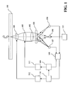
- FIG.2 An optical device according to a preferred embodiment of the invention is depicted in Fig.2 .
- Such an optical device comprises a first radiation source 201 for producing a first radiation beam 203, a second radiation source 202 for producing a second radiation beam 204, a first beam splitter 205, a collimator lens 206, a second beam splitter 207, an objective lens 208, a plano-convex lens 209, a servo lens 210, detecting means 211, measuring means 212 and two servo controllers 213 and 214.
- This optical device is intended for scanning an information carrier 200.
- the information carrier 200 is a Blu-ray disc comprising an information layer.
- this Blu-ray disc is scanned by the first radiation beam 203 produced by the first radiation source 201.
- the first radiation beam 203 has a first wavelength equal to 405 nanometres.
- the collimator lens 206 and the objective lens 208 focus the first radiation beam 203 on the information layer of the information carrier 200.
- the collimator lens 206 and the objective lens 208 are focussing means.
- the numerical aperture of the first radiation beam is 0.85.
- a first focus error signal might be detected, corresponding to the first radiation beam 203.
- This first focus error signal might be used to correct the axial position of the objective lens 208 in order to compensate for a focus error signal of the first radiation beam 203.
- a signal is sent to the servo controller 213, which drives an actuator in order to move the objective lens 208 axially.
- the first focus error signal is detected by the detecting means 211.
- the first radiation beam 203, reflected by the information carrier 200, is transformed to a parallel beam by the objective lens 208, and then reaches the servo lens 210, thanks to the second beam splitter 207.
- This reflected beam then reaches the detecting means 211, which detects a first focus error signal, based on any focus detection method known in the art.
- the astigmatic focus detection method or the Foucault detection method might be used. These focus detection methods are described, for example, in US 6,229,600 .
- the detecting means 211 are preferably placed in the optical device by using a first radiation beam 203 without spherical aberration. In order to place the detecting means, a ⁇ perfect' disc having a calibrated cover layer thickness of 100 micrometers is used.
- the first radiation beam 203 is switched off, for example by switching off the first radiation source 201.
- the second radiation beam 204 is then switched on.
- This second radiation beam 204 is sent to the collimator lens 206, thanks to the first beam splitter 205.
- the second radiation beam 204 is then transformed to a parallel beam by the collimator lens 206 and focussed on the information carrier 200, thanks to the objective lens 208.
- the numerical aperture of this second radiation beam 204 is 0.65 and the wavelength of the second radiation beam 204 is 650 nanometres.
- This second radiation beam 204 is usually used for scanning a DVD.
- the second radiation beam 204 reflected by the information carrier 200, is transformed to a parallel beam by the objective lens 208 and then reaches the servo lens 210, thanks to the second beam splitter 207. This reflected beam then reaches the detecting means 211, which detects a second focus error signal, as described above for the first radiation beam 203.
- the measuring means 212 performs a difference between the first focus error signal and the second focus error signal.
- This difference is a measurement of the spherical aberration of the first radiation beam 203, due to the variation in the cover layer thickness.
- the spherical aberration of a radiation beam might be measured by computing the difference between the focus error signal corresponding to a peripheral part of the radiation beam and the focus error signal corresponding to an inner part of the radiation beam.
- the second radiation beam 204 which has a lower numerical aperture than the first radiation beam 203, plays the role of the inner part of the first radiation beam 203.
- performing a difference between the first focus error signal and the second focus error signal allows measuring the spherical aberration of the first radiation beam 203.
- the measurement of the second focus error signal and the first focus error signal are preferably performed at short intervals.
- the focus error signal of a given radiation beam is different from one place of a disc to another place, due to defaults of the disc.
- the disc rotates when the focus error signals are detected it is preferable to measure the focus error signals of the first and second radiation beams 203 and 204 when the disc is substantially at the same place, so that the measurement of the spherical aberration is not affected by defaults of the disc.
- this second radiation beam 204 has a focus error, because the optical device is optimised for the wavelength of the first radiation beam 203, which differs from the wavelength of the second radiation beam 204.
- a predefined focus error signal might be detected during a manufacturing process, corresponding to the second radiation beam 204 focussed on an information carrier having a calibrated cover layer thickness.
- This predefined focus error signal might be stored in a memory of the measuring means 212. Then, in order to obtain an accurate measurement of the spherical aberration of the first radiation beam 203, this predefined focus error signal is subtracted from the difference between the first focus error signal and the second focus error signal.
- the second radiation beam 204 is pulsed. This might be achieved by pulsing the second radiation source 202.
- the second radiation beam 204 is pulsed at a known pulsing frequency.
- the second focus error signal is a pulsed signal having a known frequency.
- This pulsed signal is then detected by the detecting means 211, which comprise means for detecting a signal at the pulsing frequency. For example, a synchronous detection might be performed in order to obtain the second focus error signal. This allows increasing the signal to noise ratio, which leads to a more accurate-measurement of the spherical aberration of the first radiation beam 203.
- the means for switching on and off the two radiation beams are not limited to what has been described hereinbefore, that is to say switching on and off the two radiation sources.
- a filter might be used before the detecting means 211. This filter is able to select one of the two radiation beams, based on the wavelengths of these radiation beams. Then, in order to measure the spherical aberration, the filter is activated in such a way that it transmits the second radiation beam 204 and stops the first radiation beam 203.
- the measurement of the spherical aberration is then used in order to correct the spherical aberration of the first radiation beam 203.
- This spherical aberration which arises when the first radiation beam 203 is focussed through a cover layer, the thickness of which is different from the design thickness of this layer, is compensated by changing the axial position of the plano-convex lens 209.
- the measuring means sends a signal to the servo controller 214, which signal corresponds to the spherical aberration.
- the servo controller 214 then drives an actuator, in order to change the position of the plano-convex lens 209. This change causes the plano-convex lens 209 to produce, due to the changing magnification, an amount of spherical aberration which compensates the spherical aberration produced by the variation in the cover layer thickness.
- FIG.3 An optical device according to an advantageous embodiment of the invention is depicted in Fig.3 .
- the second radiation beam 204 is produced from the first radiation beam 203, thanks to a liquid crystal cell 300.
- the first radiation beam 203 and the second radiation beam 204 are thus produced from the same radiation source 201.
- the second radiation beam 204 is obtained from the first radiation beam 203 by applying a voltage to the liquid crystal cell 300, which is placed between the collimator lens 206 and the objective lens 208.
- a voltage When no voltage is applied to the liquid crystal cell 300, the whole beam incident on the liquid crystal cell 300 is transmitted.
- a voltage is applied to the liquid crystal cell 300, only an inner part of the beam incident on the liquid crystal cell 300 is transmitted. This means that the liquid crystal cell allows for reducing the numerical aperture of the first radiation beam 203.
- the second radiation beam 204 might be pulsed by applying an alternative voltage to the liquid crystal cell 300.
- the pulsing frequency is the frequency of the alternative voltage. As described above, this allows increasing the signal to noise ratio.
- the description above illustrates rather than limits the invention.
- the invention is not limited to the optical devices as shown in Figs.2 and 3 .
- Other optical devices might be based on the invention, in which two radiation beams having different numerical apertures are used in order to obtain a measurement of the spherical aberration.
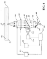
- the invention might be used in an optical device as shown in Fig.4 .
- Such a device is intended for scanning a multilayer information carrier 400.
- the multilayer information carrier 400 has two layers 401 and 402.
- the optical device can scan one layer or the other, by changing the axial position of the objective lens 208, thanks to the servo controller 213.
- the amounts of information carrier material traversed by the first radiation beam 203 are different when the first radiation beam 203 is focussed on the information layer 401 or on the information layer 402
- the spherical aberration introduced in the first radiation beam 203 by the information carrier changes from one information layer to another.
- a spherical-aberration compensator 403 which is placed between the collimator lens 206 and the objective lens 208.
- the spherical-aberration compensator imparts a phase shift to the wavefront of the first radiation beam 203, which phase shift depends on the position in the wavefront.
- the spherical aberration is first measured, as described in the description of Fig.2 . Then a signal corresponding to the spherical aberration is sent to a servo controller 404, which commands properties of the phase shift imparted by the spherical-aberration compensator 403, depending on the amount of spherical aberration.
- the spherical-aberration compensator 403 might be a deformable folding mirror or a liquid crystal cell.
Landscapes
- Physics & Mathematics (AREA)
- Optics & Photonics (AREA)
- General Physics & Mathematics (AREA)
- Chemical & Material Sciences (AREA)
- Crystallography & Structural Chemistry (AREA)
- Optical Head (AREA)
- Optical Recording Or Reproduction (AREA)
- Testing Of Optical Devices Or Fibers (AREA)
- Prostheses (AREA)
- Eye Examination Apparatus (AREA)
Abstract
Description
- The present invention relates to an optical device comprising means for detecting a spherical aberration.
- The present invention also relates to a method for detecting a spherical aberration.
- The present invention is particularly relevant for an optical disc apparatus for reading and/or recording data from and/or to an optical disc, e.g. a CD, a DVD or a Blu-Ray Disc (BD) player and/or recorder.
- An optical device comprising means for detecting a spherical aberration is known from Applicant's
US 6,229,600 . The invention described in this patent aims at providing a detection system for detecting a spherical aberration. Such a detection system is used in an optical device comprising means for focussing a radiation beam on an information carrier. Information carriers are often scanned through a transparent layer protecting an information layer. A small variation of the thickness of the transparent layer causes a substantial change in the spherical aberration incurred by a high-numerical aperture radiation beam traversing the transparent layer. This spherical aberration might be reduced, by using, for example, a dual lens objective, as described inUS 6,229,600 . But the amount of spherical aberration might be determined in order to be able to reduce the spherical aberration. -
Fig.1 illustrates how the spherical aberration is detected in an optical device, according toUS 6,229,600 . The optical device comprises aradiation source 101 controlled by adriver 113, acollimator lens 102, anobjective lens 103, a plano-convex lens 104, a beam-splitter 105, twodetectors signal processor 108, anadder 109, anamplifier 110, and twoservo controllers information carrier 100. - The
radiation source 101 produces a radiation beam, which is focussed on an information layer of theinformation carrier 100 thanks to thecollimator lens 102 and theobjective lens 103. The radiation beam is reflected by the information layer and is transformed to a converging radiation beam by theobjective lens 103 and thecollimator lens 102. Part of this converging radiation beam incident on a central zone of thebeam splitter 105 is deflected towardsdetector 106 and part of this converging radiation beam incident on an outer zone of thebeam splitter 105 is deflected towardsdetector 107. The signal detected bydetectors signal processor 108 to provide focus error signals corresponding to the inner part and the outer part of the reflected radiation beam. - The
signal processor 108 also determines the spherical aberration of the radiation beam by subtracting these two focus error signals. - Knowing the focus error signals, the servo controller111 drives an actuator controlling the axial position of the
objective lens 103 in order to correct the focus error. Knowing the spherical aberration, theservo controller 112 drives an actuator controlling the axial position of the plano-convex lens 104 in order to correct the spherical aberration. - A disadvantage of the optical device described above lies in the fact that it requires a
special beam splitter 105, which makes the optical device bulky and complicated. Another disadvantage lies in the fact that it requires two detectors, which make the optical device bulky and complicated, as these two detectors require a different readout channel, comprising different associated electronics. -
EP 1215667 A2 discloses an optical head for use in an optical data recording/reproducing apparatus. Light issued from a semiconductor laser is split into a main beam that is zeroth order light and subbeams that are positive and negative first-order diffracted light. A focus error signal is detected from each of the main beam and subbeams. A diffraction optical element causes the main beam and subbeams to differ in light intensity distribution from each other when incident to an object lens. As a result, when a disk or optical recording medium has a thickness error, the focus error signal derived from the main beam and focus error signals derived from the subbeams differ in zero-crossing point from each other. The thickness error is detected on the basis of the difference between the zero-crossing points. - It is an object of the invention to provide an optical device comprising simplified means for detecting a spherical aberration.
- To this end, the invention proposes an optical device comprising means for focussing a first radiation beam having a first numerical aperture and a second radiation beam having a second numerical aperture different from the first numerical aperture, on an information carrier, means for switchip between the first radiation beam and the second radiation (beam) means for detecting a first focus error signal corresponding to the first radiation beam and a second focus error signal corresponding to the second radiation beam, and means for measuring a spherical aberration of the first radiation beam from the first and second focus error signals, wherein said means for focussing said first and second radiation beam are adapted for non-simultaneously focussing said first radiation beam and said second radiation beam on said information carrier.
- The invention is based on the recognition that, in a radiation beam having spherical aberration, the rays in the centre of the beam and the rays at the periphery of the beam have different focal points, when focussed on an information carrier. The difference between the positions of the focal points provides a measure of the spherical aberration. Now, the rays in the centre of the beam have a numerical aperture which is lower than the numerical aperture of the rays at the periphery of the beam. As a consequence, a measurement of the spherical aberration can be obtained by detecting the difference in the positions of the focal points of two radiation beams having different numerical apertures, these two radiation beams being focussed on the information carrier. Thus, no beam-splitter is needed in such an optical device, which simplifies the device.
- In a preferred embodiment, the first and second radiation beams are produced by two radiation sources, the device further comprises means for switching on and off the radiation beams, and the first and second focus error signals are detected by a same detector. According to this embodiment, two radiation sources are used in order to produce the two radiation beams having different numerical apertures. One of the radiation beams, for example a blue laser, is used to scan an information layer, for example a Blu-ray disc, the other radiation beam, which is for example intended to scan a DVD, is used to provide a measurement of the spherical aberration. For example, before scanning a disc, the first radiation beam is switched off and the second radiation beam is switched on, a measurement of the focus error signal of the second radiation beam and then of the spherical aberration is performed, after which the second radiation beam is switched off and the first radiation beam is switched on in order to scan the information layer. As the two radiation beams are switched on separately in time, a same detector is used to detect the focus error signals corresponding to the two radiation beams. As a consequence, the optical device is simplified.
- Advantageously, the optical device further comprises means for pulsing the second radiation beam and means for detecting a pulsed focus error signal corresponding to said pulsed second radiation beam. This allows increasing the signal to noise ratio, and thus leads to a more accurate measurement of the spherical aberration.
- In an advantageous embodiment, the first and second radiation beams are produced by a same radiation source, the optical device further comprises means for reducing the numerical aperture of the first radiation beam in order to obtain the second radiation beam, and means for switching on and off said reducing means.
- According to this embodiment, the second radiation beam, which is used for measuring the spherical aberration, is part of the first radiation beam. This embodiment is advantageously used in optical devices, where only one radiation source is available.
- Advantageously, a liquid crystal cell is placed between the radiation source and the focussing means in order to reduce the numerical aperture of the first radiation beam. Such a liquid crystal cell is easily and rapidly switchable, thanks to electric fields. As a consequence, constructing the second radiation beam from the first radiation beam is easy. Moreover, the liquid crystal cell can be switched on and off in a pulsed way, which leads to a pulsed second radiation beam, thus improving the signal to noise ratio.
- The invention also relates to a method for detecting a spherical aberration, said method comprising the steps of:
- focussing a first radiation beam having a first numerical aperture
on an information carrier; - detecting a first focus error signal corresponding to the first radiation beam;
- witching to and focusing a second radiation beam having a second numerical aperture different from the first numerical aperture.
- detecting a second focus error signal corresponding to the second radiation beam; and
- measuring a spherical aberration of the first radiation beam from the first and second focus error signals
- Advantageously, the step of measuring a spherical aberration of the first radiation beam from the first and second focus error signals is performed by calculating the difference between the first focus error signal and the second focus error signal, and subtracting a predefined focus error signal from said difference, said predefined focus errorsignal corresponding to a focus error signal obtained with the second radiation beam focussed on an information carrier having a predetermined thickness.
- In order to obtain an accurate measurement of the spherical aberration due to the variation of the cover layer thickness of the information carrier, a predefined focus error signal is taken into account, which corresponds to a focus error signal obtained with the second radiation beam focussed on an information carrier having a predetermined thickness. Actually, even with an information carrier having a predefined perfect cover layer thickness, the second radiation beam has a focus error, because the information carrier is intended to be read by the first radiation beam. This predefined focus error signal might be determined during a manufacturing process, and loaded in a memory of the optical device, in order to be subtracted from the difference between the first focus error signal and the second focus error signal.
- These and other aspects of the invention will be apparent from and elucidated with reference to the embodiments described hereinafter.
- The invention will now be described in more detail, by way of example, with reference to the accompanying drawings, in which:
-
Fig. 1 shows an optical device in accordance with the background art; -
Fig. 2 shows an optical device in accordance with a preferred embodiment of the invention; -
Fig. 3 shows an optical device in accordance with an advantageous embodiment of the invention; -
Fig. 4 shows an optical device in accordance with another embodiment of the invention. - An optical device according to a preferred embodiment of the invention is depicted in
Fig.2 . Such an optical device comprises afirst radiation source 201 for producing afirst radiation beam 203, asecond radiation source 202 for producing asecond radiation beam 204, afirst beam splitter 205, acollimator lens 206, asecond beam splitter 207, anobjective lens 208, a plano-convex lens 209, aservo lens 210, detecting means 211, measuring means 212 and twoservo controllers information carrier 200. - In the example described hereinafter, the
information carrier 200 is a Blu-ray disc comprising an information layer. During a scanning operation, this Blu-ray disc is scanned by thefirst radiation beam 203 produced by thefirst radiation source 201. Thefirst radiation beam 203 has a first wavelength equal to 405 nanometres. Thecollimator lens 206 and theobjective lens 208 focus thefirst radiation beam 203 on the information layer of theinformation carrier 200. Thecollimator lens 206 and theobjective lens 208 are focussing means. The numerical aperture of the first radiation beam is 0.85. During a scanning operation, a first focus error signal might be detected, corresponding to thefirst radiation beam 203. This first focus error signal might be used to correct the axial position of theobjective lens 208 in order to compensate for a focus error signal of thefirst radiation beam 203. A signal is sent to theservo controller 213, which drives an actuator in order to move theobjective lens 208 axially. - The first focus error signal is detected by the detecting
means 211. Thefirst radiation beam 203, reflected by theinformation carrier 200, is transformed to a parallel beam by theobjective lens 208, and then reaches theservo lens 210, thanks to thesecond beam splitter 207. This reflected beam then reaches the detecting means 211, which detects a first focus error signal, based on any focus detection method known in the art. For example, the astigmatic focus detection method or the Foucault detection method might be used. These focus detection methods are described, for example, inUS 6,229,600 . It should be noted that the detecting means 211 are preferably placed in the optical device by using afirst radiation beam 203 without spherical aberration. In order to place the detecting means, a `perfect' disc having a calibrated cover layer thickness of 100 micrometers is used. - How the spherical aberration caused by a variation of the cover layer thickness compared to the calibrated cover layer thickness is measured, is described hereinafter. Such a measurement might be performed when a new disc is introduced in the optical device. The
first radiation beam 203 is switched off, for example by switching off thefirst radiation source 201. Thesecond radiation beam 204 is then switched on. Thissecond radiation beam 204 is sent to thecollimator lens 206, thanks to thefirst beam splitter 205. Thesecond radiation beam 204 is then transformed to a parallel beam by thecollimator lens 206 and focussed on theinformation carrier 200, thanks to theobjective lens 208. The numerical aperture of thissecond radiation beam 204 is 0.65 and the wavelength of thesecond radiation beam 204 is 650 nanometres. Thissecond radiation beam 204 is usually used for scanning a DVD. - The
second radiation beam 204, reflected by theinformation carrier 200, is transformed to a parallel beam by theobjective lens 208 and then reaches theservo lens 210, thanks to thesecond beam splitter 207. This reflected beam then reaches the detecting means 211, which detects a second focus error signal, as described above for thefirst radiation beam 203. - Then, the measuring means 212 performs a difference between the first focus error signal and the second focus error signal. This difference is a measurement of the spherical aberration of the
first radiation beam 203, due to the variation in the cover layer thickness. Actually, as explained inUS 6,229,600 , the spherical aberration of a radiation beam might be measured by computing the difference between the focus error signal corresponding to a peripheral part of the radiation beam and the focus error signal corresponding to an inner part of the radiation beam. In this invention, thesecond radiation beam 204, which has a lower numerical aperture than thefirst radiation beam 203, plays the role of the inner part of thefirst radiation beam 203. As a consequence, performing a difference between the first focus error signal and the second focus error signal allows measuring the spherical aberration of thefirst radiation beam 203. - It should be noted that the measurement of the second focus error signal and the first focus error signal are preferably performed at short intervals. Actually, it is possible that the focus error signal of a given radiation beam is different from one place of a disc to another place, due to defaults of the disc. As the disc rotates when the focus error signals are detected, it is preferable to measure the focus error signals of the first and second radiation beams 203 and 204 when the disc is substantially at the same place, so that the measurement of the spherical aberration is not affected by defaults of the disc.
- It should also be noted that a more accurate measurement of the spherical aberration of the
first radiation beam 203 might be performed. Actually, when thesecond radiation beam 204 is focussed on a 'perfect' information carrier having a calibrated cover layer thickness, thissecond radiation beam 204 has a focus error, because the optical device is optimised for the wavelength of thefirst radiation beam 203, which differs from the wavelength of thesecond radiation beam 204. As a consequence, a predefined focus error signal might be detected during a manufacturing process, corresponding to thesecond radiation beam 204 focussed on an information carrier having a calibrated cover layer thickness. This predefined focus error signal might be stored in a memory of the measuring means 212. Then, in order to obtain an accurate measurement of the spherical aberration of thefirst radiation beam 203, this predefined focus error signal is subtracted from the difference between the first focus error signal and the second focus error signal. - Advantageously, the
second radiation beam 204 is pulsed. This might be achieved by pulsing thesecond radiation source 202. Thesecond radiation beam 204 is pulsed at a known pulsing frequency. As a consequence, the second focus error signal is a pulsed signal having a known frequency. This pulsed signal is then detected by the detecting means 211, which comprise means for detecting a signal at the pulsing frequency. For example, a synchronous detection might be performed in order to obtain the second focus error signal. This allows increasing the signal to noise ratio, which leads to a more accurate-measurement of the spherical aberration of thefirst radiation beam 203. - It should be noted that the means for switching on and off the two radiation beams are not limited to what has been described hereinbefore, that is to say switching on and off the two radiation sources. For example, a filter might be used before the detecting
means 211. This filter is able to select one of the two radiation beams, based on the wavelengths of these radiation beams. Then, in order to measure the spherical aberration, the filter is activated in such a way that it transmits thesecond radiation beam 204 and stops thefirst radiation beam 203. - The measurement of the spherical aberration is then used in order to correct the spherical aberration of the
first radiation beam 203. This spherical aberration, which arises when thefirst radiation beam 203 is focussed through a cover layer, the thickness of which is different from the design thickness of this layer, is compensated by changing the axial position of the plano-convex lens 209. The measuring means sends a signal to theservo controller 214, which signal corresponds to the spherical aberration. Theservo controller 214 then drives an actuator, in order to change the position of the plano-convex lens 209. This change causes the plano-convex lens 209 to produce, due to the changing magnification, an amount of spherical aberration which compensates the spherical aberration produced by the variation in the cover layer thickness. - It should be noted that other means for compensating the spherical aberration might be used. For example, by shifting the position of the
collimator lens 206, the conjugate of thefirst radiation beam 203 is varied, inducing spherical aberration in theobjective lens 208, which can be used for compensating for spherical aberration due to variations in cover layer thickness. This is detailed in "Optical Pick-Up for blue optical recording at NA=0.85", written by B.H.W. Hendriks et al., published in the Optical Review volume 8, . - An optical device according to an advantageous embodiment of the invention is depicted in
Fig.3 . According to this embodiment, thesecond radiation beam 204 is produced from thefirst radiation beam 203, thanks to aliquid crystal cell 300. Thefirst radiation beam 203 and thesecond radiation beam 204 are thus produced from thesame radiation source 201. This means that the first and second radiation-beams - The
second radiation beam 204 is obtained from thefirst radiation beam 203 by applying a voltage to theliquid crystal cell 300, which is placed between thecollimator lens 206 and theobjective lens 208. When no voltage is applied to theliquid crystal cell 300, the whole beam incident on theliquid crystal cell 300 is transmitted. When a voltage is applied to theliquid crystal cell 300, only an inner part of the beam incident on theliquid crystal cell 300 is transmitted. This means that the liquid crystal cell allows for reducing the numerical aperture of thefirst radiation beam 203. - As a consequence, when a scanning operation is performed, in which the information carrier has to be scanned by the
first radiation beam 203, no voltage is applied to theliquid crystal cell 300. This is the same when the first focus error signal corresponding to thefirst radiation beam 203 is detected. When the spherical aberration has to be measured, for example when a new disc is inserted inside the optical device, a voltage is applied to theliquid crystal cell 300, and the second focus error signal is thus detected. - It should be noted that the
second radiation beam 204 might be pulsed by applying an alternative voltage to theliquid crystal cell 300. In this case, the pulsing frequency is the frequency of the alternative voltage. As described above, this allows increasing the signal to noise ratio. - The description above illustrates rather than limits the invention. Actually, the invention is not limited to the optical devices as shown in
Figs.2 and3 . Other optical devices might be based on the invention, in which two radiation beams having different numerical apertures are used in order to obtain a measurement of the spherical aberration. For example, the invention might be used in an optical device as shown inFig.4 . - Such a device is intended for scanning a
multilayer information carrier 400. In this example, themultilayer information carrier 400 has twolayers objective lens 208, thanks to theservo controller 213. But the amounts of information carrier material traversed by thefirst radiation beam 203 are different when thefirst radiation beam 203 is focussed on theinformation layer 401 or on theinformation layer 402 As a consequence, the spherical aberration introduced in thefirst radiation beam 203 by the information carrier changes from one information layer to another. These changes are compensated by a spherical-aberration compensator 403, which is placed between thecollimator lens 206 and theobjective lens 208. The spherical-aberration compensator imparts a phase shift to the wavefront of thefirst radiation beam 203, which phase shift depends on the position in the wavefront. - The spherical aberration is first measured, as described in the description of
Fig.2 . Then a signal corresponding to the spherical aberration is sent to aservo controller 404, which commands properties of the phase shift imparted by the spherical-aberration compensator 403, depending on the amount of spherical aberration. The spherical-aberration compensator 403 might be a deformable folding mirror or a liquid crystal cell. - Any reference sign in the following claims should not be construed as limiting the claim. It will be obvious that the use of the verb "to comprise" and its conjugations does not exclude the presence of elements other than those defined in any claim. The word "a" or "an" preceding an element does not exclude the presence of a plurality of such elements.
Claims (7)
- An optical device comprising:- means (206, 208) for focussing a first radiation beam (203) having a first numerical aperture and a second radiation beam (204) having a second numerical aperture different from the first numerical aperture, on an information carrier (200); means for switching between the first radiation beam and the second radiation beam- means (211) for detecting a first focus error signal corresponding to the first radiation beam and a second focus error signal corresponding to the second radiation beam; and- means (212) for measuring a spherical aberration of the first radiation beam from the first and second focus error signals,characterized in that said means (206, 208) for focussing said first and second radiation beam are adapted for non-simultaneously focussing said first radiation beam (203) and said second radiation beam (204) on said information carrier (200).
- An optical device as claimed in claim 1, wherein the first and second radiation beams are produced by two radiation sources (201, 202), , the first and second focus error signals being detected by a same detector.
- An optical device as claimed in claim 2, further comprising means for pulsing the second radiation beam and means for detecting a pulsed focus error signal corresponding to said pulsed second radiation beam.
- An optical device as claimed in claim 1, wherein the first and second radiation beams are produced by a same radiation source, the optical device further comprising means (300) for reducing the numerical aperture of the first radiation beam in order to obtain the second radiation beam, and means for switching on and off said reducing means.
- An optical device as claimed in claim 4, wherein a liquid crystal cell is placed between the radiation source and the focussing means in order to reduce the numerical aperture of the first radiation beam.
- A method for detecting a spherical aberration, said method comprising the steps of:- focussing a first radiation beam having a first numerical aperture on an information carrier;- detecting a first focus error signal corresponding to the first radiation beam; switching to and focussing a second radiation beam having a second numerical aperture different from the first numerical aperture on the information carrier;- detecting a second focus error signal corresponding to the second radiation beam; and- measuring a spherical aberration of the first radiation beam from the first and second focus error signals
- A method as claimed in claim 6, the step of measuring a spherical aberration of the first radiation beam from the first and second focus error signals being performed by:- calculating the difference between the first focus error signal and the second focus error signal,- subtracting a predefined focus error signal from said difference, said predefined focus error signal corresponding to a focus error signal obtained with the second radiation beam focussed on an information carrier having a predetermined thickness.
Priority Applications (1)
| Application Number | Priority Date | Filing Date | Title |
|---|---|---|---|
| EP03809394A EP1556858B1 (en) | 2002-10-23 | 2003-10-01 | Spherical aberration detection |
Applications Claiming Priority (4)
| Application Number | Priority Date | Filing Date | Title |
|---|---|---|---|
| EP02292625 | 2002-10-23 | ||
| EP02292625 | 2002-10-23 | ||
| PCT/IB2003/004355 WO2004038707A1 (en) | 2002-10-23 | 2003-10-01 | Spherical aberration detection |
| EP03809394A EP1556858B1 (en) | 2002-10-23 | 2003-10-01 | Spherical aberration detection |
Publications (2)
| Publication Number | Publication Date |
|---|---|
| EP1556858A1 EP1556858A1 (en) | 2005-07-27 |
| EP1556858B1 true EP1556858B1 (en) | 2011-07-13 |
Family
ID=32116331
Family Applications (1)
| Application Number | Title | Priority Date | Filing Date |
|---|---|---|---|
| EP03809394A Expired - Lifetime EP1556858B1 (en) | 2002-10-23 | 2003-10-01 | Spherical aberration detection |
Country Status (8)
| Country | Link |
|---|---|
| US (1) | US7292324B2 (en) |
| EP (1) | EP1556858B1 (en) |
| JP (1) | JP4376786B2 (en) |
| KR (1) | KR100935588B1 (en) |
| CN (1) | CN1331131C (en) |
| AT (1) | ATE516581T1 (en) |
| AU (1) | AU2003265077A1 (en) |
| WO (1) | WO2004038707A1 (en) |
Families Citing this family (3)
| Publication number | Priority date | Publication date | Assignee | Title |
|---|---|---|---|---|
| JP4042682B2 (en) * | 2003-11-10 | 2008-02-06 | 船井電機株式会社 | Optical head device |
| US7859967B2 (en) * | 2007-08-30 | 2010-12-28 | Lite-On It Corporation | Optical disk drive with spherical aberration measurement and method of measuring spherical aberration in an optical disk drive |
| CN102661853B (en) * | 2012-05-08 | 2014-03-26 | 北京理工大学 | Method for measuring spherical aberration of confocal system |
Citations (1)
| Publication number | Priority date | Publication date | Assignee | Title |
|---|---|---|---|---|
| EP1215667A2 (en) * | 2000-12-18 | 2002-06-19 | Nec Corporation | Optical head and optical data recording/reproducing apparatus using the same |
Family Cites Families (8)
| Publication number | Priority date | Publication date | Assignee | Title |
|---|---|---|---|---|
| US5281797A (en) * | 1991-12-26 | 1994-01-25 | Hitachi, Ltd. | Short wavelength optical disk head having a changeable aperture |
| KR100209918B1 (en) * | 1997-03-28 | 1999-07-15 | 윤종용 | Optical pickup for cd-r and dvd using hologram ring lens |
| WO1999018466A1 (en) * | 1997-10-06 | 1999-04-15 | Koninklijke Philips Electronics N.V. | Spherical-aberration detection system and optical device using the same |
| JP3574747B2 (en) * | 1998-08-05 | 2004-10-06 | パイオニア株式会社 | Optical pickup, information reproducing device and information recording device |
| JP2000076665A (en) * | 1998-08-27 | 2000-03-14 | Pioneer Electronic Corp | Optical pickup device |
| JP2000182254A (en) * | 1998-12-15 | 2000-06-30 | Pioneer Electronic Corp | Pickup device |
| KR100694029B1 (en) * | 2000-03-04 | 2007-03-12 | 삼성전자주식회사 | Compatible optical pickup capable of high density record/reproduction |
| JP2001307349A (en) * | 2000-04-19 | 2001-11-02 | Hitachi Ltd | Optical disk device |
-
2003
- 2003-10-01 EP EP03809394A patent/EP1556858B1/en not_active Expired - Lifetime
- 2003-10-01 JP JP2004546236A patent/JP4376786B2/en not_active Expired - Lifetime
- 2003-10-01 US US10/531,937 patent/US7292324B2/en not_active Expired - Fee Related
- 2003-10-01 AT AT03809394T patent/ATE516581T1/en not_active IP Right Cessation
- 2003-10-01 AU AU2003265077A patent/AU2003265077A1/en not_active Abandoned
- 2003-10-01 KR KR1020057006803A patent/KR100935588B1/en not_active IP Right Cessation
- 2003-10-01 WO PCT/IB2003/004355 patent/WO2004038707A1/en active Application Filing
- 2003-10-01 CN CNB2003801018869A patent/CN1331131C/en not_active Expired - Fee Related
Patent Citations (1)
| Publication number | Priority date | Publication date | Assignee | Title |
|---|---|---|---|---|
| EP1215667A2 (en) * | 2000-12-18 | 2002-06-19 | Nec Corporation | Optical head and optical data recording/reproducing apparatus using the same |
Also Published As
| Publication number | Publication date |
|---|---|
| JP2006504214A (en) | 2006-02-02 |
| JP4376786B2 (en) | 2009-12-02 |
| CN1331131C (en) | 2007-08-08 |
| ATE516581T1 (en) | 2011-07-15 |
| WO2004038707A1 (en) | 2004-05-06 |
| AU2003265077A1 (en) | 2004-05-13 |
| CN1705989A (en) | 2005-12-07 |
| US20060083510A1 (en) | 2006-04-20 |
| KR20050055026A (en) | 2005-06-10 |
| KR100935588B1 (en) | 2010-01-07 |
| EP1556858A1 (en) | 2005-07-27 |
| US7292324B2 (en) | 2007-11-06 |
Similar Documents
| Publication | Publication Date | Title |
|---|---|---|
| US7746736B2 (en) | Optical head and optical disk device capable of detecting spherical aberration | |
| US20120106313A1 (en) | Optical Disk Device and Optical Disk Discriminating Method | |
| JP2000171346A (en) | Aberration detecting device and optical pickup device | |
| JP2003045042A (en) | Thickness irregularity correction method for information recording medium and information recording and reproducing device using thickness irregularity correction method | |
| JPH10134400A (en) | Optical head | |
| EP1661128B1 (en) | Optical scanning device | |
| EP1556858B1 (en) | Spherical aberration detection | |
| US20080212418A1 (en) | Optical disc device | |
| US7630278B2 (en) | Focusing control method for reading/writing optical disc | |
| JP2002170256A (en) | Optical head device, recording and/or reproducing device and recording and/or reproducing method | |
| EP2058806A1 (en) | Optical disc apparatus and spherical aberration correcting method | |
| US8000187B2 (en) | Optical disc device | |
| US7310297B2 (en) | Optical disk device | |
| EP2017837A2 (en) | Optical pickup device | |
| US20080316891A1 (en) | Optical Scanning Device | |
| US20080175107A1 (en) | Focusing control method for reading/writing optical disc | |
| KR101000772B1 (en) | Optical disk apparatus | |
| JP2009537054A (en) | Optical scanning device | |
| JP2006031749A (en) | Optical pickup device and optical disk drive | |
| EP1581940B1 (en) | Apparatus for reading from and/or writing to optical recording media | |
| JP2002055024A (en) | Aberration detecting method and optical pickup device | |
| JP2004133999A (en) | Focal error detection device and optical pickup device | |
| JP2007334948A (en) | Position adjusting method of photodetector, and optical disk drive | |
| US20070097810A1 (en) | Optical head unit and optical disc apparatus | |
| JP2002039914A (en) | Method and apparatus for detecting aberration, and optical pickup device |
Legal Events
| Date | Code | Title | Description |
|---|---|---|---|
| PUAI | Public reference made under article 153(3) epc to a published international application that has entered the european phase |
Free format text: ORIGINAL CODE: 0009012 |
|
| 17P | Request for examination filed |
Effective date: 20050523 |
|
| AK | Designated contracting states |
Kind code of ref document: A1 Designated state(s): AT BE BG CH CY CZ DE DK EE ES FI FR GB GR HU IE IT LI LU MC NL PT RO SE SI SK TR |
|
| AX | Request for extension of the european patent |
Extension state: AL LT LV MK |
|
| DAX | Request for extension of the european patent (deleted) | ||
| 17Q | First examination report despatched |
Effective date: 20071113 |
|
| GRAP | Despatch of communication of intention to grant a patent |
Free format text: ORIGINAL CODE: EPIDOSNIGR1 |
|
| GRAS | Grant fee paid |
Free format text: ORIGINAL CODE: EPIDOSNIGR3 |
|
| GRAA | (expected) grant |
Free format text: ORIGINAL CODE: 0009210 |
|
| AK | Designated contracting states |
Kind code of ref document: B1 Designated state(s): AT BE BG CH CY CZ DE DK EE ES FI FR GB GR HU IE IT LI LU MC NL PT RO SE SI SK TR |
|
| REG | Reference to a national code |
Ref country code: GB Ref legal event code: FG4D |
|
| REG | Reference to a national code |
Ref country code: CH Ref legal event code: EP |
|
| REG | Reference to a national code |
Ref country code: IE Ref legal event code: FG4D |
|
| REG | Reference to a national code |
Ref country code: DE Ref legal event code: R096 Ref document number: 60337702 Country of ref document: DE Effective date: 20110901 |
|
| REG | Reference to a national code |
Ref country code: DE Ref legal event code: R084 Ref document number: 60337702 Country of ref document: DE |
|
| REG | Reference to a national code |
Ref country code: DE Ref legal event code: R084 Ref document number: 60337702 Country of ref document: DE Effective date: 20110820 |
|
| REG | Reference to a national code |
Ref country code: NL Ref legal event code: VDEP Effective date: 20110713 |
|
| REG | Reference to a national code |
Ref country code: AT Ref legal event code: MK05 Ref document number: 516581 Country of ref document: AT Kind code of ref document: T Effective date: 20110713 |
|
| PG25 | Lapsed in a contracting state [announced via postgrant information from national office to epo] |
Ref country code: NL Free format text: LAPSE BECAUSE OF FAILURE TO SUBMIT A TRANSLATION OF THE DESCRIPTION OR TO PAY THE FEE WITHIN THE PRESCRIBED TIME-LIMIT Effective date: 20110713 Ref country code: PT Free format text: LAPSE BECAUSE OF FAILURE TO SUBMIT A TRANSLATION OF THE DESCRIPTION OR TO PAY THE FEE WITHIN THE PRESCRIBED TIME-LIMIT Effective date: 20111114 Ref country code: SE Free format text: LAPSE BECAUSE OF FAILURE TO SUBMIT A TRANSLATION OF THE DESCRIPTION OR TO PAY THE FEE WITHIN THE PRESCRIBED TIME-LIMIT Effective date: 20110713 Ref country code: BE Free format text: LAPSE BECAUSE OF FAILURE TO SUBMIT A TRANSLATION OF THE DESCRIPTION OR TO PAY THE FEE WITHIN THE PRESCRIBED TIME-LIMIT Effective date: 20110713 Ref country code: FI Free format text: LAPSE BECAUSE OF FAILURE TO SUBMIT A TRANSLATION OF THE DESCRIPTION OR TO PAY THE FEE WITHIN THE PRESCRIBED TIME-LIMIT Effective date: 20110713 |
|
| PGFP | Annual fee paid to national office [announced via postgrant information from national office to epo] |
Ref country code: FR Payment date: 20111115 Year of fee payment: 9 |
|
| PG25 | Lapsed in a contracting state [announced via postgrant information from national office to epo] |
Ref country code: GR Free format text: LAPSE BECAUSE OF FAILURE TO SUBMIT A TRANSLATION OF THE DESCRIPTION OR TO PAY THE FEE WITHIN THE PRESCRIBED TIME-LIMIT Effective date: 20111014 Ref country code: CY Free format text: LAPSE BECAUSE OF FAILURE TO SUBMIT A TRANSLATION OF THE DESCRIPTION OR TO PAY THE FEE WITHIN THE PRESCRIBED TIME-LIMIT Effective date: 20110713 Ref country code: AT Free format text: LAPSE BECAUSE OF FAILURE TO SUBMIT A TRANSLATION OF THE DESCRIPTION OR TO PAY THE FEE WITHIN THE PRESCRIBED TIME-LIMIT Effective date: 20110713 Ref country code: SI Free format text: LAPSE BECAUSE OF FAILURE TO SUBMIT A TRANSLATION OF THE DESCRIPTION OR TO PAY THE FEE WITHIN THE PRESCRIBED TIME-LIMIT Effective date: 20110713 |
|
| PG25 | Lapsed in a contracting state [announced via postgrant information from national office to epo] |
Ref country code: SK Free format text: LAPSE BECAUSE OF FAILURE TO SUBMIT A TRANSLATION OF THE DESCRIPTION OR TO PAY THE FEE WITHIN THE PRESCRIBED TIME-LIMIT Effective date: 20110713 Ref country code: CZ Free format text: LAPSE BECAUSE OF FAILURE TO SUBMIT A TRANSLATION OF THE DESCRIPTION OR TO PAY THE FEE WITHIN THE PRESCRIBED TIME-LIMIT Effective date: 20110713 |
|
| PLBE | No opposition filed within time limit |
Free format text: ORIGINAL CODE: 0009261 |
|
| STAA | Information on the status of an ep patent application or granted ep patent |
Free format text: STATUS: NO OPPOSITION FILED WITHIN TIME LIMIT |
|
| PG25 | Lapsed in a contracting state [announced via postgrant information from national office to epo] |
Ref country code: EE Free format text: LAPSE BECAUSE OF FAILURE TO SUBMIT A TRANSLATION OF THE DESCRIPTION OR TO PAY THE FEE WITHIN THE PRESCRIBED TIME-LIMIT Effective date: 20110713 Ref country code: MC Free format text: LAPSE BECAUSE OF NON-PAYMENT OF DUE FEES Effective date: 20111031 Ref country code: IT Free format text: LAPSE BECAUSE OF FAILURE TO SUBMIT A TRANSLATION OF THE DESCRIPTION OR TO PAY THE FEE WITHIN THE PRESCRIBED TIME-LIMIT Effective date: 20110713 Ref country code: RO Free format text: LAPSE BECAUSE OF FAILURE TO SUBMIT A TRANSLATION OF THE DESCRIPTION OR TO PAY THE FEE WITHIN THE PRESCRIBED TIME-LIMIT Effective date: 20110713 |
|
| REG | Reference to a national code |
Ref country code: CH Ref legal event code: PL |
|
| 26N | No opposition filed |
Effective date: 20120416 |
|
| PG25 | Lapsed in a contracting state [announced via postgrant information from national office to epo] |
Ref country code: DK Free format text: LAPSE BECAUSE OF FAILURE TO SUBMIT A TRANSLATION OF THE DESCRIPTION OR TO PAY THE FEE WITHIN THE PRESCRIBED TIME-LIMIT Effective date: 20110713 |
|
| PG25 | Lapsed in a contracting state [announced via postgrant information from national office to epo] |
Ref country code: DE Free format text: LAPSE BECAUSE OF NON-PAYMENT OF DUE FEES Effective date: 20120501 Ref country code: LI Free format text: LAPSE BECAUSE OF NON-PAYMENT OF DUE FEES Effective date: 20111031 Ref country code: CH Free format text: LAPSE BECAUSE OF NON-PAYMENT OF DUE FEES Effective date: 20111031 |
|
| REG | Reference to a national code |
Ref country code: IE Ref legal event code: MM4A |
|
| REG | Reference to a national code |
Ref country code: DE Ref legal event code: R097 Ref document number: 60337702 Country of ref document: DE Effective date: 20120416 |
|
| REG | Reference to a national code |
Ref country code: DE Ref legal event code: R119 Ref document number: 60337702 Country of ref document: DE Effective date: 20120501 |
|
| PG25 | Lapsed in a contracting state [announced via postgrant information from national office to epo] |
Ref country code: IE Free format text: LAPSE BECAUSE OF NON-PAYMENT OF DUE FEES Effective date: 20111001 |
|
| PG25 | Lapsed in a contracting state [announced via postgrant information from national office to epo] |
Ref country code: ES Free format text: LAPSE BECAUSE OF FAILURE TO SUBMIT A TRANSLATION OF THE DESCRIPTION OR TO PAY THE FEE WITHIN THE PRESCRIBED TIME-LIMIT Effective date: 20111024 |
|
| PG25 | Lapsed in a contracting state [announced via postgrant information from national office to epo] |
Ref country code: LU Free format text: LAPSE BECAUSE OF NON-PAYMENT OF DUE FEES Effective date: 20111001 |
|
| GBPC | Gb: european patent ceased through non-payment of renewal fee |
Effective date: 20121001 |
|
| PG25 | Lapsed in a contracting state [announced via postgrant information from national office to epo] |
Ref country code: BG Free format text: LAPSE BECAUSE OF FAILURE TO SUBMIT A TRANSLATION OF THE DESCRIPTION OR TO PAY THE FEE WITHIN THE PRESCRIBED TIME-LIMIT Effective date: 20111013 |
|
| REG | Reference to a national code |
Ref country code: FR Ref legal event code: ST Effective date: 20130628 |
|
| PG25 | Lapsed in a contracting state [announced via postgrant information from national office to epo] |
Ref country code: GB Free format text: LAPSE BECAUSE OF NON-PAYMENT OF DUE FEES Effective date: 20121001 |
|
| PG25 | Lapsed in a contracting state [announced via postgrant information from national office to epo] |
Ref country code: FR Free format text: LAPSE BECAUSE OF NON-PAYMENT OF DUE FEES Effective date: 20121031 |
|
| PG25 | Lapsed in a contracting state [announced via postgrant information from national office to epo] |
Ref country code: TR Free format text: LAPSE BECAUSE OF FAILURE TO SUBMIT A TRANSLATION OF THE DESCRIPTION OR TO PAY THE FEE WITHIN THE PRESCRIBED TIME-LIMIT Effective date: 20110713 |
|
| PG25 | Lapsed in a contracting state [announced via postgrant information from national office to epo] |
Ref country code: HU Free format text: LAPSE BECAUSE OF FAILURE TO SUBMIT A TRANSLATION OF THE DESCRIPTION OR TO PAY THE FEE WITHIN THE PRESCRIBED TIME-LIMIT Effective date: 20110713 |