EP1556645B1 - Raccord de tuyauterie filete a joint d'etancheite haute pression, metal-metal cylindrique - Google Patents
Raccord de tuyauterie filete a joint d'etancheite haute pression, metal-metal cylindrique Download PDFInfo
- Publication number
- EP1556645B1 EP1556645B1 EP03749089A EP03749089A EP1556645B1 EP 1556645 B1 EP1556645 B1 EP 1556645B1 EP 03749089 A EP03749089 A EP 03749089A EP 03749089 A EP03749089 A EP 03749089A EP 1556645 B1 EP1556645 B1 EP 1556645B1
- Authority
- EP
- European Patent Office
- Prior art keywords
- connection
- pin
- threaded connection
- cylindrical sealing
- ramp
- Prior art date
- Legal status (The legal status is an assumption and is not a legal conclusion. Google has not performed a legal analysis and makes no representation as to the accuracy of the status listed.)
- Expired - Lifetime
Links
- 239000002184 metal Substances 0.000 title claims description 33
- 238000007789 sealing Methods 0.000 claims description 91
- 230000013011 mating Effects 0.000 claims description 29
- 239000007789 gas Substances 0.000 claims description 16
- 239000007788 liquid Substances 0.000 claims description 12
- 238000005461 lubrication Methods 0.000 claims description 7
- 239000000463 material Substances 0.000 claims description 4
- 230000008901 benefit Effects 0.000 description 7
- 230000000694 effects Effects 0.000 description 6
- 239000012530 fluid Substances 0.000 description 6
- 238000005553 drilling Methods 0.000 description 5
- 238000004519 manufacturing process Methods 0.000 description 5
- 230000008878 coupling Effects 0.000 description 3
- 238000010168 coupling process Methods 0.000 description 3
- 238000005859 coupling reaction Methods 0.000 description 3
- 229920001971 elastomer Polymers 0.000 description 3
- 239000000806 elastomer Substances 0.000 description 3
- 239000004809 Teflon Substances 0.000 description 2
- 229920006362 Teflon® Polymers 0.000 description 2
- 230000015572 biosynthetic process Effects 0.000 description 2
- 238000010276 construction Methods 0.000 description 2
- 238000005755 formation reaction Methods 0.000 description 2
- 238000005304 joining Methods 0.000 description 2
- 230000007246 mechanism Effects 0.000 description 2
- BFKJFAAPBSQJPD-UHFFFAOYSA-N tetrafluoroethene Chemical compound FC(F)=C(F)F BFKJFAAPBSQJPD-UHFFFAOYSA-N 0.000 description 2
- SPBWHPXCWJLQRU-FITJORAGSA-N 4-amino-8-[(2r,3r,4s,5r)-3,4-dihydroxy-5-(hydroxymethyl)oxolan-2-yl]-5-oxopyrido[2,3-d]pyrimidine-6-carboxamide Chemical compound C12=NC=NC(N)=C2C(=O)C(C(=O)N)=CN1[C@@H]1O[C@H](CO)[C@@H](O)[C@H]1O SPBWHPXCWJLQRU-FITJORAGSA-N 0.000 description 1
- 230000009471 action Effects 0.000 description 1
- 238000005452 bending Methods 0.000 description 1
- 150000001875 compounds Chemical class 0.000 description 1
- 230000006835 compression Effects 0.000 description 1
- 238000007906 compression Methods 0.000 description 1
- 230000003247 decreasing effect Effects 0.000 description 1
- 230000007547 defect Effects 0.000 description 1
- 230000002950 deficient Effects 0.000 description 1
- 238000005516 engineering process Methods 0.000 description 1
- 239000011152 fibreglass Substances 0.000 description 1
- 230000020169 heat generation Effects 0.000 description 1
- 229930195733 hydrocarbon Natural products 0.000 description 1
- 150000002430 hydrocarbons Chemical class 0.000 description 1
- 238000003754 machining Methods 0.000 description 1
- 238000000034 method Methods 0.000 description 1
- 238000005457 optimization Methods 0.000 description 1
- 230000008569 process Effects 0.000 description 1
- 238000000275 quality assurance Methods 0.000 description 1
- 230000007704 transition Effects 0.000 description 1
- 238000007514 turning Methods 0.000 description 1
Images


Classifications
-
- E—FIXED CONSTRUCTIONS
- E21—EARTH DRILLING; MINING
- E21B—EARTH DRILLING, e.g. DEEP DRILLING; OBTAINING OIL, GAS, WATER, SOLUBLE OR MELTABLE MATERIALS OR A SLURRY OF MINERALS FROM WELLS
- E21B17/00—Drilling rods or pipes; Flexible drill strings; Kellies; Drill collars; Sucker rods; Cables; Casings; Tubings
- E21B17/02—Couplings; joints
- E21B17/04—Couplings; joints between rod or the like and bit or between rod and rod or the like
- E21B17/042—Threaded
- E21B17/0423—Threaded with plural threaded sections, e.g. with two-step threads
-
- F—MECHANICAL ENGINEERING; LIGHTING; HEATING; WEAPONS; BLASTING
- F16—ENGINEERING ELEMENTS AND UNITS; GENERAL MEASURES FOR PRODUCING AND MAINTAINING EFFECTIVE FUNCTIONING OF MACHINES OR INSTALLATIONS; THERMAL INSULATION IN GENERAL
- F16L—PIPES; JOINTS OR FITTINGS FOR PIPES; SUPPORTS FOR PIPES, CABLES OR PROTECTIVE TUBING; MEANS FOR THERMAL INSULATION IN GENERAL
- F16L15/00—Screw-threaded joints; Forms of screw-threads for such joints
- F16L15/001—Screw-threaded joints; Forms of screw-threads for such joints with conical threads
- F16L15/004—Screw-threaded joints; Forms of screw-threads for such joints with conical threads with axial sealings having at least one plastically deformable sealing surface
-
- F—MECHANICAL ENGINEERING; LIGHTING; HEATING; WEAPONS; BLASTING
- F16—ENGINEERING ELEMENTS AND UNITS; GENERAL MEASURES FOR PRODUCING AND MAINTAINING EFFECTIVE FUNCTIONING OF MACHINES OR INSTALLATIONS; THERMAL INSULATION IN GENERAL
- F16L—PIPES; JOINTS OR FITTINGS FOR PIPES; SUPPORTS FOR PIPES, CABLES OR PROTECTIVE TUBING; MEANS FOR THERMAL INSULATION IN GENERAL
- F16L15/00—Screw-threaded joints; Forms of screw-threads for such joints
- F16L15/04—Screw-threaded joints; Forms of screw-threads for such joints with additional sealings
Definitions
- This invention relates generally to threaded tubular joints or connections and to seals for such connections. More specifically, the invention relates to a tubular joint for connecting the male or pin end of a pipe member to the female or box end of a pipe member in which cylindrical surfaces on the box and pin engage to provide a metal-to-metal seal for the connection.
- tubular threaded connections for joining flow conduits in an end-to-end relationship to form a continuous flow path for transporting fluid under pressure is well known.
- Oil field tubular goods for example, use such threaded connections for connecting the adjoining sections of conduit or pipe.
- Oil and gas wells currently are being drilled which extend for thousands of feet into the surrounding subterranean formations.
- tool joints having oppositely extending threaded couplings are used to form a drill string and support a drill bit at a lower end thereof.
- the casing surrounds and supports tubing and prevents the sidewalls of the borehole from collapsing.
- the "pipe member” will be understood to refer to tubing, casing, production pipe, drill pipe, special offshore platform tubulars, construction industry horizontal directional drilling tubulars, etc.
- connections for strings of drill pipe, tubing or casing must be able to withstand the total weight of a string of pipe many thousands of feet long. Since the drill string must also be used for the purpose of drilling, the joints must be able to withstand high torque loads, as well. Additionally, wells may not be driven in exactly vertical fashion or even in straight line fashion. Horizontal drilling operations are common today. The tubing used to drill the well and/or convey fluid from the well must be able to follow the course of the well as greater depths are reached.
- the pipe strings of the type under consideration must have joints that provide a seal against leakage between mating threaded members. This can be achieved by providing a metal-to-metal seal, upon make-up. It is important that the mating sealing sections be free of defects or damage because, unless substantial surface-to-surface contact is maintained, leakage will likely occur. This is particularly true in the case of very deep wells due to the extreme fluid pressures involved.
- Known prior art threaded connections used on oil field tubular goods often utilized a combination of specially designed "premium” threads and tapered (conical) sealing surfaces that engage to form a metal-to-metal seal to contain high pressures.
- the premium threads often generate radial interference as a means for retaining the make-up torque of the connection and also to provide a resistant seal.
- a resilient seal ring was also included.
- a threaded pipe connection for oil field tubular goods having a cylindrical metal-to-metal, high pressure containment seal capable of sealing well bore liquids and gases according to the preamble of claim 16 is also known from this document US-A- 5 066 052 .
- the present invention has as one object to provide a threaded pipe connection having a cylindrical metal-to-metal, high pressure containment seal which exceeds the capabilities of presently available tapered or conical metal-to-metal containment seals.
- Another object of the invention is to provide such a cylindrical seal in a threaded pipe connection in which the mechanics of the seal have separated components that function independently, thereby having a unique function and purpose for each of the separate components.
- Another object of the invention is to provide a threaded pipe connection with cylindrical metal-to-metal sealing surfaces rather than conical or tapered seal surfaces and with separated, tapered ramp regions which simulate pin swaging and/or box expansion, resulting in the ability of the cylindrical components of the seal to assemble without interference or with only very slight interference.
- Another object of the invention is to provide a reliable metal-to-metal seal for a nonlubricated capable connection of the type commonly referred to in the industry as a dope-less connection.
- the threaded connection of the invention is characterized by the features claimed in the characterizing part of claim 1 and the invention provides a threaded pipe connection for oil field tubular goods according to the characterizing part of claim 16.
- the threaded pipe connection of the invention is characterized as having a cylindrical metal-to-metal, high-pressure containment seal capable of sealing both liquids and gases.
- the connection includes a first pipe member having a box end, the box end having an end opening defining an interior surface with internal threads.
- the Internal threads are defined by crests and roots and opposing flanks.
- a second, mating pipe member has a pin end.
- the pin end has an exterior surface with mating external threads.
- the external threads also have crests and roots and opposing flanks, at least selected ones of which move into engagement with the internal threads of the box when the connection is made up.
- a generally cylindrical sealing surface on the box interior surface and a mating generally cylindrical sealing surface on the pin exterior surface form a primary containment seal upon make-up of the connection.
- a primary ramp region is formed on the pin exterior surface and a mating primary ramp region is formed on the box interior surface.
- the primary ramp regions are spaced apart from the cylindrical sealing surfaces which form the primary containment seal.
- the primary ramp regions are positioned with respect to the cylindrical sealing surfaces to simulate pin swaging and/or box expansion prior to full engagement of the cylindrical sealing surfaces, whereby the cylindrical sealing surfaces assemble with little or no interference or clearance.
- the primary ramp regions are selectively positioned to contact and interfere prior to full engagement of the cylindrical sealing surfaces and to be in full or near clearance as the full engagement of the cylindrical sealing surfaces occurs during the make-up of the connection.
- the mating cylindrical surfaces can be positioned on the box interior surface and/or on the pin exterior surface, respectively, so as to provide a desired degree of overlap before receiving an amount of interference necessary to form the primary containment seal for sealing off high-pressure liquids and /or gases.
- the threaded connection can also be provided with mating multiple ramp regions to transfer a selected gradual degree or radical degree of diametrical interference to the cylindrical sealing surfaces.
- the primary ramp regions are positioned on the box interior surface and on the pin exterior surface in preselected locations, whereby the pin end ramp region first rides up and onto the box primary ramp region as the connection is made up, whereby engagement of the primary ramp regions exerts an inward radial force on the pin end of the second, mating pipe member.
- the pin end primary ramp region then rides down the box primary ramp region as the connection continues to be made up.
- the primary ramp regions then enter a clearance region as the cylindrical sealing surfaces make contact and move to a fully engaged position.
- the threaded pipe connection 11 has a "cylindrical" metal-to-metal, high-pressure containment seal capable of sealing both liquids and gases.
- the cylindrical seal located generally in the region designated as 13 in Figure 1 , is unique as compared to a conventional tapered seal.
- the mechanics of the seal have separated components that function independently, thereby providing unique function and purpose to the design.
- Traditional tapered seals have components, each of which must perform two or more critical functions. For example, a conical (tapered) seal swages and/or expands as the connection is assembled.
- the same surfaces or components function to seal off and contain high gas and/or liquid (fluid) pressure.
- the same components, for the most part, are textured in a fashion to reduce the potential for galling.
- the conical, tapered seal region is relieved front and back to provide a burnishing effect to create an effective seal.
- connection includes a first pipe member 15 having a box end 17.
- the box end 17 has an end opening 19 defining an interior surface 21 within internal threads 23.
- each thread 25 is defined by crests 27 and roots 29, 31.
- Each thread also has opposing flanks 33, 35.
- a second, mating pipe member 37 is provided having a pin end 39.
- the pin end 39 has an exterior surface 41 with mating external threads 43.
- the external threads 43 as shown in Figure 2 , also have crests 45 and roots 47, 49, at least selected ones of which move into engagement with the internal threads 23 of the box end 17 when the connection is made up.
- the cylindrical metal-to-metal containment seal structure of the invention can be utilized with a variety of threaded connections known in the prior art.
- threaded connections are known for joining flow conduits in an end-to-end relationship to form a continuous flow path for transporting fluid.
- threaded connections are used in pipe strings employed for the production of hydrocarbons and other forms of energy from subsurface earth formations.
- the previously described examples of such pipe strings include drill pipe, well casing and production tubing, referred to herein as "oil field tubular goods.”
- Other threaded connections which can utilize the seal structure of the invention are used in the horizontal/trenchless drilling fields.
- non-oil field applications associated with the construction industry which could utilize the containment seal of the invention, as well. All of these type goods employ threaded connections of the type under consideration for connecting adjacent conduit sections or pipe joints.
- This aspect of the invention provides a distinct advantage on connections that do not have shoulders acting as torque stops, such as API 8 Round, API 1 ORound, API buttress, as well as the premium connections such as the wedge thread connections. It should be noted, however, that other types of connections, such as US Steel improved and also shouldered connections could use this advantage. There are other connections, as well, that do not employ shoulder torque stops which can be improved by incorporating these features.
- the pin end 39 has formed on the exterior surface 41 thereof a primary ramp region 59 which is separated from the cylindrical pin sealing surface 53 via the clearance region 55 of lesser relative cross-sectional diameter. Plateau 57 and ramp 59 are located on opposite sides of the cylindrical sealing surface 53 and clearance region 55.
- the box end 17 also has a primary ramp region 61 which forms a transition between a cylindrical sealing surface 63 and a clearance region 65.
- the primary ramp regions are separate from the cylindrical sealing surfaces which form the primary containment seal.
- the primary ramp regions, 59, 61 are positioned with respect to the cylindrical sealing surfaces 53, 63 to simulate pin swaging and box expansion prior to full engagement of the cylindrical surfaces 53, 63, whereby the cylindrical sealing surfaces 53, 63 and/or overlap with little interference, no interference, or clearance.
- sealing surfaces 53, 63 are essentially "cylindrical.” In other words, they are not tapered or conical surfaces as would be present in the traditional tapered seal. It will be understood, however, that the cylindrical surfaces 53, 63 could be provided with a slight taper as long as the interferences within the axial stroke of the device remain within the limits of full sealing integrity. In the most preferred form of the invention, the surfaces 53, 63 are cylindrical.
- Figures 2-6 illustrate the functioning of the containment seal during make-up of the threaded connection.
- the primary ramp regions (59, 61 in Figures 2 and 3 ) are selectively positioned to contact and interfere prior to full engagement of the cylindrical sealing surfaces (53, 63 in Figures 2 and 3 ) and to be in full or near full clearance as the primary engagement of the cylindrical sealing surfaces 53, 63 occurs during the make-up of the connection.
- connection is shown in the hand tight position with the pin surface of the cylindrical metal-to-metal seal indicated at 67 and the box surface of the cylindrical metal-to-metal seal indicated at 69.
- the ramp starting point of engagement is illustrated generally at 71.
- Figure 5 shows the connection at the point of maximum interference of the primary ramp regions. Note the position of the pin cylindrical metal-to-metal sealing surface at 73 and the box cylindrical metal-to-metal sealing surface at 75. The ramp regions are shown in full engagement at the point designated generally as 77. Note that in the illustrated embodiment of the invention, the mating cylindrical sealing surfaces are positioned on the box interior surface and on the pin exterior surface, respectively, so as to provide a desired degree of overlap before receiving an amount of interference necessary to form the primary containment seal for sealing off high-pressure liquids and/or gases.
- the overlap region is indicated generally at 79 in Figure 5 .
- the desired degree of overlap is pre-determined so as to guarantee a bearing pressure which will resist galling and damage as interference is transferred from the primary ramp regions to the cylindrical sealing surfaces of the connection.
- Figure 6 shows the connection in the full, power tight position once the connection has been fully made up.
- the pin cylindrical sealing surface is indicated at 81 and the box cylindrical sealing surface at 83.
- the primary ramp regions, illustrated at region 82 in Figure 6 are in total disengagement. It will be understood that, to achieve the desired radial interference between the cylindrical surfaces, the pin and box should not be stressed beyond their yield strength by the described ramping action in order to ensure that the cylindrical surfaces have sufficient radial interference to form a good seal.
- Figures 7-10 illustrate the application of the cylindrical seal concept of the invention to API connections or non-shouldered connections.
- Figure 7 shows a connection which includes the box member 83 having internally threaded regions 85, 87 for matingly engaging the oppositely arranged and threaded pin members 89, 91.
- Figure 7 illustrates the connection in the hand tight position with the pin cylindrical seal regions shown at 93, 95 and with the ramp regions illustrated at 97, 99.
- Figure 8 illustrates the next position which occurs during make-up of the connection in which the pin ramp regions ride up and atop the box ramp regions, these positions being illustrated generally at 102, 103.
- the pin primary sealing surfaces 93, 95 are basically in clearance with respect to the box sealing surface 101.
- Figure 9 shows the connection In the next position of assembly which is the start of the sealing integrity of the containment seal. In this position, the pin ramp regions are now riding down the respective box ramp regions, these regions being indicated generally at 105, 107 In Figure 9 . Note the interference which is now present at the primary sealing surfaces 106, 108.
- Figure 10 illustrates the connection at the end of the stroke with full sealing Integrity.
- the pin members 89, 91 are In engagement with full interference at the primary sealing surfaces 109, 111 and with the ramp regions being in clearance, the regions being illustrated generally at 113, 116 in Figure 10 .
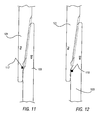
- an elastomer seal ring or region can also be utilized along with the described metal-to-metal seals, for example, as a gas containment seal in very severe environments or generally as a backup in cases where redundant seals are required.
- Figures 11 and 12 show such circumferential elastomeric seal rings 117. 119 on the pin end 121 and box end 123, respectively.
- the elastomeric seal rings 117, 119 can be formed of any suitable material commonly utilized in the relevant industry, for example, TEFLON, of fiberglass reinforced TEFLON, In the embodiment of the invention illustrated in Figures 11 and 12 , the elastomeric seal rings 117, 119 are located in the previously described "overlap regions" of the cylindrical sealing surfaces of the connection (generally at 79 in Figure 5 ).
- Figure 13 shows another embodiment of the invention in which the pin 125 and box 127 are provided with metal-to-metal cylindrical sealing surface 129, 131 spaced approximately equidistantly on either side of the pin and b ox ramp regions 133,135 respectively.
- the containment seal of the invention features ramp regions that simulate a pin swaging and/or box expansion resulting in the ability of the cylindrical sealing components 63, 63 ( Figures 2 and 3 ) to assemble with no interference or only very slight interference. This feature helps to guarantee that the cylindrical components of the seal will not gall during the primary or early stages of assembly. Generally the cylindrical components can have a slight overlap before receiving the appropriate interference required to seal off the gas or fluid pressures within the conduit.
- the seal assembly if desired, can also be provided with secondary ramp regions to gradually transfer the required interference or, if desired, radically transfer the interference to the cylindrical sealing surfaces of the connection.
- the cylindrical seal components of the seal are unique in that the interference which is produced does not gain or lose diametrical interference within a very generous stroke of assembly. This is of a particular advantage with connections that do not have shoulders acting as torque stops, as previously discussed.
- Another inherent benefit of the connection is the inherent damage protection of the cylindrical sealing components of the seal structure. Often during assembly, if the connection is not lubricated properly, conventional tapered metal-to-metal seals will gall and lose their integrity. This result occurs because of the long steady gradual gain of interference which develops heat and greatly enhances the possibility of balling up and separating the seal surfaces due to galling. Thus, even though the connection is designed with the correct diametrical interference, the connection would then leak because the surfaces would have a gap formed therebetween.
- the containment seal of the invention is provided with a separate ramp, which, even if improperly lubricated, or purposely non-lubricated, and subsequently damaged, does not affect the integrity of the sealed surfaces with the sealed surfaces remaining intact and seal integrity being preserved.
- the swaging/expanding ramps of the design may be provided with lubrication grooves and/or specially machined and/or textured surfaces or plated surfaces to retain lubrication during the mechanics of assembly.
- the ramps can be positioned higher than the cylindrical seal and/or elastomer ring to protect the sealing surfaces from stabbing and destabbing during assembly and disassembly operations.
- Higher interferences are generally required in larger diameter casing, for example, because the required interference is a function of diameter. Higher Interference can result in a higher danger of galling because of the possibility of heat generation.
- Lubrication grooves can be provided to ensure that the frictional effects are controlled during the assembly process.
- the axial position of the swaging/expanding ramps can be designed either before and/or after the cylindrical sealing surfaces.
- a single ramp without clearance areas may be used in designs where there are axial design limits to the overall length which may be employed.
- API 8 Round has a J area (designated as "J" in Figure 14 ) for example, that limits the design length, if the design criteria requires that the same coupling length be maintained.
- J J in Figure 14
- the present design allows the unique cylindrical sealing surfaces and ramp regions to be optimally sized, however, to accomplish a reliable seal.
- the ramp regions of the design can be provided in a simple form, such as plead in chamfer" for economical production.
- the containment seal structure of the invention will have full integrity and the same quantity of diametrical interference within a wide range of stroke, unlike the common tapered seals that gain or lose diametrical interference depending on the position falling short or overshooting the design criteria position, Positional tolerances of the present connection can be opened, thereby enabling the designer the opportunity of a higher degree of mass production while maintaining quality assurance standards. This provides the designer an opportunity to enhance the design performance of standard products such as the basic API connections,
- the design can include a clearance pocket for the ramp regions to provide clearance for raised material caused by inadvertently damaging the ramp regions.
- a clearance pocket By providing a clearance pocket, the raised damage area would not "jack open” the cylindrical seal component and destroy the integrity of the pressure containment.
- the ramp regions themselves also provide a zone or clearance which acts in the nature of a pressure relief valve where conditions require pressure relief.
- the separated ramp and cylindrical sealing surfaces and clearances which they provide offer unique advantages for a dope-less connection, since there is less likelihood of galling the metal-to-metal seal area in service.
- the design can include an elastomer ring to compliment the cylindrical seal and/or be used as the primary sealing structure.
Claims (26)
- Raccord fileté (11) ayant un joint d'étanchéité haute pression, métal-métal, cylindrique (13) capable de réaliser l'étanchéité à la fois des liquides et des gaz, le raccord comprenant :un premier élément ayant une extrémité de filetage femelle (17), l'extrémité de filetage femelle ayant une ouverture d'extrémité (19) définissant une surface intérieure (21) avec des filetages internes (23), les filetages internes étant définis par des crêtes (27) et des fonds (29) et des flancs opposés (33, 35) ;un second élément de couplage (37) ayant une extrémité de filetage mâle, l'extrémité de filetage mâle (39) ayant une surface extérieure (41) avec des filetages externes de couplage (43), les filetages externes ayant également des crêtes (45) et des fonds (47) et des flancs opposés, dont les sélectionnés se déplacent en mise en prise avec les filetages internes (23) du filetage femelle (17) lorsque le raccord est vissé ;une surface d'étanchéité généralement cylindrique (63) sur la surface intérieure de filetage femelle et une surface d'étanchéité généralement cylindrique de couplage (53) sur la surface extérieure de filetage mâle (41) qui forment un joint d'étanchéité principal suite au vissage du raccord ; etune région de rampe principale (59) formée sur la surface extérieure de filetage mâle (41) et une région de rampe principale de couplage (61) formée sur la surface intérieure de filetage femelle (21), les régions de rampe principales étant séparées de et/ou adjacentes aux surfaces d'étanchéité cylindriques (53, 63) qui forment le joint d'étanchéité principal, les régions de rampe principales (59, 61) étant positionnées par rapport aux surfaces d'étanchéité cylindriques (53, 63) pour entrer en contact et interférer avant la mise en prise totale des surfaces d'étanchéité cylindriques (53, 63) afin de simuler l'emboutissage du filetage mâle et l'expansion du filetage femelle avant la mise en prise totale des surfaces d'étanchéité cylindriques, moyennant quoi les surfaces d'étanchéité cylindriques (53, 63) s'assemblent avec peu ou pas d'interférence,caractérisé en ce que les régions de rampe principales (59, 61) sont sélectivement positionnées pour présenter un jeu suite à la mise en prise totale des surfaces d'étanchéité cylindriques (53, 63).
- Raccord fileté selon la revendication 1, dans lequel les surfaces d'étanchéité cylindriques de couplage (53, 63) sont positionnées sur la surface intérieure de filetage femelle (21) et sur la surface extérieure de filetage mâle (41) respectivement, afin de fournir un degré souhaité de chevauchement avant de recevoir une quantité d'interférence nécessaire pour former le joint d'étanchéité principal pour réaliser l'étanchéité des liquides et/ou des gaz à haute pression.
- Raccord fileté selon la revendication 2, dans lequel le degré souhaité de chevauchement est prédéterminé afin de garantir une pression d'appui qui résiste aux éraillures et à l'endommagement lorsque l'interférence est transférée des régions de rampe (59, 61) aux surfaces d'étanchéité cylindriques (53, 63) du raccord.
- Raccord fileté selon la revendication 3, dans lequel le raccord fileté (11) est prévu avec des régions de rampe secondaires de couplage pour transférer un degré progressif ou degré radical sélectionné d'interférence à une ou plusieurs des surfaces d'étanchéité cylindriques (53, 63).
- Raccord fileté selon la revendication 1, dans lequel le raccord (11) a des surfaces filetées de couplage (23, 43) qui sont choisies dans le groupe comprenant le filetage rond API en 8, le filetage rond API en 10, le filetage API Buttress et les raccords filetés premium sans épaulement pour servir d'arrêts de couple.
- Raccord fileté selon la revendication 1, dans lequel les régions de rampe de couplage (59, 61) sont prévues avec un élément sélectionné parmi des rainures de lubrification, des surfaces spécifiquement usinées, des surfaces spécifiquement texturées et des surfaces plaquées pour retenir la lubrification pendant la mécanique d'assemblage du raccord.
- Raccord fileté selon la revendication 1, dans lequel la région de rampe principale (59) du filetage mâle est positionnée entre une ou plusieurs surfaces d'étanchéité cylindriques de filetage mâle (53) et une étendue externe de l'extrémité de filetage mâle (39) de l'élément de raccordement.
- Raccord fileté selon la revendication 1, dans lequel la région de rampe principale (59) du filetage mâle est positionnée sur une surface qui est adjacente à la surface d'étanchéité cylindrique de filetage mâle (53) et d'un côté de la surface d'étanchéité cylindrique (53) qui est opposé à l'étendue externe de l'extrémité de filetage mâle (39) de l'élément de raccordement.
- Raccord fileté selon la revendication 1, dans lequel au moins une poche de jeu (55) est prévue de manière adjacente aux régions de rampe de couplage (59, 61) pour fournir le jeu pour un matériau en relief provoqué par l'endommagement involontaire aux régions de rampe.
- Raccord fileté selon la revendication 1, dans lequel le raccord est un raccord à épaulement.
- Raccord fileté selon la revendication 1, dans lequel une bague d'étanchéité élastomère (117, 119) est présente sur une surface sélectionnée parmi les surfaces de filetage mâle et de filetage femelle, en plus des surfaces d'étanchéité généralement cylindriques (53, 63).
- Raccord fileté selon la revendication 11, dans lequel la bague d'étanchéité élastomère (117, 119) est positionnée au niveau d'une région de chevauchement (79) d'une surface sélectionnée des surfaces d'étanchéité cylindriques (53, 63) de filetage mâle et de filetage femelle.
- Raccord fileté selon la revendication 1, dans lequel le raccord est sans dopage.
- Raccord fileté selon la revendication 11, dans lequel les régions de rampe (59, 61) sont positionnées dans des positions radiales sélectionnées qui sont supérieures aux surfaces d'étanchéité cylindriques (53, 63) respectives ou à la bague d'étanchéité élastomère (117, 119), comme observé en coupe, afin de protéger les surfaces d'étanchéité contre le guidage et l'action inverse du guidage pendant le montage et le démontage.
- Raccord fileté selon la revendication 1, dans lequel les régions de rampe (59, 61) constituent elles-mêmes une zone de jeu qui fournit une décharge de pression pendant l'assemblage.
- Raccord fileté selon la revendication 1 pour des tubes d'un champ pétrolifère ayant un joint d'étanchéité haute pression métal-métal cylindrique (13) pouvant réaliser l'étanchéité des liquides et des gaz de forage,
dans lequel les flancs opposés (33, 35) des filetages internes (23) comprennent des flancs de guidage (35) et des flancs de chargement (33) ;
dans lequel les flancs opposés des filetages externes (43) comprennent des flancs de guidage et des flancs de chargement, et
dans lequel les régions de rampe (59, 61) sont en interférence totale avant la mise en prise totale des régions d'étanchéité cylindriques et présentent un jeu suite à la mise en prise totale des régions d'étanchéité cylindriques. - Raccord fileté selon la revendication 16, dans lequel les régions de rampe principales (59, 61) sont positionnées sur la surface intérieure du filetage femelle (21) et sur la surface extérieure du filetage mâle (41) dans un emplacement présélectionné, moyennant quoi la région de rampe d'extrémité de filetage mâle (59) remonte tout d'abord et va sur la région de rampe principale de filetage femelle (61) lorsque le raccord est vissé, moyennant quoi la mise en prise des régions de rampe principales (59, 61) exerce une force radiale vers l'intérieur sur l'extrémité de filetage mâle (39) du second élément de tuyau de couplage (37).
- Raccord fileté selon la revendication 17, dans lequel la région de rampe principale d'extrémité de filetage mâle (59) redescend ensuite vers la région de rampe principale de filetage femelle (61) lorsque le raccord continue à être vissé, les régions de rampe principales (59, 61) entrent ensuite dans une région de jeu (55) lorsque les surfaces d'étanchéité cylindriques (53, 63) sont en contact et se déplacent dans une position complètement mise en prise.
- Raccord fileté selon la revendication 16, dans lequel les surfaces d'étanchéité cylindriques de couplage (53, 63) sont positionnées sur la surface intérieure de filetage femelle (21) et sur la surface extérieure de filetage mâle (41) respectivement, afin de fournir un degré souhaité de chevauchement avant de recevoir une quantité d'interférence nécessaire pour former le joint d'étanchéité principal afin de réaliser l'étanchéité des liquides et/ou des gaz à haute pression.
- Raccord fileté selon la revendication 19, dans lequel le degré souhaité de chevauchement est prédéterminé afin de garantir une pression d'appui qui résiste aux éraillures et à l'endommagement lorsque l'interférence est transférée des régions de rampe (59, 61) aux surfaces d'étanchéité cylindriques (53, 63) du raccord (11).
- Raccord fileté selon la revendication 16, dans lequel le raccord fileté (11) est prévu avec des régions de rampe secondaires de couplage pour transférer un degré progressif ou un degré radical sélectionné d'interférence aux surfaces d'étanchéité cylindriques (53, 63).
- Raccord fileté selon la revendication 16, dans lequel le raccord (11) a des surfaces filetées de couplage (23, 43) qui sont choisies dans le groupe comprenant un filetage rond API en 8, un filetage rond API en 10, un filetage API Buttress et des raccords filetés premium sans épaulement pour servir d'arrêts de couple.
- Raccord fileté selon la revendication 16, dans lequel les régions de rampe de couplage (59, 61) sont prévues avec un élément choisi parmi les rainures de lubrification, les surfaces spécifiquement usinées, les surfaces spécifiquement texturées et les surfaces plaquées pour retenir la lubrification pendant la mécanique d'assemblage du raccord.
- Raccord fileté selon la revendication 16, dans lequel la région de rampe principale de filetage mâle (59) est positionnée entre une ou plusieurs surfaces d'étanchéité cylindriques de filetage mâle (53) et une étendue externe de l'extrémité de filetage mâle (39) de l'élément de tuyau.
- Raccord fileté selon la revendication 16, dans lequel la région de rampe principale de filetage mâle (59) est positionnée sur une surface qui est adjacente à la surface d'étanchéité cylindrique de filetage mâle (53) et sur un côté de la surface d'étanchéité cylindrique (53) qui est opposé à l'étendue externe de l'extrémité de filetage mâle (39) de l'élément de tuyau.
- Raccord fileté selon la revendication 16, dans lequel au moins une poche de jeu (55) est prévue de manière adjacente aux régions de rampe de couplage (59, 61) pour fournir du jeu au matériau en relief provoqué par l'endommagement involontaire aux régions de rampe.
Applications Claiming Priority (3)
| Application Number | Priority Date | Filing Date | Title |
|---|---|---|---|
| US10/285,911 US6832789B2 (en) | 2002-11-01 | 2002-11-01 | Threaded pipe connection with cylindrical metal-to-metal, high pressure containment seal |
| US285911 | 2002-11-01 | ||
| PCT/US2003/026116 WO2004042263A2 (fr) | 2002-11-01 | 2003-08-21 | Raccord de tuyauterie filete a joint d'etancheite haute pression, metal-metal cylindrique |
Publications (3)
| Publication Number | Publication Date |
|---|---|
| EP1556645A2 EP1556645A2 (fr) | 2005-07-27 |
| EP1556645A4 EP1556645A4 (fr) | 2010-08-04 |
| EP1556645B1 true EP1556645B1 (fr) | 2012-11-28 |
Family
ID=32175295
Family Applications (1)
| Application Number | Title | Priority Date | Filing Date |
|---|---|---|---|
| EP03749089A Expired - Lifetime EP1556645B1 (fr) | 2002-11-01 | 2003-08-21 | Raccord de tuyauterie filete a joint d'etancheite haute pression, metal-metal cylindrique |
Country Status (6)
| Country | Link |
|---|---|
| US (1) | US6832789B2 (fr) |
| EP (1) | EP1556645B1 (fr) |
| AU (1) | AU2003268140A1 (fr) |
| CA (1) | CA2502611C (fr) |
| MX (1) | MXPA05004660A (fr) |
| WO (1) | WO2004042263A2 (fr) |
Families Citing this family (31)
| Publication number | Priority date | Publication date | Assignee | Title |
|---|---|---|---|---|
| US6497880B1 (en) * | 1998-12-08 | 2002-12-24 | Stressgen Biotechnologies Corporation | Heat shock genes and proteins from Neisseria meningitidis, Candida glabrata and Aspergillus fumigatus |
| GB0317395D0 (en) * | 2003-07-25 | 2003-08-27 | Weatherford Lamb | Sealing expandable tubing |
| US8177262B2 (en) * | 2005-07-28 | 2012-05-15 | Hydril Company Lp | Mid-seal for expandable connections |
| US7549682B2 (en) * | 2005-09-19 | 2009-06-23 | Vetco Gray Inc. | Threaded pipe connector |
| US7686350B2 (en) * | 2006-03-30 | 2010-03-30 | Hydril Llc | Mismatched flanks for a wedge thread |
| US7588269B2 (en) * | 2006-09-26 | 2009-09-15 | Gandy Technologies Corporation | Z-shaped thread form for tubular connections |
| US7690697B2 (en) * | 2007-05-09 | 2010-04-06 | Gandy Technologies Corp. | Thread form for tubular connections |
| US7780202B2 (en) * | 2007-09-05 | 2010-08-24 | Grant Prideco, Lp | Oilfield tubular connection with increased compression capacity |
| US20100052319A1 (en) * | 2008-08-28 | 2010-03-04 | Mohawk Energy Ltd. | Dual Seal Expandable Tubular Connection |
| CN103791181B (zh) * | 2008-11-04 | 2017-09-26 | Vam美国有限责任公司 | 抗压性能提高的油田用管状接头 |
| US8136846B2 (en) * | 2008-11-17 | 2012-03-20 | Gandy Technologies Corporation | Cylindrical tapered thread form for tubular connections |
| US8267436B2 (en) * | 2009-07-08 | 2012-09-18 | Gandy Technologies Corporation | Arrow-shaped thread form for tubular connections |
| US20110084477A1 (en) * | 2009-10-13 | 2011-04-14 | Hydril Company | Wedge threads with a solid lubricant coating |
| US8985640B2 (en) | 2009-11-04 | 2015-03-24 | Torquelock Corporation | Threaded pipe connection with a pressure energized flex-seal |
| US20110101684A1 (en) * | 2009-11-04 | 2011-05-05 | Gandy Technologies Corporation | Threaded Pipe Connection with a Pressure Energized Flex Seal |
| GB201005247D0 (en) * | 2010-03-29 | 2010-05-12 | Hsc Fzco | An improved seal between pipes |
| FR2961576B1 (fr) * | 2010-06-17 | 2012-08-03 | Vallourec Mannesmann Oil & Gas | Joint filete et procede de realisation |
| DE102010030754A1 (de) * | 2010-06-30 | 2012-01-05 | Klaus Wohlfarth | Verbindungsanordnung |
| GB201019413D0 (en) | 2010-11-17 | 2010-12-29 | Hsc Fzco | An improved seal between pipes |
| US9243729B2 (en) * | 2011-02-21 | 2016-01-26 | Hunting Energy Services, Inc. | Position make-up indicator system |
| US9869414B2 (en) * | 2011-05-24 | 2018-01-16 | Ultra Premium Oilfield Services, Ltd. | Tubular connection and associated threadform |
| FR2979968B1 (fr) * | 2011-09-13 | 2014-06-27 | Vallourec Mannesmann Oil & Gas | Ensemble pour la realisation d'un joint filete pour le forage et l'exploitation des puits d'hydrocarbures et joint filete resultant |
| US8894101B2 (en) * | 2012-09-07 | 2014-11-25 | Vetco Gray Inc. | Protected integral metal to metal seal |
| US9677346B2 (en) | 2012-11-28 | 2017-06-13 | Ultra Premium Oilfield Services, Ltd. | Tubular connection with helically extending torque shoulder |
| US9869139B2 (en) * | 2012-11-28 | 2018-01-16 | Ultra Premium Oilfield Services, Ltd. | Tubular connection with helically extending torque shoulder |
| FR3006029B1 (fr) * | 2013-05-23 | 2015-11-13 | Vallourec Mannesmann Oil & Gas | Ensemble pour la realisation d'un joint filete pour le forage et l'exploitation des puits d'hydrocarbures et joint filete resultant |
| US10428594B2 (en) | 2013-11-22 | 2019-10-01 | Vetco Gray, LLC | Alignment guide feature for metal to metal seal protection on mechanical connections and couplings |
| FR3098878B1 (fr) * | 2019-07-19 | 2021-07-30 | Vallourec Oil & Gas France | Joint fileté pour colonne de cuvelage de puits de pétrole |
| WO2021116765A1 (fr) | 2019-12-12 | 2021-06-17 | Voestalpine Tubulars Gmbh & Co Kg | Raccord tubulaire fileté doté d'une caractéristique de filtre à particules de taille de grain |
| WO2022108656A1 (fr) * | 2020-11-19 | 2022-05-27 | Schlumberger Technology Corporation | Système d'étanchéité pour éléments annulaires |
| US11448345B2 (en) * | 2020-11-20 | 2022-09-20 | Precision Couplings LLC | Coupling |
Family Cites Families (17)
| Publication number | Priority date | Publication date | Assignee | Title |
|---|---|---|---|---|
| US4384737A (en) | 1980-04-25 | 1983-05-24 | Republic Steel Corporation | Threaded joint for well casing and tubing |
| US4662659A (en) * | 1983-01-17 | 1987-05-05 | Hydril Company | Tubular joint with trapped mid-joint metal-to-metal seal having unequal tapers |
| US4537429A (en) * | 1983-04-26 | 1985-08-27 | Hydril Company | Tubular connection with cylindrical and tapered stepped threads |
| US4692988A (en) * | 1986-08-19 | 1987-09-15 | Nowsco Well Service (U.K.) Limited | Screw thread protection |
| US5338074A (en) | 1989-03-02 | 1994-08-16 | The Hydril Company | Threaded pipe connection |
| US5064224A (en) * | 1989-03-08 | 1991-11-12 | Baroid Technology, Inc. | Oil field tubular connection |
| US5066052A (en) * | 1989-03-08 | 1991-11-19 | Baroid Technology, Inc. | Threaded pipe joint having improved seal ring entrapment |
| US5154452A (en) * | 1991-09-18 | 1992-10-13 | Frederick William Johnson | Tubular connection with S-thread form for clamping center seal |
| US5415442A (en) * | 1992-03-09 | 1995-05-16 | Marubeni Tubulars, Inc. | Stabilized center-shoulder-sealed tubular connection |
| DE69535474T2 (de) * | 1994-10-19 | 2008-01-03 | Vallourec Mannesmann Oil & Gas France | Gewindeverbindung für Rohre |
| EP0916883B1 (fr) * | 1997-05-30 | 2006-06-28 | Sumitomo Metal Industries, Ltd. | Joint a vis pour tuyau de puits de petrole |
| US6158785A (en) | 1998-08-06 | 2000-12-12 | Hydril Company | Multi-start wedge thread for tubular connection |
| US6254146B1 (en) | 1999-04-23 | 2001-07-03 | John Gandy Corporation | Thread form with multifacited flanks |
| WO2000066928A1 (fr) * | 1999-04-30 | 2000-11-09 | Grant Prideco, Inc. | Raccord filete a caracteristique de compression elevee |
| DE19955377C2 (de) * | 1999-11-10 | 2002-05-02 | Mannesmann Ag | Rohrverbindung |
| US6478344B2 (en) * | 2000-09-15 | 2002-11-12 | Abb Vetco Gray Inc. | Threaded connector |
| US6530607B1 (en) * | 2000-11-06 | 2003-03-11 | Hydril Company | Two-step threaded connector having differential thread width |
-
2002
- 2002-11-01 US US10/285,911 patent/US6832789B2/en not_active Expired - Lifetime
-
2003
- 2003-08-21 CA CA002502611A patent/CA2502611C/fr not_active Expired - Fee Related
- 2003-08-21 EP EP03749089A patent/EP1556645B1/fr not_active Expired - Lifetime
- 2003-08-21 WO PCT/US2003/026116 patent/WO2004042263A2/fr not_active Application Discontinuation
- 2003-08-21 MX MXPA05004660A patent/MXPA05004660A/es active IP Right Grant
- 2003-08-21 AU AU2003268140A patent/AU2003268140A1/en not_active Abandoned
Also Published As
| Publication number | Publication date |
|---|---|
| WO2004042263A2 (fr) | 2004-05-21 |
| EP1556645A4 (fr) | 2010-08-04 |
| AU2003268140A8 (en) | 2004-06-07 |
| EP1556645A2 (fr) | 2005-07-27 |
| AU2003268140A1 (en) | 2004-06-07 |
| US20040084901A1 (en) | 2004-05-06 |
| WO2004042263A3 (fr) | 2004-09-16 |
| MXPA05004660A (es) | 2005-09-20 |
| US6832789B2 (en) | 2004-12-21 |
| CA2502611A1 (fr) | 2004-05-21 |
| CA2502611C (fr) | 2008-07-22 |
Similar Documents
| Publication | Publication Date | Title |
|---|---|---|
| EP1556645B1 (fr) | Raccord de tuyauterie filete a joint d'etancheite haute pression, metal-metal cylindrique | |
| US7527304B2 (en) | Floating wedge thread for tubular connection | |
| EP1106778B1 (fr) | Garniture d'étanchéité pour des assemblages tubulaires extensibles | |
| US6270127B1 (en) | Two-step, low torque wedge thread for tubular connector | |
| EP1302623B1 (fr) | Filetage de coin avec epaulement de couple | |
| US3047316A (en) | Packed pin and box drill pipe coupling with means preventing extrusion of packing ring | |
| US6626471B2 (en) | Double flex seal for tubular connection | |
| CA2725126C (fr) | Raccordement de masse-tige | |
| WO2004060590A2 (fr) | Raccord filete a liberation de pression | |
| CA2780385C (fr) | Raccord de tuyau filete a un joint flexible active par pression | |
| EP0386373A2 (fr) | Connexion pour tubages de pétrole | |
| AU2018280170B2 (en) | Compression resistant threaded connection | |
| US9683684B1 (en) | Tubular coupling | |
| US8985640B2 (en) | Threaded pipe connection with a pressure energized flex-seal | |
| US4750761A (en) | Oilwell tubular connection | |
| US11466800B2 (en) | Tubular coupling | |
| US20040108720A1 (en) | Double flex seal for tubular connection | |
| US4582349A (en) | Plastically deformed seals in downhole tools | |
| CA2091854C (fr) | Connecteur tubulaire filete autosertisseur |
Legal Events
| Date | Code | Title | Description |
|---|---|---|---|
| PUAI | Public reference made under article 153(3) epc to a published international application that has entered the european phase |
Free format text: ORIGINAL CODE: 0009012 |
|
| 17P | Request for examination filed |
Effective date: 20050419 |
|
| AK | Designated contracting states |
Kind code of ref document: A2 Designated state(s): AT BE BG CH CY CZ DE DK EE ES FI FR GB GR HU IE IT LI LU MC NL PT RO SE SI SK TR |
|
| AX | Request for extension of the european patent |
Extension state: AL LT LV MK |
|
| DAX | Request for extension of the european patent (deleted) | ||
| A4 | Supplementary search report drawn up and despatched |
Effective date: 20100706 |
|
| RIC1 | Information provided on ipc code assigned before grant |
Ipc: F16L 35/00 20060101AFI20050420BHEP Ipc: E21B 17/042 20060101ALI20100630BHEP |
|
| 17Q | First examination report despatched |
Effective date: 20101004 |
|
| REG | Reference to a national code |
Ref country code: DE Ref legal event code: R079 Ref document number: 60342714 Country of ref document: DE Free format text: PREVIOUS MAIN CLASS: F16L0035000000 Ipc: F16L0015040000 |
|
| GRAP | Despatch of communication of intention to grant a patent |
Free format text: ORIGINAL CODE: EPIDOSNIGR1 |
|
| RIC1 | Information provided on ipc code assigned before grant |
Ipc: F16L 15/00 20060101ALI20120410BHEP Ipc: F16L 15/04 20060101AFI20120410BHEP Ipc: E21B 17/042 20060101ALI20120410BHEP |
|
| GRAS | Grant fee paid |
Free format text: ORIGINAL CODE: EPIDOSNIGR3 |
|
| GRAA | (expected) grant |
Free format text: ORIGINAL CODE: 0009210 |
|
| AK | Designated contracting states |
Kind code of ref document: B1 Designated state(s): AT BE BG CH CY CZ DE DK EE ES FI FR GB GR HU IE IT LI LU MC NL PT RO SE SI SK TR |
|
| REG | Reference to a national code |
Ref country code: GB Ref legal event code: FG4D |
|
| REG | Reference to a national code |
Ref country code: CH Ref legal event code: EP |
|
| REG | Reference to a national code |
Ref country code: AT Ref legal event code: REF Ref document number: 586376 Country of ref document: AT Kind code of ref document: T Effective date: 20121215 |
|
| REG | Reference to a national code |
Ref country code: IE Ref legal event code: FG4D |
|
| REG | Reference to a national code |
Ref country code: DE Ref legal event code: R096 Ref document number: 60342714 Country of ref document: DE Effective date: 20130124 |
|
| REG | Reference to a national code |
Ref country code: AT Ref legal event code: MK05 Ref document number: 586376 Country of ref document: AT Kind code of ref document: T Effective date: 20121128 |
|
| REG | Reference to a national code |
Ref country code: NL Ref legal event code: VDEP Effective date: 20121128 |
|
| PG25 | Lapsed in a contracting state [announced via postgrant information from national office to epo] |
Ref country code: ES Free format text: LAPSE BECAUSE OF FAILURE TO SUBMIT A TRANSLATION OF THE DESCRIPTION OR TO PAY THE FEE WITHIN THE PRESCRIBED TIME-LIMIT Effective date: 20130311 Ref country code: FI Free format text: LAPSE BECAUSE OF FAILURE TO SUBMIT A TRANSLATION OF THE DESCRIPTION OR TO PAY THE FEE WITHIN THE PRESCRIBED TIME-LIMIT Effective date: 20121128 Ref country code: SE Free format text: LAPSE BECAUSE OF FAILURE TO SUBMIT A TRANSLATION OF THE DESCRIPTION OR TO PAY THE FEE WITHIN THE PRESCRIBED TIME-LIMIT Effective date: 20121128 |
|
| PG25 | Lapsed in a contracting state [announced via postgrant information from national office to epo] |
Ref country code: SI Free format text: LAPSE BECAUSE OF FAILURE TO SUBMIT A TRANSLATION OF THE DESCRIPTION OR TO PAY THE FEE WITHIN THE PRESCRIBED TIME-LIMIT Effective date: 20121128 Ref country code: CY Free format text: LAPSE BECAUSE OF FAILURE TO SUBMIT A TRANSLATION OF THE DESCRIPTION OR TO PAY THE FEE WITHIN THE PRESCRIBED TIME-LIMIT Effective date: 20121128 Ref country code: BE Free format text: LAPSE BECAUSE OF FAILURE TO SUBMIT A TRANSLATION OF THE DESCRIPTION OR TO PAY THE FEE WITHIN THE PRESCRIBED TIME-LIMIT Effective date: 20121128 Ref country code: PT Free format text: LAPSE BECAUSE OF FAILURE TO SUBMIT A TRANSLATION OF THE DESCRIPTION OR TO PAY THE FEE WITHIN THE PRESCRIBED TIME-LIMIT Effective date: 20130328 Ref country code: GR Free format text: LAPSE BECAUSE OF FAILURE TO SUBMIT A TRANSLATION OF THE DESCRIPTION OR TO PAY THE FEE WITHIN THE PRESCRIBED TIME-LIMIT Effective date: 20130301 |
|
| PG25 | Lapsed in a contracting state [announced via postgrant information from national office to epo] |
Ref country code: AT Free format text: LAPSE BECAUSE OF FAILURE TO SUBMIT A TRANSLATION OF THE DESCRIPTION OR TO PAY THE FEE WITHIN THE PRESCRIBED TIME-LIMIT Effective date: 20121128 |
|
| PG25 | Lapsed in a contracting state [announced via postgrant information from national office to epo] |
Ref country code: DK Free format text: LAPSE BECAUSE OF FAILURE TO SUBMIT A TRANSLATION OF THE DESCRIPTION OR TO PAY THE FEE WITHIN THE PRESCRIBED TIME-LIMIT Effective date: 20121128 Ref country code: EE Free format text: LAPSE BECAUSE OF FAILURE TO SUBMIT A TRANSLATION OF THE DESCRIPTION OR TO PAY THE FEE WITHIN THE PRESCRIBED TIME-LIMIT Effective date: 20121128 Ref country code: CZ Free format text: LAPSE BECAUSE OF FAILURE TO SUBMIT A TRANSLATION OF THE DESCRIPTION OR TO PAY THE FEE WITHIN THE PRESCRIBED TIME-LIMIT Effective date: 20121128 Ref country code: BG Free format text: LAPSE BECAUSE OF FAILURE TO SUBMIT A TRANSLATION OF THE DESCRIPTION OR TO PAY THE FEE WITHIN THE PRESCRIBED TIME-LIMIT Effective date: 20130228 Ref country code: SK Free format text: LAPSE BECAUSE OF FAILURE TO SUBMIT A TRANSLATION OF THE DESCRIPTION OR TO PAY THE FEE WITHIN THE PRESCRIBED TIME-LIMIT Effective date: 20121128 |
|
| PG25 | Lapsed in a contracting state [announced via postgrant information from national office to epo] |
Ref country code: IT Free format text: LAPSE BECAUSE OF FAILURE TO SUBMIT A TRANSLATION OF THE DESCRIPTION OR TO PAY THE FEE WITHIN THE PRESCRIBED TIME-LIMIT Effective date: 20121128 Ref country code: RO Free format text: LAPSE BECAUSE OF FAILURE TO SUBMIT A TRANSLATION OF THE DESCRIPTION OR TO PAY THE FEE WITHIN THE PRESCRIBED TIME-LIMIT Effective date: 20121128 Ref country code: NL Free format text: LAPSE BECAUSE OF FAILURE TO SUBMIT A TRANSLATION OF THE DESCRIPTION OR TO PAY THE FEE WITHIN THE PRESCRIBED TIME-LIMIT Effective date: 20121128 |
|
| PLBE | No opposition filed within time limit |
Free format text: ORIGINAL CODE: 0009261 |
|
| STAA | Information on the status of an ep patent application or granted ep patent |
Free format text: STATUS: NO OPPOSITION FILED WITHIN TIME LIMIT |
|
| 26N | No opposition filed |
Effective date: 20130829 |
|
| REG | Reference to a national code |
Ref country code: DE Ref legal event code: R097 Ref document number: 60342714 Country of ref document: DE Effective date: 20130829 |
|
| REG | Reference to a national code |
Ref country code: CH Ref legal event code: PL |
|
| PG25 | Lapsed in a contracting state [announced via postgrant information from national office to epo] |
Ref country code: MC Free format text: LAPSE BECAUSE OF FAILURE TO SUBMIT A TRANSLATION OF THE DESCRIPTION OR TO PAY THE FEE WITHIN THE PRESCRIBED TIME-LIMIT Effective date: 20121128 Ref country code: CH Free format text: LAPSE BECAUSE OF NON-PAYMENT OF DUE FEES Effective date: 20130831 Ref country code: LI Free format text: LAPSE BECAUSE OF NON-PAYMENT OF DUE FEES Effective date: 20130831 Ref country code: DE Free format text: LAPSE BECAUSE OF NON-PAYMENT OF DUE FEES Effective date: 20140301 |
|
| REG | Reference to a national code |
Ref country code: DE Ref legal event code: R119 Ref document number: 60342714 Country of ref document: DE Effective date: 20140301 |
|
| PG25 | Lapsed in a contracting state [announced via postgrant information from national office to epo] |
Ref country code: TR Free format text: LAPSE BECAUSE OF FAILURE TO SUBMIT A TRANSLATION OF THE DESCRIPTION OR TO PAY THE FEE WITHIN THE PRESCRIBED TIME-LIMIT Effective date: 20121128 |
|
| PG25 | Lapsed in a contracting state [announced via postgrant information from national office to epo] |
Ref country code: HU Free format text: LAPSE BECAUSE OF FAILURE TO SUBMIT A TRANSLATION OF THE DESCRIPTION OR TO PAY THE FEE WITHIN THE PRESCRIBED TIME-LIMIT; INVALID AB INITIO Effective date: 20030821 Ref country code: LU Free format text: LAPSE BECAUSE OF NON-PAYMENT OF DUE FEES Effective date: 20130821 |
|
| REG | Reference to a national code |
Ref country code: FR Ref legal event code: PLFP Year of fee payment: 14 |
|
| REG | Reference to a national code |
Ref country code: FR Ref legal event code: PLFP Year of fee payment: 15 |
|
| REG | Reference to a national code |
Ref country code: FR Ref legal event code: PLFP Year of fee payment: 16 |
|
| PGFP | Annual fee paid to national office [announced via postgrant information from national office to epo] |
Ref country code: IE Payment date: 20190827 Year of fee payment: 17 Ref country code: FR Payment date: 20190822 Year of fee payment: 17 |
|
| PGFP | Annual fee paid to national office [announced via postgrant information from national office to epo] |
Ref country code: GB Payment date: 20190821 Year of fee payment: 17 |
|
| GBPC | Gb: european patent ceased through non-payment of renewal fee |
Effective date: 20200821 |
|
| PG25 | Lapsed in a contracting state [announced via postgrant information from national office to epo] |
Ref country code: FR Free format text: LAPSE BECAUSE OF NON-PAYMENT OF DUE FEES Effective date: 20200831 |
|
| PG25 | Lapsed in a contracting state [announced via postgrant information from national office to epo] |
Ref country code: IE Free format text: LAPSE BECAUSE OF NON-PAYMENT OF DUE FEES Effective date: 20200821 Ref country code: GB Free format text: LAPSE BECAUSE OF NON-PAYMENT OF DUE FEES Effective date: 20200821 |