EP1555629A2 - Acoustic Touchscreen with Array of Reflectors Shaped to Focus Acoustic Wave Energy - Google Patents
Acoustic Touchscreen with Array of Reflectors Shaped to Focus Acoustic Wave Energy Download PDFInfo
- Publication number
- EP1555629A2 EP1555629A2 EP05100046A EP05100046A EP1555629A2 EP 1555629 A2 EP1555629 A2 EP 1555629A2 EP 05100046 A EP05100046 A EP 05100046A EP 05100046 A EP05100046 A EP 05100046A EP 1555629 A2 EP1555629 A2 EP 1555629A2
- Authority
- EP
- European Patent Office
- Prior art keywords
- array
- reflective
- substrate
- touchscreen
- elements
- Prior art date
- Legal status (The legal status is an assumption and is not a legal conclusion. Google has not performed a legal analysis and makes no representation as to the accuracy of the status listed.)
- Granted
Links
Images


Classifications
-
- G—PHYSICS
- G06—COMPUTING OR CALCULATING; COUNTING
- G06F—ELECTRIC DIGITAL DATA PROCESSING
- G06F3/00—Input arrangements for transferring data to be processed into a form capable of being handled by the computer; Output arrangements for transferring data from processing unit to output unit, e.g. interface arrangements
- G06F3/01—Input arrangements or combined input and output arrangements for interaction between user and computer
- G06F3/03—Arrangements for converting the position or the displacement of a member into a coded form
- G06F3/041—Digitisers, e.g. for touch screens or touch pads, characterised by the transducing means
- G06F3/043—Digitisers, e.g. for touch screens or touch pads, characterised by the transducing means using propagating acoustic waves
- G06F3/0436—Digitisers, e.g. for touch screens or touch pads, characterised by the transducing means using propagating acoustic waves in which generating transducers and detecting transducers are attached to a single acoustic waves transmission substrate
Definitions
- the present invention relates to acoustic touchscreens and, in particular, to acoustic touchscreens employing focusing-shaped reflective arrays to transmit and receive acoustic signals into and out of a touch-sensitive area.
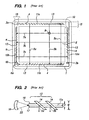
- FIG. 1 illustrates the operation of a conventional acoustic touchscreen 1 having an active or "touch-sensitive" area 2.
- a first transmitting transducer 3a is positioned outside of the touch-sensitive area 2 and acoustically coupled to the surface of touchscreen 1.
- the transducer 3a sends an acoustic signal in the form of an acoustic wave (or beam) 11a traveling parallel to the top edge, and generally in the plane of, touchscreen 1.
- a first linear array 13 of acoustically reflective elements 4 Aligned in the transmission path of acoustic wave 11a is a first linear array 13 of acoustically reflective elements 4, each of which partially reflects (by approximately 90 degrees) and partially transmits (i.e., passes through) the acoustic wave 11a, creating a plurality of acoustic waves (exemplary ones shown as 5a, 5b, and 5c) traveling vertically (parallel to the Y-axis) across touch-sensitive area 2.
- an "acoustically reflective" element includes any element which at least partially reflects acoustic wave energy, even if such element may actually pass through nearly all of the wave energy.
- an individual reflective array element reflects as little as 1% or less of an acoustic wave into the touch-sensitive area, while passing through the remaining wave energy to the next successive array element.
- the spacing of the reflective array elements 4 is variable to compensate for the attenuation of the acoustic waves with increasing distance from first transmitter 3a. Alternately, such compensation may be provided by densely spaced reflective array elements with variable reflective strengths.
- the acoustic waves 5a, 5b, and 5c are again reflected by approximately 90 degrees (shown by arrow 11b) by a second linear array 13 of acoustically reflective elements 4 towards a first receiving transducer 6a, where they are detected and converted to electrical signals for data processing.
- a second linear array 13 of acoustically reflective elements 4 are again reflected by approximately 90 degrees (shown by arrow 11b) by a second linear array 13 of acoustically reflective elements 4 towards a first receiving transducer 6a, where they are detected and converted to electrical signals for data processing.
- the left and right edges of touchscreen 1 are located a similar arrangement.
- a second transmitting transducer 3b generates an acoustic wave 12a along the left edge, and a third linear array 13 of acoustically reflective elements 4 creates therefrom a plurality of acoustic waves (exemplary 7a, 7b, and 7c) traveling horizontally (parallel to the X-axis) across touch-sensitive area 2. Acoustic waves 7a, 7b, and 7c are redirected (arrow 12b) by a fourth linear array 13 of acoustically reflective elements 4 towards receiving transducer 6b, where they are detected and converted to electrical signals.
- a touchscreen can be designed with only two transducers by using a common transmit/receive transducer scheme as shown in Fig. 11 of U.S. Patent No. 4,880,665.
- a bezel overlays the touchscreen 1, concealing the transmitting and receiving transducers, the reflective elements, and other components, and defining the touch-sensitive area 2.
- This arrangement protects the concealed components from contamination and/or damage, presents a more aesthetically pleasing appearance, and defines the touch-sensitive area for the user.
- the touch-sensitive area 2 is surrounded by border regions 15 (only two labeled), where the reflective elements 4 and the transmitting and receiving transducers 3a, 3b, 6a, and 6b are located. Reducing the width of border regions 15 increases the percentage of the frontal area of the device that may be allocated to touch-sensitive area 2, as well as conveying a less cumbersome, sleeker design.
- FIG. 2 illustrates a transducer 16 and a reflective array 13 of an acoustic touchscreen that allows for a narrower border region than in conventional touchscreens.
- the path of the acoustic wave 11a is confined by an acoustic waveguide core 18.
- the reflective array 13 includes a plurality of acoustically reflective elements 14 cooperating with the waveguide core 18.
- the reflective elements 14 are overlaid on top of the waveguide core 18 at predetermined intervals, which effectively allows the reflective elements 14 to partially deflect energy from the incoming acoustic wave 11a across the touch-sensitive area as the acoustic waves 5a and 5b.
- a significant portion of the acoustic energy is confined to the array 14 of width w as a result of the inclusion of the waveguide core 18 of width y. Because the width of the acoustic wave energy can be controlled by the width of the waveguide core 18, the reflectors 14 may be made correspondingly narrower than conventional ones, but yet deflect a sufficient amount of acoustic energy across the touch-sensitive area for touch-sensing purposes
- an acoustic touchscreen is provided with an array of focusing-shaped, acoustically reflective elements positioned to transmit or receive acoustic signals into or out of a touch-sensitive area.
- a "focusing-shaped" reflective array element is one that tends to focus the portion (typically most all) of the acoustic wave energy being passed through the respective element to an area proximate a center line axis of the array.
- the focusing-shaped elements are located on or in the touchscreen substrate in the path of the acoustic wave energy, and have a velocity-slowing effect, or equivalently a phase-delaying effect, relative to the surrounding touchscreen substrate.
- Each element's velocity-slowing effect strengthens proximate its center by varying one or both of its width and height along its transverse dimension, (i.e., along its dimension transverse to the propagating wave energy), with a maximum width and/or height proximate its center, tapering to a minimum width and/or height at its transverse ends.
- the natural divergence of the wave energy is countered by the tendency of the elements to pull the wave energy towards the center line of the array axis, where the maximum propagation delay through the respective elements is encountered.
- the focusing-shaped elements provide waveguide functionality without requiring a separate waveguide core structure.
- a touchscreen in an exemplary embodiment, includes a substrate capable of propagating acoustic waves and having a touch-sensitive area.
- a linear array of focusing-shaped acoustically reflective elements is provided lying in or on the substrate and positioned to transmit or receive acoustic signals into or out of the touch-sensitive area.
- the reflective elements may have a varying width dimension, with a maximum width proximate their center.
- the reflective elements may have a varying height dimension, with a maximum height proximate their center.
- the reflective elements are grooves located in a surface of the substrate and positioned at an angle relative to an array axis, each element having a having a varying depth from the substrate surface, with a maximum depth proximate its center.
- the groves may be at least partially filled with a medium having a different (i.e., slower) acoustic wave propagation speed than the substrate medium.
- the reflective array elements may be located on a surface of, or partially or fully embedded in, the substrate.
- the touchscreen further includes a waveguide core substantially aligned with the reflective array axis.
- FIG. 1 is a schematic plan view of a conventional acoustic touchscreen.
- FIG. 2 is a waveguide-reflective array combination for use in an acoustic touchscreen.
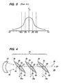
- FIG. 3 is a schematic graph of acoustic energy along the width of the waveguide-reflective array of FIG. 2.
- FIG. 4 is a plan view of an exemplary embodiment of a focusing-shaped reflective array in accordance with the present invention.
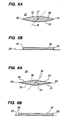
- FIGS. 5A and 5B are plan and side views, respectively, of a focusing-shaped reflective element of the array of FIG. 4.
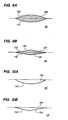
- FIGS. 6A and 6B are plan and side views of an alternate embodiment of a focusing-shaped reflective element for use in the array of FIG. 4.
- FIGS. 7A and 7B are plan and side views of another embodiment of a focusing-shaped reflective element for use in the array of FIG. 4.
- FIGS. 8A and 8B are plan and side views of yet another embodiment of a focusing-shaped reflective element for use in the array of FIG. 4.
- FIGS. 9A and 9B are sectional side views of still further embodiments of focusing-shaped reflective array elements for use in the array of FIG. 4.
- FIGS. 10A, 10B and 10C are sectional side views of yet further embodiments of focusing reflective array elements for use in the array of FIG. 4.
- FIG. 11 is a plan view of a further exemplary embodiment of a focusing-shaped reflective array cooperating with a waveguide core in accordance with a further aspect of the present invention.
- FIG. 4 illustrates a transducer 22 and a linear reflective array 24 for use in transmitting an acoustic beam 34 emitted from the transducer 22 across a touch-sensitive area (not shown) of an acoustic-touchscreen (e.g., glass) substrate 25.
- the reflective array 24 includes a plurality of acoustically reflective focusing-shaped elements 26.
- the reflective elements 26 are lens-shaped, i.e., having a parabolic profile, and are positioned at an angle (approximately 45 degrees) relative to an axis 28 of the reflective array 24.
- Each reflective element 26 has a proximal facing convex surface 30 and a distal facing convex surface 32, the respective surfaces 30 and 32 tapering to respective transverse ends 39 and 40 of the element 26.
- FIGS. 5A and 5B are plan and side views of the array elements 26 shown in FIG. 4, which are formed on a surface of the substrate 25.
- the array axis 28 is aligned with the transmission path of the acoustic beam 34, such that each element 26 partially reflects (by approximately 90 degrees) and partially transmits (i.e., passes through) the acoustic beam 34, creating a plurality of acoustic waves (exemplary ones shown as 34a, 34b, and 34c) traveling into the touch-sensitive area (not shown). Because of the focusing-shape of the reflective elements 26, that portion (typically nearly all) of the energy of the acoustic beam 34 passing through the respective elements 26 is focused to a relatively narrow area proximate a center line 36 passing through a center point 37 of each of the respective elements 26 and parallel to the array axis 28.
- each element imposes a velocity-slowing effect on the acoustic beam 34, which strengthens proximate its respective center point 37.
- This may be accomplished by varying one or both of a width or height of the element 26 along its transverse dimension, i.e., along that dimension transverse to the propagating wave energy, with a maximum width and/or height proximate its center 37, tapering to a minimum width and/or height at its transverse ends 39, 40.
- the natural divergence of the wave energy is countered by the tendency of the elements to pull the wave energy of the beam 34 towards the center line 36 of the array axis 28, where the maximum propagation delay through the respective elements 26 is encountered.
- the reflective array elements 26 do not so much focus the acoustic beam 34, but instead effectively cancel the de-focusing effect of the natural diffractive spreading of the beam 34, so that the transverse width of the beam 34 (i.e., relative to the array axis 28) remains substantially the same when it reaches each successive reflective element 26 in the array 24.
- the elements 26 may be made correspondingly narrower than in conventional reflective arrays used in acoustic touchscreens, but still deflect a sufficient amount of acoustic energy across the touch-sensitive area of the substrate 25 for touch-sensing purposes.
- the wave energy of the acoustic beam 34 propagates in the substrate 25, with a significant power density at the surface.
- the propagation of the acoustic beam 34 is described herein as being two-dimensional in the surface of the substrate 25.
- the reflective array elements 26 located on or near the surface sufficiently interact with the wave energy to affect wave propagation velocities as described above, thereby "focusing" the energy of the beam 34 proximate the center line 36 of the array axis 28.
- the transmitting transducer 22 can be a focusing transducer, in which the beam 34 of acoustic waves comes to a focus at a focal location 38 proximate the center of the proximal surface 30 of the most proximal element 26. Because the wave energy in beam 34 is not precise, the focal location 38 is not a mathematical spot, but rather a "neck" in the width of the beam 34. If the respective reflective array elements 26 were not in the path of the acoustic beam 34, it would diverge after the focal neck 38.
- a receiving transducer may also be a focusing type, with similar advantages.
- a focusing transducer will be applicable to further embodiments of the invention, both illustrated and not illustrated herein. For purposes of brevity, however, it will not be specifically discussed in each instance.
- FIGS. 6A and 6B illustrate an alternate focusing-shaped element 46 that may be formed on the touchscreen substrate 25 for use in the reflective array 24 of FIG. 4, the element 46 having a diamond shape in plan view.
- the element 46 has a pair of proximal facing flat surfaces 50 and 51, which are angled proximally from respective ends 59 and 60 away from center 37.
- a pair of distal facing flat surfaces 52 and 53 is angled distally from the respective ends 59 and 60, away from the center 37.
- the resultant phase delay profile of the portion of the acoustic beam 34 passing through element 46 will be "focused" to an area proximate center line 36.
- FIGS. 7A-B and 8A-B illustrate further alternate focusing-shaped elements 66 and 86, respectively, that may be formed on the touchscreen substrate 25 for use in the reflective array 24 of FIG. 4.
- reflective elements 66 and 86 each have a varying height dimension, as opposed to the varying width dimension of reflective elements 26 and 46, with element 66 having a parabolic height profile and element 86 having a triangular height profile.
- element 66 has flat proximal and distal facing surfaces 70 and 71, with a parabolic top surface 72.
- the top surface 72 has a maximum height proximate a center 37 of the element 66, tapering to the surface of the substrate 25 at respective ends 79 and 80.
- element 86 has flat proximal and distal facing surfaces 90 and 91, with a pair of flat top surfaces 82 and 83 extending from the surface of the substrate 25 at ends 99 and 100 to meet at a maximum height proximate a center 37 of the element 86.
- elements 66 and 86 may optionally also have a varying width dimension.
- focusing-shaped reflective elements in a single array may include elements with one or both of a varying width dimension and a varying height dimension, with one or both of a maximum width and a maximum height proximate a center of the respective element.
- acoustic touchscreens may employ waves other than Rayleigh waves, such as shear and Lamb waves, or combinations of different types of acoustic waves (including combinations involving Rayleigh waves).
- Shear waves e.g., ZOHPS and HOHPS
- Lamb waves have significant acoustic power density at both the top and bottom surfaces of the substrate in which they travel.
- the particular focusing-shaped reflective elements in a particular array and/or touchscreen may be formed differently, e.g., with some located on a surface, and others partially or fully embedded in the touchscreen substrate.
- FIGS. 9A and 9B illustrate further focusing-shaped elements 106 and 126, respectively, which are formed partially embedded in the touchscreen substrate 25, and which may be used in reflective array 24 of FIG. 4.
- the reflective elements 106 and 126 each have a varying height dimension along a transverse length, but with element 106 having a full parabolic side profile and element 126 having a diamond-shaped side profile.
- element 106 has top and bottom parabolic surfaces 108 and 110, respectively.
- the top surface 108 has a maximum height, and the bottom surface 110 a maximum depth, respectively, relative to the surface of the substrate 25 proximate a center of the element 106.
- element 126 has a pair of flat top surfaces 122 and 124, which extend from the substrate 25 to meet at a maximum height proximate a center of the element 126, and a pair of flat bottom surfaces 118 and 120, which extend from the substrate 25 to meet at a maximum depth proximate the center.
- Elements 106 and/or 126 may optionally also have a varying width dimension. As with the previously described focusing-shaped reflective array elements, the resultant phase delay profile of the portion of an acoustic wave passing through elements 106 and 126 will be focused within an area proximate the center line 36 of the array axis 28.
- FIGS. 10A, 10B and 10C illustrate still further focusing-shaped elements 146, 156 and 166, respectively, which may be used in reflective array 24 of FIG. 4.
- elements 146, 156 and 166 are grooves formed in a surface of the substrate 25, each having a varying depth dimension relative to the surface of the substrate 25.
- Elements 146 and 166 each have a half-parabolic side profile, and element 156 has a triangular side profile. More particularly, with reference to FIG. 10A, element 146 has a parabolic bottom surface 142, with a maximum depth relative to the surface of the substrate 25 proximate its center. With reference to FIG.
- element 156 has a pair of flat bottom surfaces 152 and 154, which extend from the substrate 25 to meet at a maximum depth proximate the center of the element 156.
- element 166 has a parabolic bottom surface 164, with a maximum depth relative to the surface of the substrate 25 proximate its center.
- Element 166 is similar to element 146, except that element 146 is empty, whereas element 166 is substantially filled with a medium 168 different (i.e., and having a slower wave propagation speed) than the substrate medium. Examples of such mediums include glass and/or silver-loaded glass frit, as well as polymer inks, such as those disclosed in U.S. Patents Nos.
- any of elements 146, 156 and/or 166 may optionally also have a varying width dimension. As with the previously described focusing-shaped reflective array elements, the resultant phase delay profile of the portion of an acoustic wave passing through elements 146, 156 and 166 will be focused within an area proximate the center line 36 of the array axis 28.
- focusing-shaped reflective array provides waveguide functionality, it may be desirable in certain embodiments to further employ a waveguide core, along with a focusing-shaped reflective array, in the acoustic transmission path.
- FIG. 11 includes a focusing transducer 182 and a focusing-shaped reflective array 184 in cooperation with a waveguide core 200 for transmitting an acoustic beam 194 emitted from the transducer 182 across a touch-sensitive area (not shown) of an acoustic touchscreen substrate 185.
- the reflective array 184 includes a plurality of acoustically reflective, lens-shaped elements 186, similar to elements 26 in the embodiment of FIG. 4, which are positioned at an angle (approximately 45 degrees) relative to an axis 188 of the reflective array 184.
- the waveguide core 200 and array axis 188 are aligned with the transmission path of the acoustic beam 194, such that each element 186 partially reflects (by approximately 90 degrees) and partially transmits (i.e., passes through) the acoustic beam 194, creating a plurality of acoustic waves (exemplary ones shown 194a and 194b) traveling into the touch-sensitive area (not shown).
- Both the waveguide core 200 and the focusing-shape of the array elements 186 cause that portion of the energy of the acoustic beam 194 which passes through the centers 187 of the respective elements 186 to be focused within a transmission area proximate a center line 196.
- the focusing transducer 182 generates the beam 194 of acoustic waves that come to a focus at a focal point 198 proximate center line 196 at the entrance of the waveguide core 200.
- the waveguide core 200 and reflective array elements 186 may be coupled to and/or partially or fully embedded in the same or different surfaces of the touchscreen substrate 185.
- the reflective array elements 186 may be positioned underlying or overlaying the waveguide core 200. Exemplary constructions of a waveguide core and reflective elements are provided in the above-incorporated U.S. Patent 6,636,201.
- the reflective array elements are focusing-shaped; but so long as at least some of the elements are focusing-shaped, those elements of such array comprise a focusing-shaped reflective array, as described and claimed herein.
- the mere inclusion of one or more non-focusing reflective elements does not preclude the array, or portions thereof, from functioning as a focusing-shaped reflective-element array.
Landscapes
- Engineering & Computer Science (AREA)
- Physics & Mathematics (AREA)
- General Engineering & Computer Science (AREA)
- Theoretical Computer Science (AREA)
- Acoustics & Sound (AREA)
- Human Computer Interaction (AREA)
- General Physics & Mathematics (AREA)
- Position Input By Displaying (AREA)
Abstract
Description
- The present invention relates to acoustic touchscreens and, in particular, to acoustic touchscreens employing focusing-shaped reflective arrays to transmit and receive acoustic signals into and out of a touch-sensitive area.
- An acoustic touchscreen has a touch-sensitive area on which the occurrence and location of a touch on a surface is sensed by the effect of the touch on the transmission of acoustic waves propagated across the surface. FIG. 1 illustrates the operation of a conventional acoustic touchscreen 1 having an active or "touch-sensitive"
area 2. A first transmittingtransducer 3a is positioned outside of the touch-sensitive area 2 and acoustically coupled to the surface of touchscreen 1. Thetransducer 3a sends an acoustic signal in the form of an acoustic wave (or beam) 11a traveling parallel to the top edge, and generally in the plane of, touchscreen 1. Aligned in the transmission path ofacoustic wave 11a is a firstlinear array 13 of acousticallyreflective elements 4, each of which partially reflects (by approximately 90 degrees) and partially transmits (i.e., passes through) theacoustic wave 11a, creating a plurality of acoustic waves (exemplary ones shown as 5a, 5b, and 5c) traveling vertically (parallel to the Y-axis) across touch-sensitive area 2. - For simplicity, as used in this specification and claims that follow, an "acoustically reflective" element includes any element which at least partially reflects acoustic wave energy, even if such element may actually pass through nearly all of the wave energy. For example, depending on the size of the touch-sensitive area, the number of elements used in the reflective array, the energy of the acoustic signal and/or other factors, it may be possible that an individual reflective array element reflects as little as 1% or less of an acoustic wave into the touch-sensitive area, while passing through the remaining wave energy to the next successive array element.
- Returning to FIG. 1, the spacing of the
reflective array elements 4 is variable to compensate for the attenuation of the acoustic waves with increasing distance fromfirst transmitter 3a. Alternately, such compensation may be provided by densely spaced reflective array elements with variable reflective strengths. Upon reaching the lower edge of touchscreen 1, theacoustic waves arrow 11b) by a secondlinear array 13 of acousticallyreflective elements 4 towards a first receivingtransducer 6a, where they are detected and converted to electrical signals for data processing. Along the left and right edges of touchscreen 1 are located a similar arrangement. A second transmittingtransducer 3b generates anacoustic wave 12a along the left edge, and a thirdlinear array 13 of acousticallyreflective elements 4 creates therefrom a plurality of acoustic waves (exemplary 7a, 7b, and 7c) traveling horizontally (parallel to the X-axis) across touch-sensitive area 2.Acoustic waves arrow 12b) by a fourthlinear array 13 of acousticallyreflective elements 4 towards receivingtransducer 6b, where they are detected and converted to electrical signals. - If the touch-
sensitive area 2 is touched atposition 8 by an object such as a finger or a stylus, some of the energy of theacoustic waves transducers position 8. Those skilled in the art will appreciate that it is not essential to have two sets of transmitting/receiving transducers to make a touchscreen. The device of FIG. 1, without one set of transducers, will still function as a touchscreen, detecting the occurrence of a touch and providing limited location information (i.e., one of the coordinates). Or, a touchscreen can be designed with only two transducers by using a common transmit/receive transducer scheme as shown in Fig. 11 of U.S. Patent No. 4,880,665. - A bezel (outline indicated by a
dotted lines sensitive area 2. This arrangement protects the concealed components from contamination and/or damage, presents a more aesthetically pleasing appearance, and defines the touch-sensitive area for the user. The touch-sensitive area 2 is surrounded by border regions 15 (only two labeled), where thereflective elements 4 and the transmitting and receivingtransducers border regions 15 increases the percentage of the frontal area of the device that may be allocated to touch-sensitive area 2, as well as conveying a less cumbersome, sleeker design. - U.S. Patent 6,636,201, which is incorporated herein by reference for all that it teaches, discloses acoustic touchscreens having relatively
narrower border regions 15. The key to reducing their width lies with reducing the width ofarrays 13 and the transducers (3a, 3b, 6a, 6b). FIG. 2 illustrates atransducer 16 and areflective array 13 of an acoustic touchscreen that allows for a narrower border region than in conventional touchscreens. In particular, the path of theacoustic wave 11a is confined by anacoustic waveguide core 18. Thereflective array 13 includes a plurality of acousticallyreflective elements 14 cooperating with thewaveguide core 18. In the illustrated embodiment, thereflective elements 14 are overlaid on top of thewaveguide core 18 at predetermined intervals, which effectively allows thereflective elements 14 to partially deflect energy from the incomingacoustic wave 11a across the touch-sensitive area as theacoustic waves array 14 of width w as a result of the inclusion of thewaveguide core 18 of width y. Because the width of the acoustic wave energy can be controlled by the width of thewaveguide core 18, thereflectors 14 may be made correspondingly narrower than conventional ones, but yet deflect a sufficient amount of acoustic energy across the touch-sensitive area for touch-sensing purposes - In accordance with one aspect of the invention, an acoustic touchscreen is provided with an array of focusing-shaped, acoustically reflective elements positioned to transmit or receive acoustic signals into or out of a touch-sensitive area. As used in this specification and in the claims that follow, a "focusing-shaped" reflective array element is one that tends to focus the portion (typically most all) of the acoustic wave energy being passed through the respective element to an area proximate a center line axis of the array. The focusing-shaped elements are located on or in the touchscreen substrate in the path of the acoustic wave energy, and have a velocity-slowing effect, or equivalently a phase-delaying effect, relative to the surrounding touchscreen substrate. Each element's velocity-slowing effect strengthens proximate its center by varying one or both of its width and height along its transverse dimension, (i.e., along its dimension transverse to the propagating wave energy), with a maximum width and/or height proximate its center, tapering to a minimum width and/or height at its transverse ends. The natural divergence of the wave energy is countered by the tendency of the elements to pull the wave energy towards the center line of the array axis, where the maximum propagation delay through the respective elements is encountered. In this manner, the focusing-shaped elements provide waveguide functionality without requiring a separate waveguide core structure.
- In an exemplary embodiment, a touchscreen includes a substrate capable of propagating acoustic waves and having a touch-sensitive area. A linear array of focusing-shaped acoustically reflective elements is provided lying in or on the substrate and positioned to transmit or receive acoustic signals into or out of the touch-sensitive area. By way of example, the reflective elements may have a varying width dimension, with a maximum width proximate their center. By way of another example, the reflective elements may have a varying height dimension, with a maximum height proximate their center.
- In one embodiment, the reflective elements are grooves located in a surface of the substrate and positioned at an angle relative to an array axis, each element having a having a varying depth from the substrate surface, with a maximum depth proximate its center. The groves may be at least partially filled with a medium having a different (i.e., slower) acoustic wave propagation speed than the substrate medium.
- In embodiments of the invention, the reflective array elements may be located on a surface of, or partially or fully embedded in, the substrate. In certain embodiments, the touchscreen further includes a waveguide core substantially aligned with the reflective array axis.
- Other and further aspects, embodiments and features of the invention will be evident from the following detailed description and illustrated embodiments, which are intended to demonstrate, but not limit, the invention.
- The drawings illustrate the design and utility of embodiments of the invention, in which similar elements are referred to by common reference numerals, and in which:
- FIG. 1 is a schematic plan view of a conventional acoustic touchscreen.
- FIG. 2 is a waveguide-reflective array combination for use in an acoustic touchscreen.
- FIG. 3 is a schematic graph of acoustic energy along the width of the waveguide-reflective array of FIG. 2.
- FIG. 4 is a plan view of an exemplary embodiment of a focusing-shaped reflective array in accordance with the present invention.
- FIGS. 5A and 5B are plan and side views, respectively, of a focusing-shaped reflective element of the array of FIG. 4.
- FIGS. 6A and 6B are plan and side views of an alternate embodiment of a focusing-shaped reflective element for use in the array of FIG. 4.
- FIGS. 7A and 7B are plan and side views of another embodiment of a focusing-shaped reflective element for use in the array of FIG. 4.
- FIGS. 8A and 8B are plan and side views of yet another embodiment of a focusing-shaped reflective element for use in the array of FIG. 4.
- FIGS. 9A and 9B are sectional side views of still further embodiments of focusing-shaped reflective array elements for use in the array of FIG. 4.
- FIGS. 10A, 10B and 10C are sectional side views of yet further embodiments of focusing reflective array elements for use in the array of FIG. 4.
- FIG. 11 is a plan view of a further exemplary embodiment of a focusing-shaped reflective array cooperating with a waveguide core in accordance with a further aspect of the present invention.
- FIG. 4 illustrates a
transducer 22 and a linearreflective array 24 for use in transmitting anacoustic beam 34 emitted from thetransducer 22 across a touch-sensitive area (not shown) of an acoustic-touchscreen (e.g., glass)substrate 25. Thereflective array 24 includes a plurality of acoustically reflective focusing-shapedelements 26. In particular, thereflective elements 26 are lens-shaped, i.e., having a parabolic profile, and are positioned at an angle (approximately 45 degrees) relative to anaxis 28 of thereflective array 24. Eachreflective element 26 has a proximal facingconvex surface 30 and a distal facingconvex surface 32, therespective surfaces element 26. FIGS. 5A and 5B are plan and side views of thearray elements 26 shown in FIG. 4, which are formed on a surface of thesubstrate 25. - The
array axis 28 is aligned with the transmission path of theacoustic beam 34, such that eachelement 26 partially reflects (by approximately 90 degrees) and partially transmits (i.e., passes through) theacoustic beam 34, creating a plurality of acoustic waves (exemplary ones shown as 34a, 34b, and 34c) traveling into the touch-sensitive area (not shown). Because of the focusing-shape of thereflective elements 26, that portion (typically nearly all) of the energy of theacoustic beam 34 passing through therespective elements 26 is focused to a relatively narrow area proximate acenter line 36 passing through acenter point 37 of each of therespective elements 26 and parallel to thearray axis 28. - As will be appreciated by those skilled in the art, the respective widths of the
reflective elements 26 are exaggerated for purposes of illustration, and in an actual embodiment, the array elements are preferably very thin. What matters (and is emphasized by the exaggerated widths of the illustrated embodiments of the reflective elements 26) is that each element imposes a velocity-slowing effect on theacoustic beam 34, which strengthens proximate itsrespective center point 37. This may be accomplished by varying one or both of a width or height of theelement 26 along its transverse dimension, i.e., along that dimension transverse to the propagating wave energy, with a maximum width and/or height proximate itscenter 37, tapering to a minimum width and/or height at its transverse ends 39, 40. In this manner, the natural divergence of the wave energy is countered by the tendency of the elements to pull the wave energy of thebeam 34 towards thecenter line 36 of thearray axis 28, where the maximum propagation delay through therespective elements 26 is encountered. - Thus, the
reflective array elements 26 do not so much focus theacoustic beam 34, but instead effectively cancel the de-focusing effect of the natural diffractive spreading of thebeam 34, so that the transverse width of the beam 34 (i.e., relative to the array axis 28) remains substantially the same when it reaches each successivereflective element 26 in thearray 24. Eachreflective element 26, in turn, counteracts the effects of diffractive spreading, keeping the width ofbeam 34 indefinitely narrow, thus providing a waveguide function without requiring use of a separate waveguide core. Because the width of theacoustic beam 34 is kept relatively narrow by thearray elements 26, theelements 26 may be made correspondingly narrower than in conventional reflective arrays used in acoustic touchscreens, but still deflect a sufficient amount of acoustic energy across the touch-sensitive area of thesubstrate 25 for touch-sensing purposes. - It will be understood that the wave energy of the
acoustic beam 34 propagates in thesubstrate 25, with a significant power density at the surface. However, for ease in illustration of the inventive concepts, the propagation of theacoustic beam 34 is described herein as being two-dimensional in the surface of thesubstrate 25. In particular, thereflective array elements 26 located on or near the surface sufficiently interact with the wave energy to affect wave propagation velocities as described above, thereby "focusing" the energy of thebeam 34 proximate thecenter line 36 of thearray axis 28. - In certain embodiments, typically but not necessarily used in conjunction with Rayleigh waves (a term which, as used herein, subsumes quasi-Rayleigh waves), and for which the disclosed embodiments of the invention are applicable, the transmitting
transducer 22 can be a focusing transducer, in which thebeam 34 of acoustic waves comes to a focus at afocal location 38 proximate the center of theproximal surface 30 of the mostproximal element 26. Because the wave energy inbeam 34 is not precise, thefocal location 38 is not a mathematical spot, but rather a "neck" in the width of thebeam 34. If the respectivereflective array elements 26 were not in the path of theacoustic beam 34, it would diverge after thefocal neck 38. A receiving transducer (not shown) may also be a focusing type, with similar advantages. As will be apparent to those skilled in the art, the foregoing teaching regarding the use of a focusing transducer will be applicable to further embodiments of the invention, both illustrated and not illustrated herein. For purposes of brevity, however, it will not be specifically discussed in each instance. - FIGS. 6A and 6B illustrate an alternate focusing-shaped
element 46 that may be formed on thetouchscreen substrate 25 for use in thereflective array 24 of FIG. 4, theelement 46 having a diamond shape in plan view. In particular, theelement 46 has a pair of proximal facingflat surfaces center 37. Similarly, a pair of distal facingflat surfaces center 37. As withelements 26, the resultant phase delay profile of the portion of theacoustic beam 34 passing throughelement 46 will be "focused" to an areaproximate center line 36. - FIGS. 7A-B and 8A-B illustrate further alternate focusing-shaped
elements touchscreen substrate 25 for use in thereflective array 24 of FIG. 4. In particular,reflective elements reflective elements element 66 having a parabolic height profile andelement 86 having a triangular height profile. With reference to FIGS. 7A and 7B,element 66 has flat proximal and distal facing surfaces 70 and 71, with a parabolictop surface 72. Thetop surface 72 has a maximum height proximate acenter 37 of theelement 66, tapering to the surface of thesubstrate 25 at respective ends 79 and 80. With reference to FIGS. 8A and 8B,element 86 has flat proximal and distal facing surfaces 90 and 91, with a pair of flattop surfaces substrate 25 at ends 99 and 100 to meet at a maximum height proximate acenter 37 of theelement 86. - As with
elements acoustic beam 34 passing throughelements proximate center line 36 of thearray axis 28. In alternate embodiments,elements 66 and/or 86 may optionally also have a varying width dimension. Further, it will be appreciated that focusing-shaped reflective elements in a single array may include elements with one or both of a varying width dimension and a varying height dimension, with one or both of a maximum width and a maximum height proximate a center of the respective element. - While the focusing-shaped
reflective elements touchscreen substrate 25, it may be desirable to form one or more of the reflective elements of an array partially or completely embedded in the touchscreen substrate, depending on the acoustic waves employed in the particular embodiment and/or other design considerations. For example, acoustic touchscreens may employ waves other than Rayleigh waves, such as shear and Lamb waves, or combinations of different types of acoustic waves (including combinations involving Rayleigh waves). Shear waves (e.g., ZOHPS and HOHPS) and Lamb waves have significant acoustic power density at both the top and bottom surfaces of the substrate in which they travel. Also, the particular focusing-shaped reflective elements in a particular array and/or touchscreen may be formed differently, e.g., with some located on a surface, and others partially or fully embedded in the touchscreen substrate. - FIGS. 9A and 9B illustrate further focusing-shaped
elements touchscreen substrate 25, and which may be used inreflective array 24 of FIG. 4. As with above-describedelements reflective elements element 106 having a full parabolic side profile andelement 126 having a diamond-shaped side profile. More particularly, with reference to FIG. 9A,element 106 has top and bottomparabolic surfaces top surface 108 has a maximum height, and the bottom surface 110 a maximum depth, respectively, relative to the surface of thesubstrate 25 proximate a center of theelement 106. With reference to FIG. 9B,element 126 has a pair of flattop surfaces substrate 25 to meet at a maximum height proximate a center of theelement 126, and a pair of flat bottom surfaces 118 and 120, which extend from thesubstrate 25 to meet at a maximum depth proximate the center.Elements 106 and/or 126 may optionally also have a varying width dimension. As with the previously described focusing-shaped reflective array elements, the resultant phase delay profile of the portion of an acoustic wave passing throughelements center line 36 of thearray axis 28. - FIGS. 10A, 10B and 10C illustrate still further focusing-shaped
elements reflective array 24 of FIG. 4. In particular,elements substrate 25, each having a varying depth dimension relative to the surface of thesubstrate 25.Elements element 156 has a triangular side profile. More particularly, with reference to FIG. 10A,element 146 has aparabolic bottom surface 142, with a maximum depth relative to the surface of thesubstrate 25 proximate its center. With reference to FIG. 10B,element 156 has a pair of flat bottom surfaces 152 and 154, which extend from thesubstrate 25 to meet at a maximum depth proximate the center of theelement 156. With reference to FIG. 10C,element 166 has aparabolic bottom surface 164, with a maximum depth relative to the surface of thesubstrate 25 proximate its center.Element 166 is similar toelement 146, except thatelement 146 is empty, whereaselement 166 is substantially filled with a medium 168 different (i.e., and having a slower wave propagation speed) than the substrate medium. Examples of such mediums include glass and/or silver-loaded glass frit, as well as polymer inks, such as those disclosed in U.S. Patents Nos. 5,648,643 and 5,883,457, which are fully incorporated herein by reference. Any ofelements elements center line 36 of thearray axis 28. - As will further be apparent to those skilled in the art, the particular geometric shapes of the above-described embodiments are presented for illustration, and are by no means exhaustive of the types of focusing-shapes that are possible for practicing the invention. Although a focusing-shaped reflective array provides waveguide functionality, it may be desirable in certain embodiments to further employ a waveguide core, along with a focusing-shaped reflective array, in the acoustic transmission path.
- One such embodiment is illustrated in FIG. 11, which includes a focusing
transducer 182 and a focusing-shapedreflective array 184 in cooperation with awaveguide core 200 for transmitting anacoustic beam 194 emitted from thetransducer 182 across a touch-sensitive area (not shown) of anacoustic touchscreen substrate 185. Thereflective array 184 includes a plurality of acoustically reflective, lens-shapedelements 186, similar toelements 26 in the embodiment of FIG. 4, which are positioned at an angle (approximately 45 degrees) relative to anaxis 188 of thereflective array 184. Thewaveguide core 200 andarray axis 188 are aligned with the transmission path of theacoustic beam 194, such that eachelement 186 partially reflects (by approximately 90 degrees) and partially transmits (i.e., passes through) theacoustic beam 194, creating a plurality of acoustic waves (exemplary ones shown 194a and 194b) traveling into the touch-sensitive area (not shown). - Both the
waveguide core 200 and the focusing-shape of thearray elements 186 cause that portion of the energy of theacoustic beam 194 which passes through thecenters 187 of therespective elements 186 to be focused within a transmission area proximate acenter line 196. The focusingtransducer 182 generates thebeam 194 of acoustic waves that come to a focus at afocal point 198proximate center line 196 at the entrance of thewaveguide core 200. Notably, thewaveguide core 200 andreflective array elements 186 may be coupled to and/or partially or fully embedded in the same or different surfaces of thetouchscreen substrate 185. By way of non-limiting examples, thereflective array elements 186 may be positioned underlying or overlaying thewaveguide core 200. Exemplary constructions of a waveguide core and reflective elements are provided in the above-incorporated U.S. Patent 6,636,201. - In certain embodiments of the invention (with or without employing a waveguide core), it may be possible that not all of the reflective array elements are focusing-shaped; but so long as at least some of the elements are focusing-shaped, those elements of such array comprise a focusing-shaped reflective array, as described and claimed herein. In other words, the mere inclusion of one or more non-focusing reflective elements does not preclude the array, or portions thereof, from functioning as a focusing-shaped reflective-element array.
- The foregoing detailed description of illustrated embodiments of the invention includes passages that are chiefly or exclusively concerned with particular parts or aspects of the invention or particular embodiments. It is to be understood that this is for clarity and convenience, and that a particular feature may be relevant in more than just the passage in which it is disclosed and embodiment in which it is described. Similarly, although the various figures and descriptions herein relate to specific embodiments of the invention, it is to be understood that where a specific feature is disclosed in the context of a particular figure or embodiment, such feature may also be used, to the extent appropriate, in the context of another figure or embodiment, in combination with another feature, or in the invention in general.
- Further, while the present invention has been particularly described in terms of certain illustrative embodiments, the invention is not limited to such embodiments. Rather, the scope of the invention is defined by the appended claims.
Claims (12)
- A touchscreen, comprising:a substrate (25) capable of propagating acoustic waves, the substrate (25) having a touch-sensitive area (2); andan array (24, 184) of acoustically reflective elements (26, 186) lying in or on the substrate (25), the array (24, 184) having an axis (28, 188), the reflective array elements (26, 186) positioned at an angle relative to the array axis (28, 188) to transmit or receive acoustic signals into or out of the touch-sensitive area, the reflective array elements (26, 186) having a focusing shape.
- The touchscreen of claim 1, characterized in that at least one reflective array element (26, 186) is located on a surface of the substrate (25) or is at least partially embedded in the substrate (25).
- The touchscreen of claim 1 or 2, characterized in that at least one reflective array element (26, 186) has one of(a) a varying width dimension, with a maximum width proximate its center (37);(b) a varying height dimension, with a maximum height proximate its center (37);(c) both of a varying width dimension and a varying height dimension, with a maximum width and a maximum height proximate its center (37); and(d) a tapered profile.
- The touchscreen of claim 1 or 2, characterized in that at least one reflective array element (146, 156, 166) comprises a groove (142, 152, 154, 164) having a varying depth in a surface of the substrate (25), with a maximum depth proximate its center, preferably wherein the substrate (25) comprises a first medium and the groove is at least partially filled with a second medium (168).
- The touchscreen of claim 1 or 2, characterized in that at least one reflective array element (26, 186) has a parabolic profile, preferably wherein each of the at least one reflective array element (26, 186) has respective proximal facing and distal facing convex surfaces (30, 32).
- The touchscreen of any of the preceding claims, characterized in that it further comprises a waveguide core (200) substantially aligned with the array axis (28, 188).
- The touchscreen of claim 6, characterized in that the reflective array elements (26, 186) overlay the waveguide core (200) or underly the waveguide core (200).
- A touchscreen, comprising:a substrate (25) capable of propagating acoustic waves, the substrate having a touch-sensitive area (2);a first array (13, 24, 184) of acoustically reflective elements (26, 186) lying in or on the substrate (25) and positioned to transmit acoustic signals into the touch-sensitive area (2); anda second array (13, 24, 184) of acoustically reflective elements (26, 186) lying in or on the substrate (25) and positioned to receive acoustic signals transmitted by the first array (13, 24, 184) after the acoustic signals have traveled across the touch-sensitive area,at least one of the first and second reflective array elements (26, 186) having a focusing shape.
- The touchscreen of claim 8, characterized in that the first reflective array (24, 186) has a first array axis (28, 188), the second reflective array (24, 186) has a second array axis (28, 188), the touchscreen further comprises a first transducer (3a, 22, 182) acoustically coupled to the substrate (25) and positioned to transmit an acoustic signal along the first array axis (28, 188), and a second transducer (3b, 22, 182) acoustically coupled to the substrate (25) and positioned to receive an acoustic signal traveling along the second array axis (28, 188), preferably wherein one or both of the first and second transducers comprises a focusing transducer (22, 182).
- The touchscreen of claim 8, characterized in that the touchscreen has at least one of(a) the first reflective array (13, 24, 184) having a first array axis (28, 188), further comprising a waveguide core (200) substantially aligned with the first array axis;(b) the second reflective array (13, 24, 184) having a second array axis (28, 188), further comprising a waveguide core (200) substantially aligned with the second array axis;(c) each of the first and second reflective array elements (26, 186) having a focusing shape; and(d) each of the first and second reflective array elements (26, 186) having one or both of a varying width dimension and a varying height dimension, with one or both of a maximum width and a maximum height proximate its center (37).
- The touchscreen of claim 8, characterized in that the substrate (25) further comprises a border region (15) adjacent the touch-sensitive area (2);
the first array (13, 24, 184) of acoustically reflective elements (26, 186) positioned in a first portion of the border region (15), the first array having a first array axis (28, 188); and
the second array (13, 24, 184) of acoustically reflective elements (26, 186) positioned in a second portion of the border region (15), the second array having a second array axis (28, 188),
the first and second reflective array elements (26, 186) having a focusing shape. - The touchscreen of claim 11, characterized in that it further comprises a first transducer (3a, 22, 182) acoustically coupled to the substrate (25) in the first portion of the border region (15) and positioned to transmit an acoustic signal along the first array axis (28, 188), and a second transducer (3b, 22, 182) acoustically coupled to the substrate (25) in the second portion of the border region (15) and positioned to receive an acoustic signal traveling along the second array axis (28, 188).
Applications Claiming Priority (2)
| Application Number | Priority Date | Filing Date | Title |
|---|---|---|---|
| US752935 | 2004-01-06 | ||
| US10/752,935 US7274358B2 (en) | 2004-01-06 | 2004-01-06 | Focusing-shaped reflector arrays for acoustic touchscreens |
Publications (3)
| Publication Number | Publication Date |
|---|---|
| EP1555629A2 true EP1555629A2 (en) | 2005-07-20 |
| EP1555629A3 EP1555629A3 (en) | 2006-11-15 |
| EP1555629B1 EP1555629B1 (en) | 2012-03-07 |
Family
ID=34620653
Family Applications (1)
| Application Number | Title | Priority Date | Filing Date |
|---|---|---|---|
| EP05100046A Expired - Lifetime EP1555629B1 (en) | 2004-01-06 | 2005-01-05 | Acoustic Touchscreen with Array of Reflectors Shaped to Focus Acoustic Wave Energy |
Country Status (5)
| Country | Link |
|---|---|
| US (1) | US7274358B2 (en) |
| EP (1) | EP1555629B1 (en) |
| JP (1) | JP4604224B2 (en) |
| CN (1) | CN100565656C (en) |
| TW (1) | TWI352918B (en) |
Families Citing this family (29)
| Publication number | Priority date | Publication date | Assignee | Title |
|---|---|---|---|---|
| CN101373415B (en) * | 2007-08-21 | 2010-06-02 | 禾瑞亚科技股份有限公司 | Sensing device of surface acoustic wave type touch panel |
| US9477350B2 (en) | 2011-04-26 | 2016-10-25 | Sentons Inc. | Method and apparatus for active ultrasonic touch devices |
| US11327599B2 (en) | 2011-04-26 | 2022-05-10 | Sentons Inc. | Identifying a contact type |
| US10198097B2 (en) | 2011-04-26 | 2019-02-05 | Sentons Inc. | Detecting touch input force |
| US9189109B2 (en) | 2012-07-18 | 2015-11-17 | Sentons Inc. | Detection of type of object used to provide a touch contact input |
| US9639213B2 (en) | 2011-04-26 | 2017-05-02 | Sentons Inc. | Using multiple signals to detect touch input |
| US8681128B2 (en) | 2011-10-14 | 2014-03-25 | Elo Touch Solutions, Inc. | Acoustic touch apparatus |
| US8823685B2 (en) | 2011-10-14 | 2014-09-02 | Elo Touch Solutions, Inc. | Acoustic touch apparatus |
| US9304629B2 (en) | 2011-11-15 | 2016-04-05 | Elo Touch Solutions, Inc. | Radial transducer for acoustic wave touch sensor |
| US9348467B2 (en) | 2011-11-15 | 2016-05-24 | Elo Touch Solutions, Inc. | Radial layout for acoustic wave touch sensor |
| KR102070612B1 (en) | 2011-11-18 | 2020-01-30 | 센톤스 아이엔씨. | Localized haptic feedback |
| KR101803261B1 (en) | 2011-11-18 | 2017-11-30 | 센톤스 아이엔씨. | Detecting touch input force |
| US10235004B1 (en) | 2011-11-18 | 2019-03-19 | Sentons Inc. | Touch input detector with an integrated antenna |
| US9348468B2 (en) | 2013-06-07 | 2016-05-24 | Sentons Inc. | Detecting multi-touch inputs |
| US9078066B2 (en) | 2012-07-18 | 2015-07-07 | Sentons Inc. | Touch input surface speaker |
| US9524063B2 (en) | 2012-07-18 | 2016-12-20 | Sentons Inc. | Detection of a number of touch contacts of a multi-touch input |
| US9128567B2 (en) | 2012-11-20 | 2015-09-08 | Elo Touch Solutions, Inc. | Segmented waveguide core touch sensor systems and methods |
| US9170686B2 (en) * | 2013-01-10 | 2015-10-27 | Elo Touch Solutions, Inc. | Multi-transducer waveguide arrays |
| US9588552B2 (en) | 2013-09-11 | 2017-03-07 | Sentons Inc. | Attaching electrical components using non-conductive adhesive |
| US9459715B1 (en) | 2013-09-20 | 2016-10-04 | Sentons Inc. | Using spectral control in detecting touch input |
| US9880671B2 (en) | 2013-10-08 | 2018-01-30 | Sentons Inc. | Damping vibrational wave reflections |
| KR102264748B1 (en) * | 2015-03-03 | 2021-06-14 | 삼성디스플레이 주식회사 | Touch device and display including the same |
| US10048811B2 (en) | 2015-09-18 | 2018-08-14 | Sentons Inc. | Detecting touch input provided by signal transmitting stylus |
| US10908741B2 (en) | 2016-11-10 | 2021-02-02 | Sentons Inc. | Touch input detection along device sidewall |
| US10296144B2 (en) | 2016-12-12 | 2019-05-21 | Sentons Inc. | Touch input detection with shared receivers |
| US10126877B1 (en) | 2017-02-01 | 2018-11-13 | Sentons Inc. | Update of reference data for touch input detection |
| US10585522B2 (en) | 2017-02-27 | 2020-03-10 | Sentons Inc. | Detection of non-touch inputs using a signature |
| US11580829B2 (en) | 2017-08-14 | 2023-02-14 | Sentons Inc. | Dynamic feedback for haptics |
| US11009411B2 (en) | 2017-08-14 | 2021-05-18 | Sentons Inc. | Increasing sensitivity of a sensor using an encoded signal |
Citations (2)
| Publication number | Priority date | Publication date | Assignee | Title |
|---|---|---|---|---|
| US4880665A (en) | 1987-01-20 | 1989-11-14 | Zenith Electronics Corporation | Touch control arrangement for graphics display apparatus having saw reflectors of frit composition |
| US6636201B1 (en) | 2000-05-26 | 2003-10-21 | Elo Touchsystems, Inc. | Acoustic touchscreen having waveguided reflector arrays |
Family Cites Families (12)
| Publication number | Priority date | Publication date | Assignee | Title |
|---|---|---|---|---|
| US3483563A (en) * | 1965-10-13 | 1969-12-09 | Collins Radio Co | Combination vertically-horizontally polarized paracylinder antennas |
| US4825212A (en) * | 1986-11-14 | 1989-04-25 | Zenith Electronics Corporation | Arrangement for use with a touch control system having a spherically curved touch surface |
| US5648643A (en) * | 1995-06-16 | 1997-07-15 | Knowles; Terence J. | Acoustic wave touch panel with inlayed, etched arrays and method of making the panel |
| CA2273956C (en) * | 1996-12-25 | 2002-04-30 | Elo Touchsystems, Inc. | Grating transducer for acoustic touchscreen |
| US5883457A (en) * | 1997-04-24 | 1999-03-16 | Raychem Corporation | Organic matrix for acoustic reflector array |
| GB9722550D0 (en) * | 1997-10-24 | 1997-12-24 | Univ Southampton | Fabrication of optical waveguide gratings |
| US6078315A (en) * | 1997-11-03 | 2000-06-20 | Microtouch System Inc. | Touch panel using acoustic wave reflection |
| TW565733B (en) * | 1998-03-18 | 2003-12-11 | Hitachi Ltd | Liquid crystal display device |
| US6692137B2 (en) * | 2001-05-11 | 2004-02-17 | L-3 Communications | Display system using a hybrid backlight reflector |
| JP4615178B2 (en) * | 2002-05-13 | 2011-01-19 | 株式会社リコー | Information input / output system, program, and storage medium |
| TW591502B (en) * | 2003-03-11 | 2004-06-11 | Onetouch Technologies Co Ltd | Design method of the reflective streaks on ultrasonic touch screen |
| US7049960B2 (en) * | 2003-12-29 | 2006-05-23 | Lenovo (Singapore) Pte. Ltd | Method and system for locating objects |
-
2004
- 2004-01-06 US US10/752,935 patent/US7274358B2/en not_active Expired - Lifetime
-
2005
- 2005-01-04 JP JP2005000073A patent/JP4604224B2/en not_active Expired - Fee Related
- 2005-01-05 TW TW094100277A patent/TWI352918B/en not_active IP Right Cessation
- 2005-01-05 EP EP05100046A patent/EP1555629B1/en not_active Expired - Lifetime
- 2005-01-06 CN CNB2005100037115A patent/CN100565656C/en not_active Expired - Fee Related
Patent Citations (2)
| Publication number | Priority date | Publication date | Assignee | Title |
|---|---|---|---|---|
| US4880665A (en) | 1987-01-20 | 1989-11-14 | Zenith Electronics Corporation | Touch control arrangement for graphics display apparatus having saw reflectors of frit composition |
| US6636201B1 (en) | 2000-05-26 | 2003-10-21 | Elo Touchsystems, Inc. | Acoustic touchscreen having waveguided reflector arrays |
Also Published As
| Publication number | Publication date |
|---|---|
| TWI352918B (en) | 2011-11-21 |
| US20050146514A1 (en) | 2005-07-07 |
| JP2005222529A (en) | 2005-08-18 |
| JP4604224B2 (en) | 2011-01-05 |
| US7274358B2 (en) | 2007-09-25 |
| TW200539030A (en) | 2005-12-01 |
| EP1555629B1 (en) | 2012-03-07 |
| EP1555629A3 (en) | 2006-11-15 |
| CN100565656C (en) | 2009-12-02 |
| CN1637777A (en) | 2005-07-13 |
Similar Documents
| Publication | Publication Date | Title |
|---|---|---|
| EP1555629B1 (en) | Acoustic Touchscreen with Array of Reflectors Shaped to Focus Acoustic Wave Energy | |
| US6636201B1 (en) | Acoustic touchscreen having waveguided reflector arrays | |
| US8890852B2 (en) | Acoustic touch signal dispersion response and minimization | |
| AU2001247936A1 (en) | Acoustic touchscreen having waveguided reflector arrays | |
| US10678379B2 (en) | Bezel-less acoustic touch apparatus | |
| US8681128B2 (en) | Acoustic touch apparatus | |
| DE69729317T2 (en) | GRID CONVERTER FOR ACOUSTIC TOUCH SCREEN | |
| US20130120323A1 (en) | Radial Layout for Acoustic Wave Touch Sensor | |
| US20190235656A1 (en) | Ultrasonic touch detection through display | |
| US20130120322A1 (en) | Radial Transducer for Acoustic Wave Touch Sensor | |
| CN202133983U (en) | Surface acoustic wave touch screen with hidden transducer | |
| US20130147767A1 (en) | Dispersion-Based Acoustic Touch Signal Detection and Reflector-Based Dispersion Mitigation | |
| WO2013074471A1 (en) | Radial transducer & radial layout for acoustic wave touch sensor | |
| CN202495018U (en) | Multipoint surface-acoustic-wave touch-screen with no transducer on surface | |
| US20220406087A1 (en) | Ultrasonic biometric imaging device with reflection reduction | |
| US9128567B2 (en) | Segmented waveguide core touch sensor systems and methods | |
| CN102609157A (en) | Surface acoustic wave touch screen with concealed touch components | |
| CN112433643A (en) | Surface acoustic wave curve reflection stripe and touch screen using same |
Legal Events
| Date | Code | Title | Description |
|---|---|---|---|
| PUAI | Public reference made under article 153(3) epc to a published international application that has entered the european phase |
Free format text: ORIGINAL CODE: 0009012 |
|
| AK | Designated contracting states |
Kind code of ref document: A2 Designated state(s): AT BE BG CH CY CZ DE DK EE ES FI FR GB GR HU IE IS IT LI LT LU MC NL PL PT RO SE SI SK TR |
|
| AX | Request for extension of the european patent |
Extension state: AL BA HR LV MK YU |
|
| PUAL | Search report despatched |
Free format text: ORIGINAL CODE: 0009013 |
|
| AK | Designated contracting states |
Kind code of ref document: A3 Designated state(s): AT BE BG CH CY CZ DE DK EE ES FI FR GB GR HU IE IS IT LI LT LU MC NL PL PT RO SE SI SK TR |
|
| AX | Request for extension of the european patent |
Extension state: AL BA HR LV MK YU |
|
| 17P | Request for examination filed |
Effective date: 20070511 |
|
| AKX | Designation fees paid |
Designated state(s): DE FR GB IT |
|
| 17Q | First examination report despatched |
Effective date: 20090626 |
|
| REG | Reference to a national code |
Ref country code: DE Ref legal event code: R079 Ref document number: 602005032998 Country of ref document: DE Free format text: PREVIOUS MAIN CLASS: G06K0011140000 Ipc: G06F0003043000 |
|
| GRAP | Despatch of communication of intention to grant a patent |
Free format text: ORIGINAL CODE: EPIDOSNIGR1 |
|
| RIC1 | Information provided on ipc code assigned before grant |
Ipc: G06F 3/033 20060101ALI20110905BHEP Ipc: G06F 3/043 20060101AFI20110905BHEP |
|
| GRAS | Grant fee paid |
Free format text: ORIGINAL CODE: EPIDOSNIGR3 |
|
| RAP1 | Party data changed (applicant data changed or rights of an application transferred) |
Owner name: TYCO ELECTRONICS CORPORATION |
|
| GRAA | (expected) grant |
Free format text: ORIGINAL CODE: 0009210 |
|
| AK | Designated contracting states |
Kind code of ref document: B1 Designated state(s): DE FR GB IT |
|
| REG | Reference to a national code |
Ref country code: GB Ref legal event code: FG4D |
|
| REG | Reference to a national code |
Ref country code: DE Ref legal event code: R096 Ref document number: 602005032998 Country of ref document: DE Effective date: 20120503 |
|
| REG | Reference to a national code |
Ref country code: GB Ref legal event code: 732E Free format text: REGISTERED BETWEEN 20120906 AND 20120912 |
|
| REG | Reference to a national code |
Ref country code: DE Ref legal event code: R082 Ref document number: 602005032998 Country of ref document: DE Representative=s name: MARKS & CLERK (LUXEMBOURG) LLP, LU |
|
| REG | Reference to a national code |
Ref country code: DE Ref legal event code: R081 Ref document number: 602005032998 Country of ref document: DE Owner name: ELO TOUCH SOLUTIONS, INC., US Free format text: FORMER OWNER: TYCO ELECTRONICS CORPORATION, BERWYN, US Effective date: 20121024 Ref country code: DE Ref legal event code: R081 Ref document number: 602005032998 Country of ref document: DE Owner name: ELO TOUCH SOLUTIONS, INC., US Free format text: FORMER OWNER: ELO TOUCHSYSTEMS, INC., MENLO PARK, US Effective date: 20120312 Ref country code: DE Ref legal event code: R082 Ref document number: 602005032998 Country of ref document: DE Representative=s name: MARKS & CLERK (LUXEMBOURG) LLP, LU Effective date: 20121024 Ref country code: DE Ref legal event code: R081 Ref document number: 602005032998 Country of ref document: DE Owner name: ELO TOUCH SOLUTIONS, INC., MENLO PARK, US Free format text: FORMER OWNER: ELO TOUCHSYSTEMS, INC., MENLO PARK, CALIF., US Effective date: 20120312 Ref country code: DE Ref legal event code: R081 Ref document number: 602005032998 Country of ref document: DE Owner name: ELO TOUCH SOLUTIONS, INC., MENLO PARK, US Free format text: FORMER OWNER: TYCO ELECTRONICS CORPORATION, BERWYN, PA., US Effective date: 20121024 |
|
| PLBE | No opposition filed within time limit |
Free format text: ORIGINAL CODE: 0009261 |
|
| STAA | Information on the status of an ep patent application or granted ep patent |
Free format text: STATUS: NO OPPOSITION FILED WITHIN TIME LIMIT |
|
| 26N | No opposition filed |
Effective date: 20121210 |
|
| REG | Reference to a national code |
Ref country code: DE Ref legal event code: R097 Ref document number: 602005032998 Country of ref document: DE Effective date: 20121210 |
|
| REG | Reference to a national code |
Ref country code: FR Ref legal event code: TP Owner name: ELO TOUCH SOLUTIONS, INC., US Effective date: 20130321 |
|
| PGFP | Annual fee paid to national office [announced via postgrant information from national office to epo] |
Ref country code: GB Payment date: 20130102 Year of fee payment: 9 |
|
| REG | Reference to a national code |
Ref country code: FR Ref legal event code: ST Effective date: 20130930 |
|
| PG25 | Lapsed in a contracting state [announced via postgrant information from national office to epo] |
Ref country code: FR Free format text: LAPSE BECAUSE OF NON-PAYMENT OF DUE FEES Effective date: 20130131 |
|
| PG25 | Lapsed in a contracting state [announced via postgrant information from national office to epo] |
Ref country code: IT Free format text: LAPSE BECAUSE OF NON-PAYMENT OF DUE FEES Effective date: 20130105 |
|
| GBPC | Gb: european patent ceased through non-payment of renewal fee |
Effective date: 20140105 |
|
| PG25 | Lapsed in a contracting state [announced via postgrant information from national office to epo] |
Ref country code: GB Free format text: LAPSE BECAUSE OF NON-PAYMENT OF DUE FEES Effective date: 20140105 |
|
| PGFP | Annual fee paid to national office [announced via postgrant information from national office to epo] |
Ref country code: DE Payment date: 20210105 Year of fee payment: 17 |
|
| REG | Reference to a national code |
Ref country code: DE Ref legal event code: R119 Ref document number: 602005032998 Country of ref document: DE |
|
| PG25 | Lapsed in a contracting state [announced via postgrant information from national office to epo] |
Ref country code: DE Free format text: LAPSE BECAUSE OF NON-PAYMENT OF DUE FEES Effective date: 20220802 |
|
| P01 | Opt-out of the competence of the unified patent court (upc) registered |
Effective date: 20230520 |