EP1555556A1 - Zweifach einstellbares Sender-Empfänger Gehäuse - Google Patents
Zweifach einstellbares Sender-Empfänger Gehäuse Download PDFInfo
- Publication number
- EP1555556A1 EP1555556A1 EP05075046A EP05075046A EP1555556A1 EP 1555556 A1 EP1555556 A1 EP 1555556A1 EP 05075046 A EP05075046 A EP 05075046A EP 05075046 A EP05075046 A EP 05075046A EP 1555556 A1 EP1555556 A1 EP 1555556A1
- Authority
- EP
- European Patent Office
- Prior art keywords
- transceiver module
- cage
- latch
- housing
- opening
- Prior art date
- Legal status (The legal status is an assumption and is not a legal conclusion. Google has not performed a legal analysis and makes no representation as to the accuracy of the status listed.)
- Granted
Links
- 230000009977 dual effect Effects 0.000 title 1
- 230000007246 mechanism Effects 0.000 claims abstract description 31
- 238000003780 insertion Methods 0.000 claims abstract description 3
- 230000037431 insertion Effects 0.000 claims abstract description 3
- 230000000717 retained effect Effects 0.000 claims description 3
- 230000005540 biological transmission Effects 0.000 claims 3
- 230000003287 optical effect Effects 0.000 description 8
- QHZSDTDMQZPUKC-UHFFFAOYSA-N 3,5-dichlorobiphenyl Chemical compound ClC1=CC(Cl)=CC(C=2C=CC=CC=2)=C1 QHZSDTDMQZPUKC-UHFFFAOYSA-N 0.000 description 5
- 239000000835 fiber Substances 0.000 description 5
- 208000032365 Electromagnetic interference Diseases 0.000 description 3
- 230000005693 optoelectronics Effects 0.000 description 3
- 239000002184 metal Substances 0.000 description 2
- 239000004033 plastic Substances 0.000 description 2
- 230000006978 adaptation Effects 0.000 description 1
- 239000000853 adhesive Substances 0.000 description 1
- 230000001070 adhesive effect Effects 0.000 description 1
- 238000006243 chemical reaction Methods 0.000 description 1
- 230000000295 complement effect Effects 0.000 description 1
- 239000004020 conductor Substances 0.000 description 1
- 239000000463 material Substances 0.000 description 1
- 239000002991 molded plastic Substances 0.000 description 1
- 238000005476 soldering Methods 0.000 description 1
- 230000007704 transition Effects 0.000 description 1
Images




Classifications
-
- G—PHYSICS
- G02—OPTICS
- G02B—OPTICAL ELEMENTS, SYSTEMS OR APPARATUS
- G02B6/00—Light guides; Structural details of arrangements comprising light guides and other optical elements, e.g. couplings
- G02B6/24—Coupling light guides
- G02B6/36—Mechanical coupling means
- G02B6/38—Mechanical coupling means having fibre to fibre mating means
- G02B6/3807—Dismountable connectors, i.e. comprising plugs
- G02B6/3897—Connectors fixed to housings, casing, frames or circuit boards
-
- G—PHYSICS
- G02—OPTICS
- G02B—OPTICAL ELEMENTS, SYSTEMS OR APPARATUS
- G02B6/00—Light guides; Structural details of arrangements comprising light guides and other optical elements, e.g. couplings
- G02B6/24—Coupling light guides
- G02B6/42—Coupling light guides with opto-electronic elements
- G02B6/4201—Packages, e.g. shape, construction, internal or external details
- G02B6/4274—Electrical aspects
- G02B6/4284—Electrical aspects of optical modules with disconnectable electrical connectors
-
- G—PHYSICS
- G02—OPTICS
- G02B—OPTICAL ELEMENTS, SYSTEMS OR APPARATUS
- G02B6/00—Light guides; Structural details of arrangements comprising light guides and other optical elements, e.g. couplings
- G02B6/24—Coupling light guides
- G02B6/36—Mechanical coupling means
- G02B6/38—Mechanical coupling means having fibre to fibre mating means
- G02B6/3807—Dismountable connectors, i.e. comprising plugs
- G02B6/3898—Tools, e.g. handheld; Tuning wrenches; Jigs used with connectors, e.g. for extracting, removing or inserting in a panel, for engaging or coupling connectors, for assembling or disassembling components within the connector, for applying clips to hold two connectors together or for crimping
-
- G—PHYSICS
- G02—OPTICS
- G02B—OPTICAL ELEMENTS, SYSTEMS OR APPARATUS
- G02B6/00—Light guides; Structural details of arrangements comprising light guides and other optical elements, e.g. couplings
- G02B6/24—Coupling light guides
- G02B6/42—Coupling light guides with opto-electronic elements
- G02B6/4201—Packages, e.g. shape, construction, internal or external details
- G02B6/4246—Bidirectionally operating package structures
-
- G—PHYSICS
- G02—OPTICS
- G02B—OPTICAL ELEMENTS, SYSTEMS OR APPARATUS
- G02B6/00—Light guides; Structural details of arrangements comprising light guides and other optical elements, e.g. couplings
- G02B6/24—Coupling light guides
- G02B6/42—Coupling light guides with opto-electronic elements
- G02B6/4292—Coupling light guides with opto-electronic elements the light guide being disconnectable from the opto-electronic element, e.g. mutually self aligning arrangements
Definitions
- This invention relates to a pluggable transceiver module for use in a fiber optic switch.
- Fiber optics are increasingly used for transmitting data signals.
- data when data is transmitted by an optical network, it must be converted from an electrical signal to a light signal, and visa versa.
- a transceiver module is used at both ends of a fiber optic cable.
- Each transceiver module typically contains a laser transmitter circuit capable of converting electrical signals to optical signals, and an optical receiver capable of converting received optical signals back into electrical signals.
- a transceiver module is electrically interfaced with a host device, such as a host computer, switching hub, network router, switch box, computer I/O or the like.
- a host device such as a host computer, switching hub, network router, switch box, computer I/O or the like.
- the transceiver modules may be "hot-pluggable," that is, the transceiver module may be inserted into and removed from the host system without removing electrical power. In this way, if a transceiver module fails, it can more readily be removed from the host device and replaced with a new module without soldering or the like.
- pluggable transceiver module plugs into a receptacle which is electronically connected to a host circuit board.
- a standard is delineated in the Small Form-Factor Pluggable (SFP) Transceiver Multi-Source Agreement (MSA), dated September 14, 2000.
- SFP Small Form-Factor Pluggable
- MSA Transceiver Multi-Source Agreement
- Such standards define a receptacle or cage that receives a transceiver module.
- the cage includes a cage latch.
- the transceiver module includes a latch boss which fits into the cage latch.
- the transceiver module also includes an actuator configured to engage the cage latch and deflect the cage latch away from the latch boss, thereby releasing the transceiver module from the cage.
- An exposed feature of the transceiver module is color coded to indicate if the transceiver module is multi-mode or single mode.
- transceiver module and the cage Although various standards have been given for the configuration of the transceiver module and the cage, variations between manufacturers exist as to some of the specific dimensions and configurations. The variations between manufacturers are sometimes intended to satisfy different end-user requirements, such as how the transceiver is extracted from the cage. Consequently, it is desirable to have transceiver and cage designs that are easily adapted to different configurations without requiring different tooling, molds, components, etc., to construct the desired configuration. A transceiver that is readily adaptable to different configurations would be an improvement to the art.
- a transceiver module is configured for insertion within a cage.
- the cage has a cage latch that retains the transceiver module in the cage.
- the transceiver module comprises a housing configured to receive any one of at least two different release mechanisms. Each of the release mechanisms is movable between a first position and a second position, wherein the cage latch is not deflected when the release mechanism is in the first position, and wherein the cage latch is deflected when the release mechanism is in the second position such that the transceiver module can be removed from the cage.
- FIG. 1 illustrates transceiver module 10, face plate 11, cage 12, and printed circuit board (PCB) 14 in accordance with the present invention.
- Cage 12 is shown mounted to PCB 14.
- Cage 12 can be secured to PCB 14 in various ways consistent with present invention.
- Face plate I 1 is fixed the PCB 14 and typically includes a plurality of openings.
- Cage 12 is illustrated extending through one of the openings in face plate 11.
- Cage 12 may be further secured to faceplate 11 with outwardly-extending prongs or springs or the like.
- Only a single cage 12 is illustrated extending through faceplate 11 for ease of illustration, but one skilled in the art will recognize that a multiplicity of cages can be mounted to PCB 14 and extend through faceplate 11 to receive a multiplicity of transceivers in accordance with the present invention.
- Cage 12 includes cage latch 16.
- transceiver module 10 is shown inserted into cage 12 and secured by cage latch 16.
- Cage latch 16 is resiliently biased to move toward transceiver module 10 thereby securing transceiver module 10 within cage 12.
- Cage latch 16 can also be moved away from transceiver module 10 so that transceiver module 10 can be extracted from cage 12, as will be described in more detail below.
- Transceiver module 10 includes input/output receptacles 20 in its front face 21.
- Input/output receptacles 20 may be used to provide both input and output for optical and electrical signals to and from transceiver module 10. In other embodiments, one or more input/output receptacle 20 may be used.
- Front face 21 of transceiver module 10 is referred to as being at the front of transceiver module 10. However, in this regard, such directional terminology is used with reference to the orientation of the Figures being described and is in no way meant to be limiting.
- components of embodiments of the present invention can be positioned in a number of different orientations.
- transceiver module 10 In operation, optical and electrical signals can be transmitted to and from a destination or source that is plugged into input/output receptacles 20 to transceiver module 10.
- transceiver module 10 When transceiver module 10 is plugged into cage 12, it is in electrical communication with PCB 14 via the connections therebetween. Thus, signals can be sent to and from the PCB via transceiver module 10.
- Transceiver module 10 is hot pluggable and may be removed from cage 12 and replaced.
- FIG. 2 illustrates an exploded isometric view of the top-front side of a first configuration of transceiver module 10.
- Transceiver module 10 includes housing 22 which receives transceiver opto-electronic components 24 and electro-magnetic interference (EMI) shield 26.
- EMI electro-magnetic interference
- release handle 27 and actuator wedge 28 are attached to housing 22 in manners described in greater detail below.
- a mode indicator button 30 is attached to housing 22 to indicate the particular mode of transceiver module 10.
- Module cover 32 is configured to fit over housing 22 of transceiver module 10 and protects opto-electronic components 24. Module cover 32 also helps secure module 10 in cage 12 when it is inserted therein, and also helps secure release handle 27 and actuator wedge 28 to housing 22.
- housing 22 is formed of a die cast or molded conductor, such as metal or conductive plastic, while module cover 32 is formed from stamped and shaped sheet metal.
- Release handle 27 is formed of shaped wire, while wedge 28 and mode indicator button 30 are formed of a plastic material.
- transceiver module 10 In a second configuration of transceiver module 10, the same housing 22, opto-electronic components 24, EMI shield 26, mode indicator button 30 and module cover 32 are utilized, but release handle 27 and actuator wedge 28 are omitted from transceiver module 10. In this manner, different end-user configuration requirements for the transceiver module 10 can be satisfied with common components. In particular, housing 22 can be used for at least two different transceiver module configurations.
- the bottom side of housing 22 provides a surface 33.
- a latch boss 34 extends away from surface 33 such that the top of latch boss 34 is raised relative to surface 33.
- Latch boss 34 extends away from surface 33 and is configured to engage cage latch 16 of cage 12 (best seen in Figure 4). Specifically, when transceiver module 10 is inserted into cage 12, latch boss 34 deflects latch 16 slightly away from transceiver module 10 such that latch boss 34 travels past the front edge 36 of latch 16 and toward latch slot 40 in latch 16. When transceiver module 10 is fully inserted into cage 12, latch boss 34 is aligned with latch slot 40 such that latch boss 34 extends through latch slot 40.
- Latch 16 is configured with a bias such that when latch boss 34 is fully aligned with latch slot 40, latch 16 transitions toward transceiver module 10. In this way, transceiver module 10 will be locked into cage 12.
- latch boss 34 and latch slot 40 are configured to be triangular in shape and complement each other such that latch boss 34 fits through latch slot 40.
- latch slot 40 is specified as triangular in shape in the above-referenced Small Form-Factor Pluggable Transceiver Multi-Source Agreement
- latch boss 34 and latch slot 40 may have shapes other than the triangular shape illustrated in the Figures.
- the shapes of latch boss 34 and latch slot 40 may be the same (i.e., both triangular, rectangular, circular, etc.), or may be different, so long as latch slot 40 is capable of securely engaging latch boss 34.
- release handle 27 is mounted in trough 37 or similar openings on housing 22.
- Handle 27 is mounted in trough 37 such that it can be rotated relative to transceiver module 10.
- Release handle 27 includes cam portion 39. As described in greater detail below, when handle 27 is rotated, cam portion 39 engages actuator wedge 28 and causes wedge 28 to move away from front face 21 of transceiver module 10.
- tab portions 43 of module cover 32 trap handle 27 within trough 37 when module cover 32 is installed on housing 22.
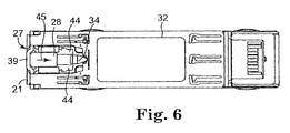
- actuator wedge 28 (seen in Figures 2, 5 and 6) is slidably retained in a slot (shown as T-slot 42) that is provided on surface 33.
- Slot 42 is configured to retain actuator wedge 28 such that wedge 28 can move toward and away from the front side 21 of transceiver module 10, but so that it cannot move laterally.
- the engaging shapes of actuator wedge 28 and slot 42 may differ from the T-shape illustrated, so long as slot 42 retains actuator wedge 28 adjacent surface 33 and permits wedge 28 to move toward and away from the front side 21 of transceiver module 10, but constrains lateral movement of actuator wedge 28.
- Actuator wedge 28 includes tines 44 spaced to accommodate latch boss 34 therebetween, such that when latch boss 34 is placed between tines 44, as illustrated in the Figures and described in greater detail below, linear movement of wedge 28 (in the direction of arrow 45 in Figure 6) will not be impeded by latch boss 34 as wedge 28 moves away from the front face 21 of transceiver module 10.
- Tines 44 of wedge 28 are configured with ramp portions 52. As wedge 28 moves away from the front face 21 of transceiver module 10, ramp portions 52 of tines 44 engage latch 16 of cage 12 and deflect latch 16 away from surface 33 of module 10.
- Ramp portions 52 are illustrated as having a generally linear slope, but can also be designed with non-linear slopes.
- cage latch 16 To extract transceiver module 10 from cage 12, cage latch 16 must be moved away from surface 33 of transceiver module 10 a sufficient distance so that that latch slot 40 is removed from engagement with latch boss 34 and latch boss 34 clears the front edge 36 of latch slot 40, as will be described more fully below.
- release handle 27 can be used to release transceiver module 10 from cage 12 so that it can be extracted therefrom.
- release handle 27 is shown in a closed or 0° position, such that it is generally parallel with the front face 21 of transceiver module 10.
- cam portion 39 of release handle 27 does not engage wedge 28 when release handle 27 is in the closed postion.
- cam portion 39 moves away from the front of transceiver module 10 with the rotation, thereby engaging actuator wedge 28 and causing actuator wedge 28 to move in an approximately linear direction within slot 42 away from the front face 21 of transceiver module 10 with the rotation of release handle 27.
- release tool 60 (illustrated in Figures 8A and 8B) can be used to release transceiver module 10 from cage 12 so that it can be extracted therefrom.
- Release tool 60 includes a handle portion 61 having connector engagement elements 62 at one end thereof. Engagement elements 62 are configured to engage receptacles 20 of transceiver module 10.
- Actuator arm 64 extends past connector engagement elements 62 and is shaped to approximately resemble wedge 28 at its distal end 66. Accordingly, similar reference numbers are used herein to designate similar parts.
- ramp portion(s) 52 engages latch 16 of cage 12 and deflect latch 16 away from surface 33 of module 10.
- actuator arm 64 is inserted through gap or opening 70 in front face 21 of housing 22. Opening 70 is sized to receive actuator arm 64 and permit actuator arm 64 to pass unimpeded through slot 42. From this first position, as removal tool 60 is advanced toward transceiver module 10, connector engagement elements 62 engage receptacles 20, and ramp portions 52 of actuator arm 64 engage cage latch 16. Ramp portion(s) 52 deflect latch 16 away from surface 33 of transceiver module 10 and consequently away from latch boss 34 to provide clearance for latch boss 34 to pass out of latch slot 40. Once actuator arm 64 of removal tool 60 is fully inserted and adequate clearance is provided, transceiver module 10 can be removed from cage 12, such as by pulling on handle portion 61 of removal tool 60.
- Actuator arm 64 of removal tool 60 is illustrated as spatially fixed with respect to handle portion 61 and connector engagement elements 62, such that connector engagement elements 62 engage receptacles 20 of transceiver module 10 concurrent with the engagement of actuator arm 64 and latch 16.
- actuator arm 64 may be movable with respect to handle portion 61 and connector engagement elements 62, such that connector engagement elements 62 engage receptacles 20 of transceiver module 10 prior to the engagement of actuator arm 64 and latch 16.
- Transceiver module 10 is generally small and only a small portion of transceiver module 10 is visible when installed in cage 12.
- Mode indicator button 30 ( Figures 2, 9A and 98) provides a highly visible color signal adjacent the front face 21 of transceiver module 10, and is visible from the front and top of transceiver module 10.
- Mode indicator button 30 is a molded plastic button (in any desired color) that is integral to the fiber optic input/output receptacles 20 of transceiver module 10, thereby clearly providing mode information to a user and adding no size to transceiver module 10.
- mode indicator button 30 includes a recessed portion 80 in its back surface that is shaped to receive protrusion 81 of housing 22. Mode indicator button 30 may be secured to protrusion 81 by means including press fit and adhesive. In another embodiment, the positions of recessed portion 80 and protrusion 81 may be switched such that mode indicator button 30 has a protrusion receivable in a recessed portion of housing 22.
- Mode indicator button 30 can be used to designate transceiver module 10 optical mode information, or in specific applications can be used by the end-user to designate user specific information.
- Mode indicator button 30 provides several advantages over previous color marking features, such as color coded molded handles. For example, mode indicator button is easily assembled for different mode configurations, adds no size to the transceiver module, and allows the use of either a handle 27 or a removal tool 60 to release the transceiver module 10 from cage 12. Previous color marking features, such as color coded molded handles, are obviously of no advantage in a transceiver module with no handle.
Landscapes
- Physics & Mathematics (AREA)
- General Physics & Mathematics (AREA)
- Optics & Photonics (AREA)
- Optical Couplings Of Light Guides (AREA)
Applications Claiming Priority (2)
| Application Number | Priority Date | Filing Date | Title |
|---|---|---|---|
| US758734 | 1996-11-18 | ||
| US10/758,734 US7625135B2 (en) | 2004-01-16 | 2004-01-16 | Dual configuration transceiver housing |
Publications (2)
| Publication Number | Publication Date |
|---|---|
| EP1555556A1 true EP1555556A1 (de) | 2005-07-20 |
| EP1555556B1 EP1555556B1 (de) | 2011-07-20 |
Family
ID=34620703
Family Applications (1)
| Application Number | Title | Priority Date | Filing Date |
|---|---|---|---|
| EP05075046A Ceased EP1555556B1 (de) | 2004-01-16 | 2005-01-06 | Zweifach einstellbares Sender-Empfänger Gehäuse |
Country Status (2)
| Country | Link |
|---|---|
| US (1) | US7625135B2 (de) |
| EP (1) | EP1555556B1 (de) |
Cited By (4)
| Publication number | Priority date | Publication date | Assignee | Title |
|---|---|---|---|---|
| WO2008003187A1 (en) * | 2006-06-29 | 2008-01-10 | Wuhan Telecommunication Devices Co., Ltd. | Unlocking device for opto-electronic module |
| US7766686B2 (en) | 2008-01-07 | 2010-08-03 | Applied Optoelectronics, Inc. | Pluggable form factor release mechanism |
| FR2945382A1 (fr) * | 2009-05-07 | 2010-11-12 | Mc Technology Gmbh | Dispositif pour detacher un emetteur-recepteur fixe dans un boitier |
| CN114252961A (zh) * | 2020-09-24 | 2022-03-29 | 美商祥茂光电科技股份有限公司 | 用于可插拔光次组件模组的锁合装置 |
Families Citing this family (12)
| Publication number | Priority date | Publication date | Assignee | Title |
|---|---|---|---|---|
| US8233796B2 (en) * | 2008-10-14 | 2012-07-31 | At&T Intellectual Property I, L. P. | Timing interface module with daughter timing reference modules |
| US20110206328A1 (en) * | 2010-02-25 | 2011-08-25 | Emcore Corporation | Optoelectronic module with emi shield |
| CN201708273U (zh) * | 2010-05-12 | 2011-01-12 | 富士康(昆山)电脑接插件有限公司 | 电连接器组件 |
| WO2013177234A1 (en) * | 2012-05-21 | 2013-11-28 | Advanced Fiber Products, LLC | Secure sc optical fiber connector and removal tools |
| US9104897B2 (en) | 2013-02-01 | 2015-08-11 | International Business Machines Corporation | Transceiver locking assembly |
| US9430004B2 (en) * | 2013-09-27 | 2016-08-30 | Avago Technologies General Ip (Singapore) Pte. Ltd. | Pull tab with exchangeable identification marker for pluggable communications modules |
| EP3271763B1 (de) | 2015-07-30 | 2021-09-01 | Hewlett Packard Enterprise Development LP | Sende- und empfangsmodul |
| JP7052943B2 (ja) * | 2018-02-16 | 2022-04-12 | 住友電工デバイス・イノベーション株式会社 | 光トランシーバ |
| US10859779B1 (en) * | 2020-03-04 | 2020-12-08 | Ii-Vi Delaware Inc. | Pluggable transceiver retainer |
| US11340411B2 (en) | 2020-04-21 | 2022-05-24 | Ii-Vi Delaware, Inc. | Pluggable transceiver retainer |
| US11372177B2 (en) | 2020-04-21 | 2022-06-28 | Ii-Vi Delaware, Inc. | Pluggable transceiver retainer |
| CN112346182B (zh) * | 2020-12-10 | 2021-07-06 | 武汉电信器件有限公司 | 一种光模块 |
Citations (7)
| Publication number | Priority date | Publication date | Assignee | Title |
|---|---|---|---|---|
| US6430053B1 (en) | 2001-12-13 | 2002-08-06 | Stratos Lightwave | Pluggable transceiver module having rotatable release and removal lever with living hinge |
| US20030059167A1 (en) * | 2001-04-14 | 2003-03-27 | Chiu Liew C. | De-latching mechanisms for fiber optic modules |
| US20030142917A1 (en) | 2002-01-31 | 2003-07-31 | Merrick Stephen P. | Pull detach mechanism for fiber optic transceiver module |
| US20030156801A1 (en) * | 2002-02-20 | 2003-08-21 | Jenq-Yih Hwang | Optoelectrical transceiver module with de-latching mechanism |
| US20030194190A1 (en) * | 2002-04-12 | 2003-10-16 | Huang Nan Tsung | Optoelectrical transceiver module with releasing mechanism |
| US20030198025A1 (en) * | 2002-04-17 | 2003-10-23 | Optical Communication Products, Inc. | Pluggable optical transceiver with pivtoing release actuator |
| US20030214789A1 (en) | 2002-05-15 | 2003-11-20 | Raul Medina | Wire lever actuator mechanism for optical transceiver |
Family Cites Families (17)
| Publication number | Priority date | Publication date | Assignee | Title |
|---|---|---|---|---|
| US5901263A (en) * | 1997-09-12 | 1999-05-04 | International Business Machines Corporation | Hot pluggable module integrated lock/extraction tool |
| DE19843628C2 (de) * | 1998-09-23 | 2000-10-12 | Siemens Ag | Verbindungssystem |
| US6517382B2 (en) * | 1999-12-01 | 2003-02-11 | Tyco Electronics Corporation | Pluggable module and receptacle |
| US6926551B1 (en) | 2000-01-11 | 2005-08-09 | Infineon Technologies Ag | Pluggable transceiver latching mechanism |
| US6335869B1 (en) * | 2000-01-20 | 2002-01-01 | International Business Machines Corporation | Removable small form factor fiber optic transceiver module and electromagnetic radiation shield |
| US6612858B1 (en) * | 2000-11-03 | 2003-09-02 | Infineon Technologies Ag | Device for unlocking an electronic component that is insertible into a receiving device |
| US6570768B2 (en) * | 2000-11-30 | 2003-05-27 | Stratos Lightwave | Pluggable transceiver module with extended release and removal lever |
| US6533470B2 (en) * | 2001-03-16 | 2003-03-18 | Infineon Technologies North America Corp. | Single-piece cage for pluggable fiber optic transceiver |
| US6796715B2 (en) * | 2001-04-14 | 2004-09-28 | E20 Communications, Inc. | Fiber optic modules with pull-action de-latching mechanisms |
| US6994478B1 (en) * | 2001-04-14 | 2006-02-07 | Jds Uniphase Corporation | Modules having rotatable release and removal lever |
| US6494623B1 (en) * | 2001-08-09 | 2002-12-17 | Infineon Technologies Ag | Release mechanism for pluggable fiber optic transceiver |
| US6533603B1 (en) * | 2001-10-04 | 2003-03-18 | Finisar Corporation | Electronic module having an integrated latching mechanism |
| US6439918B1 (en) * | 2001-10-04 | 2002-08-27 | Finisar Corporation | Electronic module having an integrated latching mechanism |
| US6885560B2 (en) * | 2002-04-19 | 2005-04-26 | Optical Communication Products, Inc. | Pluggable optical transceiver with push-pull actuator handle |
| US6762940B2 (en) * | 2002-05-02 | 2004-07-13 | Optical Communications Products, Inc. | Pluggable optical transceiver with push-pull actuator release collar |
| US7114984B2 (en) * | 2002-12-04 | 2006-10-03 | Tyco Electronics Corporation | Lever style de-latch mechanism for pluggable electronic module |
| US6916196B2 (en) * | 2003-03-22 | 2005-07-12 | Tyco Electronics Corporation | Push button de-latch mechanism for pluggable electronic module |
-
2004
- 2004-01-16 US US10/758,734 patent/US7625135B2/en active Active
-
2005
- 2005-01-06 EP EP05075046A patent/EP1555556B1/de not_active Ceased
Patent Citations (7)
| Publication number | Priority date | Publication date | Assignee | Title |
|---|---|---|---|---|
| US20030059167A1 (en) * | 2001-04-14 | 2003-03-27 | Chiu Liew C. | De-latching mechanisms for fiber optic modules |
| US6430053B1 (en) | 2001-12-13 | 2002-08-06 | Stratos Lightwave | Pluggable transceiver module having rotatable release and removal lever with living hinge |
| US20030142917A1 (en) | 2002-01-31 | 2003-07-31 | Merrick Stephen P. | Pull detach mechanism for fiber optic transceiver module |
| US20030156801A1 (en) * | 2002-02-20 | 2003-08-21 | Jenq-Yih Hwang | Optoelectrical transceiver module with de-latching mechanism |
| US20030194190A1 (en) * | 2002-04-12 | 2003-10-16 | Huang Nan Tsung | Optoelectrical transceiver module with releasing mechanism |
| US20030198025A1 (en) * | 2002-04-17 | 2003-10-23 | Optical Communication Products, Inc. | Pluggable optical transceiver with pivtoing release actuator |
| US20030214789A1 (en) | 2002-05-15 | 2003-11-20 | Raul Medina | Wire lever actuator mechanism for optical transceiver |
Cited By (4)
| Publication number | Priority date | Publication date | Assignee | Title |
|---|---|---|---|---|
| WO2008003187A1 (en) * | 2006-06-29 | 2008-01-10 | Wuhan Telecommunication Devices Co., Ltd. | Unlocking device for opto-electronic module |
| US7766686B2 (en) | 2008-01-07 | 2010-08-03 | Applied Optoelectronics, Inc. | Pluggable form factor release mechanism |
| FR2945382A1 (fr) * | 2009-05-07 | 2010-11-12 | Mc Technology Gmbh | Dispositif pour detacher un emetteur-recepteur fixe dans un boitier |
| CN114252961A (zh) * | 2020-09-24 | 2022-03-29 | 美商祥茂光电科技股份有限公司 | 用于可插拔光次组件模组的锁合装置 |
Also Published As
| Publication number | Publication date |
|---|---|
| EP1555556B1 (de) | 2011-07-20 |
| US20050158051A1 (en) | 2005-07-21 |
| US7625135B2 (en) | 2009-12-01 |
Similar Documents
| Publication | Publication Date | Title |
|---|---|---|
| US6997622B2 (en) | Mode indicator for transceiver module | |
| US7625135B2 (en) | Dual configuration transceiver housing | |
| US7303336B2 (en) | Transceiver module | |
| US7212410B2 (en) | Actuator for small form-factor pluggable transceiver | |
| US20070117458A1 (en) | Pluggable module and cage | |
| US7066765B2 (en) | Shielding tabs for reduction of electromagnetic interference | |
| US8814229B2 (en) | Latching mechanism for an electronic module | |
| US6494623B1 (en) | Release mechanism for pluggable fiber optic transceiver | |
| US6430053B1 (en) | Pluggable transceiver module having rotatable release and removal lever with living hinge | |
| US6890206B2 (en) | Optical transceiver latch | |
| US6778399B2 (en) | Wire lever actuator mechanism for optical transceiver | |
| US7186134B2 (en) | Electronic modules having integrated lever-activated latching mechanisms | |
| JP4093862B2 (ja) | 光ファイバ・モジュールのラッチ外し機構 | |
| US6556445B2 (en) | Transceiver module with extended release lever | |
| US6570768B2 (en) | Pluggable transceiver module with extended release and removal lever | |
| US20040185696A1 (en) | Push button de-latch mechanism for pluggable electronic module | |
| US20050148223A1 (en) | Release mechanism for transceiver module assembly | |
| US6885560B2 (en) | Pluggable optical transceiver with push-pull actuator handle | |
| US8573862B2 (en) | Narrow, pluggable optical transceiver system | |
| US7429185B1 (en) | Plug-in module with latch mechanism | |
| US20030118293A1 (en) | Snap together optoelectronic module | |
| US7380995B2 (en) | Latching mechanism for pluggable transceiver | |
| US20130077919A1 (en) | Optical-electrical connector having a magnetic member | |
| US7108523B2 (en) | Pluggable transceiver with cover resilient member | |
| TWI389397B (zh) | 無殼可插式光電裝置 |
Legal Events
| Date | Code | Title | Description |
|---|---|---|---|
| PUAI | Public reference made under article 153(3) epc to a published international application that has entered the european phase |
Free format text: ORIGINAL CODE: 0009012 |
|
| AK | Designated contracting states |
Kind code of ref document: A1 Designated state(s): AT BE BG CH CY CZ DE DK EE ES FI FR GB GR HU IE IS IT LI LT LU MC NL PL PT RO SE SI SK TR |
|
| AX | Request for extension of the european patent |
Extension state: AL BA HR LV MK YU |
|
| 17P | Request for examination filed |
Effective date: 20050906 |
|
| AKX | Designation fees paid |
Designated state(s): DE FR GB |
|
| RAP1 | Party data changed (applicant data changed or rights of an application transferred) |
Owner name: FINISAR CORPORATION |
|
| 17Q | First examination report despatched |
Effective date: 20051223 |
|
| GRAP | Despatch of communication of intention to grant a patent |
Free format text: ORIGINAL CODE: EPIDOSNIGR1 |
|
| GRAS | Grant fee paid |
Free format text: ORIGINAL CODE: EPIDOSNIGR3 |
|
| GRAA | (expected) grant |
Free format text: ORIGINAL CODE: 0009210 |
|
| AK | Designated contracting states |
Kind code of ref document: B1 Designated state(s): DE FR GB |
|
| REG | Reference to a national code |
Ref country code: GB Ref legal event code: FG4D |
|
| REG | Reference to a national code |
Ref country code: DE Ref legal event code: R096 Ref document number: 602005029054 Country of ref document: DE Effective date: 20110908 |
|
| PLBE | No opposition filed within time limit |
Free format text: ORIGINAL CODE: 0009261 |
|
| STAA | Information on the status of an ep patent application or granted ep patent |
Free format text: STATUS: NO OPPOSITION FILED WITHIN TIME LIMIT |
|
| 26N | No opposition filed |
Effective date: 20120423 |
|
| REG | Reference to a national code |
Ref country code: DE Ref legal event code: R097 Ref document number: 602005029054 Country of ref document: DE Effective date: 20120423 |
|
| REG | Reference to a national code |
Ref country code: FR Ref legal event code: PLFP Year of fee payment: 11 |
|
| REG | Reference to a national code |
Ref country code: FR Ref legal event code: PLFP Year of fee payment: 12 |
|
| REG | Reference to a national code |
Ref country code: FR Ref legal event code: PLFP Year of fee payment: 13 |
|
| REG | Reference to a national code |
Ref country code: FR Ref legal event code: PLFP Year of fee payment: 14 |
|
| PGFP | Annual fee paid to national office [announced via postgrant information from national office to epo] |
Ref country code: FR Payment date: 20171221 Year of fee payment: 14 |
|
| PGFP | Annual fee paid to national office [announced via postgrant information from national office to epo] |
Ref country code: GB Payment date: 20171222 Year of fee payment: 14 |
|
| PGFP | Annual fee paid to national office [announced via postgrant information from national office to epo] |
Ref country code: DE Payment date: 20171218 Year of fee payment: 14 |
|
| REG | Reference to a national code |
Ref country code: DE Ref legal event code: R119 Ref document number: 602005029054 Country of ref document: DE |
|
| GBPC | Gb: european patent ceased through non-payment of renewal fee |
Effective date: 20190106 |
|
| PG25 | Lapsed in a contracting state [announced via postgrant information from national office to epo] |
Ref country code: DE Free format text: LAPSE BECAUSE OF NON-PAYMENT OF DUE FEES Effective date: 20190801 Ref country code: FR Free format text: LAPSE BECAUSE OF NON-PAYMENT OF DUE FEES Effective date: 20190131 |
|
| PG25 | Lapsed in a contracting state [announced via postgrant information from national office to epo] |
Ref country code: GB Free format text: LAPSE BECAUSE OF NON-PAYMENT OF DUE FEES Effective date: 20190106 |