EP1555545A1 - Mehrstrahlenbündellaserentfernungsmesser - Google Patents
Mehrstrahlenbündellaserentfernungsmesser Download PDFInfo
- Publication number
- EP1555545A1 EP1555545A1 EP05250264A EP05250264A EP1555545A1 EP 1555545 A1 EP1555545 A1 EP 1555545A1 EP 05250264 A EP05250264 A EP 05250264A EP 05250264 A EP05250264 A EP 05250264A EP 1555545 A1 EP1555545 A1 EP 1555545A1
- Authority
- EP
- European Patent Office
- Prior art keywords
- ground
- pulses
- airborne platform
- platform relative
- time
- Prior art date
- Legal status (The legal status is an assumption and is not a legal conclusion. Google has not performed a legal analysis and makes no representation as to the accuracy of the status listed.)
- Withdrawn
Links
Images


Classifications
-
- G—PHYSICS
- G01—MEASURING; TESTING
- G01S—RADIO DIRECTION-FINDING; RADIO NAVIGATION; DETERMINING DISTANCE OR VELOCITY BY USE OF RADIO WAVES; LOCATING OR PRESENCE-DETECTING BY USE OF THE REFLECTION OR RERADIATION OF RADIO WAVES; ANALOGOUS ARRANGEMENTS USING OTHER WAVES
- G01S17/00—Systems using the reflection or reradiation of electromagnetic waves other than radio waves, e.g. lidar systems
- G01S17/87—Combinations of systems using electromagnetic waves other than radio waves
- G01S17/875—Combinations of systems using electromagnetic waves other than radio waves for determining attitude
-
- G—PHYSICS
- G01—MEASURING; TESTING
- G01S—RADIO DIRECTION-FINDING; RADIO NAVIGATION; DETERMINING DISTANCE OR VELOCITY BY USE OF RADIO WAVES; LOCATING OR PRESENCE-DETECTING BY USE OF THE REFLECTION OR RERADIATION OF RADIO WAVES; ANALOGOUS ARRANGEMENTS USING OTHER WAVES
- G01S13/00—Systems using the reflection or reradiation of radio waves, e.g. radar systems; Analogous systems using reflection or reradiation of waves whose nature or wavelength is irrelevant or unspecified
- G01S13/87—Combinations of radar systems, e.g. primary radar and secondary radar
- G01S13/874—Combination of several systems for attitude determination
-
- G—PHYSICS
- G01—MEASURING; TESTING
- G01S—RADIO DIRECTION-FINDING; RADIO NAVIGATION; DETERMINING DISTANCE OR VELOCITY BY USE OF RADIO WAVES; LOCATING OR PRESENCE-DETECTING BY USE OF THE REFLECTION OR RERADIATION OF RADIO WAVES; ANALOGOUS ARRANGEMENTS USING OTHER WAVES
- G01S13/00—Systems using the reflection or reradiation of radio waves, e.g. radar systems; Analogous systems using reflection or reradiation of waves whose nature or wavelength is irrelevant or unspecified
- G01S13/88—Radar or analogous systems specially adapted for specific applications
- G01S13/882—Radar or analogous systems specially adapted for specific applications for altimeters
-
- G—PHYSICS
- G01—MEASURING; TESTING
- G01S—RADIO DIRECTION-FINDING; RADIO NAVIGATION; DETERMINING DISTANCE OR VELOCITY BY USE OF RADIO WAVES; LOCATING OR PRESENCE-DETECTING BY USE OF THE REFLECTION OR RERADIATION OF RADIO WAVES; ANALOGOUS ARRANGEMENTS USING OTHER WAVES
- G01S13/00—Systems using the reflection or reradiation of radio waves, e.g. radar systems; Analogous systems using reflection or reradiation of waves whose nature or wavelength is irrelevant or unspecified
- G01S13/88—Radar or analogous systems specially adapted for specific applications
- G01S13/93—Radar or analogous systems specially adapted for specific applications for anti-collision purposes
- G01S13/933—Radar or analogous systems specially adapted for specific applications for anti-collision purposes of aircraft or spacecraft
- G01S13/935—Radar or analogous systems specially adapted for specific applications for anti-collision purposes of aircraft or spacecraft for terrain-avoidance
-
- G—PHYSICS
- G01—MEASURING; TESTING
- G01S—RADIO DIRECTION-FINDING; RADIO NAVIGATION; DETERMINING DISTANCE OR VELOCITY BY USE OF RADIO WAVES; LOCATING OR PRESENCE-DETECTING BY USE OF THE REFLECTION OR RERADIATION OF RADIO WAVES; ANALOGOUS ARRANGEMENTS USING OTHER WAVES
- G01S17/00—Systems using the reflection or reradiation of electromagnetic waves other than radio waves, e.g. lidar systems
- G01S17/02—Systems using the reflection of electromagnetic waves other than radio waves
- G01S17/50—Systems of measurement based on relative movement of target
- G01S17/58—Velocity or trajectory determination systems; Sense-of-movement determination systems
-
- G—PHYSICS
- G01—MEASURING; TESTING
- G01S—RADIO DIRECTION-FINDING; RADIO NAVIGATION; DETERMINING DISTANCE OR VELOCITY BY USE OF RADIO WAVES; LOCATING OR PRESENCE-DETECTING BY USE OF THE REFLECTION OR RERADIATION OF RADIO WAVES; ANALOGOUS ARRANGEMENTS USING OTHER WAVES
- G01S17/00—Systems using the reflection or reradiation of electromagnetic waves other than radio waves, e.g. lidar systems
- G01S17/88—Lidar systems specially adapted for specific applications
-
- G—PHYSICS
- G01—MEASURING; TESTING
- G01S—RADIO DIRECTION-FINDING; RADIO NAVIGATION; DETERMINING DISTANCE OR VELOCITY BY USE OF RADIO WAVES; LOCATING OR PRESENCE-DETECTING BY USE OF THE REFLECTION OR RERADIATION OF RADIO WAVES; ANALOGOUS ARRANGEMENTS USING OTHER WAVES
- G01S17/00—Systems using the reflection or reradiation of electromagnetic waves other than radio waves, e.g. lidar systems
- G01S17/88—Lidar systems specially adapted for specific applications
- G01S17/93—Lidar systems specially adapted for specific applications for anti-collision purposes
- G01S17/933—Lidar systems specially adapted for specific applications for anti-collision purposes of aircraft or spacecraft
Definitions
- the present invention relates to a laser rangefinder and, in particular, it concerns a multi-beam laser rangefinder.
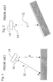
- Fig. 1 is a schematic view of a single-beam rangefinder 10 that is constructed and operable in accordance with the prior art.
- Single-beam rangefinder 10 is disposed on an airborne platform 14. Due to the orientation of airborne platform 14, the line of sight 12 of single-beam rangefinder 10 is directed to point A on the surface of the ground below. Therefore, single-beam rangefinder 10 measures a distance a from single-beam rangefmder 10 to the ground. However, the height of single-beam rangefinder 10 above the ground is equal to b.
- the altitude of airborne platform 14 is incorrectly measured.
- the accuracy of altitude calculation is very important.
- Fig. 2 is a schematic view of single-beam rangefinder 10 of Fig. 1 performing a measurement above sloped ground.
- line of sight 12 of single-beam rangefinder 10 is directed vertically downward.
- the ground below airborne platform 14 is sloped. Therefore, the altitude calculation measured by single-beam rangefinder 10 gives a false measurement of the position of airborne platform 14 relative to the ground below.
- the altitude calculation cannot be used to calculate roll or pitch of airborne platform 14 relative to the ground nor the time-to-hit the ground by airborne platform 14 for automatic landing purposes.
- the present invention is a multi-beam rangefinder system and method of operation thereof.
- a multi-beam rangefinder system for estimating a range-derived value of an airborne platform relative to the ground, the ground being approximated by a planar model
- the system comprising: (a) a transmitter arrangement configured for producing a plurality of pulses of electromagnetic radiation directed in at least three non-coplanar directions; (b) a sensor arrangement for sensing the pulses of electromagnetic radiation reflected from the ground; and (c) a processor arrangement configured for processing of independent measurements of time of flight of the pulses in each of the three non-coplanar directions in order to estimate the range derived value of the airborne platform relative to the ground.
- the transmitter arrangement is configured such that the pulses are produced as non-overlapping pulses.
- the transmitter arrangement is configured for producing the pulses sequentially in the three non-coplanar directions.
- the processor is configured for processing of independent measurements of time of flight of the pulses in each of the three non-coplanar directions in order to estimate an altitude of the airborne platform relative to the ground.
- the processor is configured for processing of independent measurements of time of flight of the pulses in each of the three non-coplanar directions in order to estimate a rate of a descent or ascent of the airborne platform relative to the ground.
- the processor is configured for processing of independent measurements of time of flight of the pulses in each of the three non-coplanar directions in order to estimate a rate of an acceleration of the airborne platform relative to the ground.
- the processor is configured for processing of independent measurements of time of flight of the pulses in each of the three non-coplanar directions in order to estimate a time to hit the ground by the airborne platform.
- the processor is configured for processing of independent measurements of time of flight of the pulses in each of the three non-coplanar directions in order to estimate a roll of the airborne platform relative to the ground.
- the processor is configured for processing of independent measurements of time of flight of the pulses in each of the three non-coplanar directions in order to estimate a pitch of the airborne platform relative to the ground.
- the processor is configured for processing of' independent measurements of time of flight of the pulses in each of the three non-coplanar directions in order to estimate an angular velocity of the airborne platform relative to the ground.
- the processor is configured for processing of independent measurements of time of flight of the pulses in each of the three non-coplanar directions in order to estimate an angular acceleration of the airborne platform relative to the ground.
- the sensor arrangement includes a single detector, the sensor arrangement having a field of view which is wide enough, such that the single detector detects the pulses of all of the at least three non-coplanar directions.
- an emergency system configured for being actuated in response to the range derived value exceeding a predefined value.
- the predefined value is a rate of a descent or ascent of the airborne platform relative to the ground.
- the predefined value is a time to hit the ground by the airborne platform.
- a method for estimating a range-derived value ofan airborne platform relative to the ground comprising the steps of: (a) producing a plurality of pulses of electromagnetic radiation directed in three non-coplanar directions; (b) receiving the pulses of electromagnetic radiation reflected from the ground; and (c) processing independent measurements of time of flight of the pulses in each of the three non-coplanar directions in order to estimate the range derived value of the airborne platform relative to the ground.
- the range defined value is a rate of a descent or ascent of the airborne platform relative to the ground.
- the range defined value is a time to hit the ground by the airborne platform.
- the range defined value is a roll of the airborne platform relative to the ground.
- the range defined value is a pitch of the airborne platform relative to the ground.
- the range defined value is an angular velocity of the airborne platform relative to the ground.
- the range defined value is an angular acceleration of the airborne platform relative to the ground.
- the range defined value is a rate of a descent or ascent of the airborne platform relative to the ground.
- the range defined value is an acceleration of the airborne platform relative to the ground.
- the step of producing is performed by producing the pulses as non-overlapping pulses directed in three non-coplanar directions.
- the step of producing is performed by producing the pulses sequentially in the three non-coplanar directions.
- the predefined value is a rate of a descent or ascent of the airborne platform relative to the ground.
- the predefined value is a time to hit the ground by the airborne platform.
- the present invention is a multi-beam rangefinder system and method of operation thereof.
- Multi-beam laser rangefinder system 16 is configured for estimating a range-derived value of an airborne platform 18 relative to the ground 20 .
- Multi-beam laser rangefinder system 16 performs time of flight calculations on directed laser pulses. These time of flights are typically, but not always, used to calculate the distance from the source of the laser pulses to the target of the laser pulses. Therefore, a range-derived value is defined herein as, any value that is determinable from the time of flight of the laser pulses and/or distance measurements performed by multi-beam laser rangefinder system 16.
- Multi-beam laser rangefinder system 16 estimates range-derived values by the following method.
- multi-beam laser rangefinder system 16 produces a plurality of pulses of electromagnetic radiation directed in three non-coplanar directions.
- the pulses are produced as non-overlapping pulses directed in the three non-coplanar directions as the pulses are detected by a single sensor, as will be described below with reference to Figs. 4 and 5.
- the term "produced as non-overlapping pulses" is defined herein as the pulses are produced one at a time and no two pulses are being produced by multi-beam laser rangefinder system 16 at the same time.
- multi-beam laser rangefinder system 16 is configured such that, a new pulse is not produced until an existing pulse has had time to reflect from the ground and be received by multi-beam laser rangefinder system 16 .
- Multi-beam laser rangefinder system 16 is generally configured such that the pulses are produced sequentially in the three non-coplanar directions. For example, one pulse is directed in a first direction, then a second pulse is directed in a second direction and a third pulse is then directed in a third direction. It will be appreciated by those ordinarily skilled in the art that other sequential patterns can be established.
- the pulses arrive at points B , C, and D on the ground. Points B, C and D define a plane BCD.
- the ground is approximated by a planar model passing through points B, C and D.
- the number of directions in which the pulses are directed can be increased.
- One of the advantages in increasing the number of directions is explained later. If more than three directions are used, only three of the directions need to be non-coplanar. For example, if four directions are used, three of the directions can define a plane.
- the term "in three non-coplanar directions" is defined herein to include more than three directions as long as a minimum of three of the directions chosen are non-coplanar.
- the pulses are reflected by the ground and received by multi-beam laser rangefinder system 16.
- Multi-beam laser rangefinder system 16 then processes independent measurements of time of flight of the pulses in each of the three non-coplanar directions in order to estimate range derived values of the airborne platform relative to the ground.
- the position of multi-beam laser rangefinder system 16 in relation to airborne platform 18 is known. Additionally, the orientation of the non-coplanar directions of the pulses relative to multi-beam laser rangefinder system 16 is known. Therefore, many range-derived values are estimated using the measurements performed by multi-beam laser rangefinder system 16 , as will now be explained. It will be appreciated by those ordinarily skilled in the art that as the position of multi-beam laser rangefinder system 16 in relation to airborne platform 18 is known, the range-derived value can be estimated for any point of airborne platform 18.
- range-derived value of an airborne platform relative to the ground is defined herein as, a range derived value of any point of airborne platform relative to the ground. Additionally, the orientation and position of any point of airborne platform 18 relative to any point on the planar model of the ground is known.
- Multi-beam laser rangefinder system 16 processes the time of flight of the pulses in order to derive the distances from point A to points B , C and D, namely, R 1 , R 2 and R 3 respectively.
- the angles between lines AB , AC and AD are known, the length of a line perpendicular to plane BCD from plane BCD to multi-beam laser rangefinder system 16 is calculated using geometry or vector analysis, giving the altitude, H , of airborne platform 18 .
- Vector analysis of the measurements performed by multi-beam laser rangefinder system 16 is described in more detail with reference to Fig. 6.
- the time derivative of H is calculated to give a rate of descent or ascent of airborne platform 18 relative to the ground.
- the time derivative of H is calculated using changing values of H over time.
- the time to hit the ground by airborne platform 18 is calculated, in the case of zero acceleration, by dividing H by the rate of a descent.
- the time to hit the ground by airborne platform 18, is calculated by solving a quadratic equation, for example, equation 19 below.
- the roll and pitch of airborne platform 18 relative to the ground are calculated by performing calculations using R 1 , R 2 and R 3 .
- the angular velocity and angular acceleration of airborne platform 18 relative to the ground are calculated from time derivatives of the roll and pitch or by performing calculations on the time derivatives of R 1 , R 2 and R 3 .
- the above range-derived values can be derived using other analytical and/or mathematical techniques.
- many other spatial and/or temporal values can be calculated from the measurements performed by multi-beam laser rangefinder system 16 .
- the number of non-coplanar directions that the pulses are directed in can be increased in order to increase the accuracy of the calculated range-derived values. Three non-coplanar directions is the minimum number required to calculate the range-derived values. If more than three non-coplanar directions are used, the error of the computations is decreased by averaging the results of successive computations derived for each group of three non-coplanar directions.
- the estimated range-derived values are used to give a pilot accurate information about the position, orientation and motion of airborne platform 18 .
- the estimated range derived values are also used for autopilot or autolanding of airborne platform 18 .
- the estimated range derived values, especially rate of a descent of airborne platform 18 and time-to-hit the ground are used to actuate an emergency system 22 when one or a combination of certain range derived values exceed predefined values.
- the term "exceed" is herein defined as, going beyond a predefined value either from above or below the predefined value. For example, when the time-to-hit falls below a predefined value, emergency system 22 is actuated and when the rate of descent climbs above a predefined value, emergency system 22 is actuated.
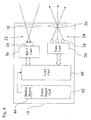
- Fig. 4 is a schematic block view of multi-beam laser rangefinder system 16 of Fig. 3.
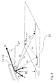
- Fig. 5 is a schematic isometric view of multi-beam laser rangefinder system 16 of Fig. 4 performing measurements.
- Multi-beam laser rangefinder system 16 includes a transmitter arrangement 24 configured for producing a plurality of pulses of electromagnetic radiation directed in at least three non-coplanar directions.
- Transmitter arrangement 24 has a transmitter card 26 , three laser diodes 28 and an optical arrangement 30 . It will be appreciated by those ordinarily skilled in the art that other laser sources can be used instead of laser diodes 28 .
- transmitter arrangement 24 can have more than three laser diodes to increase the number of directions that pulses are directed to, as described above with reference to Fig. 3.
- Transmitter card 26 manages the operation of laser diodes 28 including the timing of firing of the diodes and the duration of the pulses.
- the pulse repetition rate is typically in the range of 100 to 10,000 pulses per second and the pulse width is typically in the range of 10 to 50 nanoseconds.
- Transmitter card 26 is also configured such that, the pulses are non-overlapping pulses as described above with reference to Fig. 3.
- Transmitter card 26 is also configured for producing the pulses sequentially in the three non-coplanar directions, as described above with reference to Fig. 3.
- Laser diodes 28 are oriented such that, each laser diode 28 produces a pulse in one of the three non-coplanar directions.
- Optical arrangement 30 typically includes one or more lenses for focusing the light produced by the laser diodes 28.
- Multi-beam laser rangefinder system 16 also includes a sensor arrangement 32 for sensing the pulses of electromagnetic radiation reflected from the ground. Sensor arrangement 32 has a single detector 34 for detecting light pulses received from all three non-coplanar directions.
- Sensor arrangement 32 also includes a receiver card 36 and an optical arrangement 38.
- Optical arrangement 38 includes one or more lenses. Incoming laser pulses pass through optical arrangement 38 and arrive at detector 34 .
- Multi-beam laser rangefinder system 16 also includes a processor arrangement 40.
- Processor arrangement 40 is configured for calculating the time of flight of the pulses.
- Processor arrangement 40 manages the timing of the pulses. The timing is reset each time a pulse is produced to insure unambiguous measurement of elapsed time between laser emission and detection.
- Processor arrangement 40 is also configured for processing the independent measurements of time of flight of the pulses in each of the three non-coplanar directions in order to estimate range derived values of airborne platform 18 relative to the ground. As described with reference to Fig.
- multi-beam laser rangefinder system 16 is configured to estimate range derived values including, but not limited to, an altitude of airborne platform 18 relative to the ground, a rate of a descent or ascent of airborne platform 18 relative to the ground, a time to hit the ground by airborne platform 18, a roll and pitch of airborne platform 18 relative to the ground and an angular velocity and angular acceleration of airborne platform 18 relative to the ground.
- Multi-beam laser rangefinder system 16 also includes a power supply 42 and a backup battery 44 . It will be appreciated by those ordinarily skilled in the art that components and/or skills used for single-beam laser rangefinders can be used to produce multi-beam laser rangefinder system 16 .
- semiconductor lasers and detectors are generally suitable.
- Semiconductor GaAs lasers are commercially available from Perkin-Elmer, Inc. of 44370 Christy Street, Fremont, CA 94538-3180, USA and Laser Devices, Inc. of 2 Harris Court, Suite A-4, Monterey, California 93940, USA.
- Semiconductor Si or InGaAs detectors are commercially available from Perkin Elmer, Inc. and Analog Modules, Inc. of 126 Baywood Avenue Longwood, FL 32750-3426, USA.
- Suitable processors and controllers are commercially available from Analog Devices, Inc. of One Technology Way, P.O. Box 9106, Norwood, MA 02062-9106, USA and Texas Instruments, Inc. of 12500 TI Boulevard, Dallas, TX 75243-4136, USA.
- multi-beam laser rangefinder system 16 is constructed with a transmitter arrangement 24 including a plurality of narrow-beam lasers 28 with one wide field of view detector 34, so also a multi-beam laser rangefinder of the present invention can be constructed having a plurality of narrow field-of-view detectors and a single wide divergence laser. In both embodiments, the output is the range along a plurality of non-coplanar directions.
- the embodiment of multi-beam laser rangefinder system 16 requires less components and is more power efficient and accurate.
- Fig. 6 is a vector diagram, constructed using measurements performed by multi-beam laser rangefinder system 16 of Fig. 3.
- a right-hand coordinate system is attached to airborne platform 18, such that X direction is the forward axis of' airborne platform 18 , Y direction is perpendicular to X, and Z is perpendicular to X and Y.
- X direction is the forward axis of' airborne platform 18
- Y direction is perpendicular to X
- Z is perpendicular to X and Y.
- the unit vectors for each range measurement are defined as follows:
- Points x i , y i , z i are computed from the ranges R i , multiplied by the respective unit vectors, as follows:
- vector L normal L 21 ⁇ L 31
- the pitch angle ⁇ of airborne platform 18 is computed as follows (atan is the inverse of the trigonometric function tangent, sometimes denoted as tan -1 or tg -1 ):
- the roll angle ⁇ of airborne platform 18 is computed as follows:
- rate descent d ( H ) dt
- Time - rate descent + rate 2 descent +2 ⁇ accel ⁇ H accel
- Filtering techniques may be applied to the measurements to improve the accuracy of the computed values.
Landscapes
- Physics & Mathematics (AREA)
- Electromagnetism (AREA)
- Engineering & Computer Science (AREA)
- Computer Networks & Wireless Communication (AREA)
- General Physics & Mathematics (AREA)
- Radar, Positioning & Navigation (AREA)
- Remote Sensing (AREA)
- Optical Radar Systems And Details Thereof (AREA)
Applications Claiming Priority (2)
| Application Number | Priority Date | Filing Date | Title |
|---|---|---|---|
| IL15994504 | 2004-01-19 | ||
| IL15994504 | 2004-01-19 |
Publications (1)
| Publication Number | Publication Date |
|---|---|
| EP1555545A1 true EP1555545A1 (de) | 2005-07-20 |
Family
ID=34611181
Family Applications (1)
| Application Number | Title | Priority Date | Filing Date |
|---|---|---|---|
| EP05250264A Withdrawn EP1555545A1 (de) | 2004-01-19 | 2005-01-19 | Mehrstrahlenbündellaserentfernungsmesser |
Country Status (2)
| Country | Link |
|---|---|
| US (1) | US20050174560A1 (de) |
| EP (1) | EP1555545A1 (de) |
Cited By (12)
| Publication number | Priority date | Publication date | Assignee | Title |
|---|---|---|---|---|
| FR2888945A1 (fr) * | 2005-07-22 | 2007-01-26 | Johnson Controls Tech Co | Dispositif de detection au moyen de faisceaux croises du franchissement d'une ligne delimitant une voie de circulation sur une surface |
| WO2009123676A1 (en) * | 2008-04-02 | 2009-10-08 | Eastman Kodak Company | Distance and orientation measurement of an object |
| ITUD20080243A1 (it) * | 2008-11-17 | 2010-05-18 | Helica S R L | "metodo di rilevamento aereo tramite lidar" |
| WO2010071502A1 (en) * | 2008-12-15 | 2010-06-24 | Saab Ab | Measuring of a landing platform of a ship |
| WO2010144014A1 (en) * | 2009-06-12 | 2010-12-16 | Saab Ab | Centering above a predetermined area of a landing platform |
| US8554395B2 (en) | 2008-12-15 | 2013-10-08 | Saab Ab | Method and system for facilitating autonomous landing of aerial vehicles on a surface |
| US8855816B2 (en) | 2011-06-10 | 2014-10-07 | Seiko Epson Corporation | Piezoelectric actuator, robot hand, and robot |
| CN104251994A (zh) * | 2014-09-11 | 2014-12-31 | 上海卫星工程研究所 | 长基线激光测距实现无控制点卫星精确定位系统及方法 |
| EP1906151B1 (de) * | 2006-09-29 | 2016-12-14 | Applied Minds, Inc. | Abbildungs- und Anzeigesystem zur Unterstützung von Hubschrauberlandungen unter Brownout-Bedingungen |
| WO2019186172A1 (en) * | 2018-03-28 | 2019-10-03 | Psionic Llc | Navigation apparatus and method |
| EP3677929A1 (de) * | 2019-01-07 | 2020-07-08 | Commissariat à l'Energie Atomique et aux Energies Alternatives | Vorrichtung zum schätzen des geschwindigkeitsvektors eines bewegbaren starren körpers |
| AU2021204561A1 (en) * | 2021-06-30 | 2023-02-09 | Psionic Llc | Navigation system for gps denied environments |
Families Citing this family (10)
| Publication number | Priority date | Publication date | Assignee | Title |
|---|---|---|---|---|
| US7639346B2 (en) * | 2005-09-14 | 2009-12-29 | Booker Jr Reginald Earl | Non-contact measurement device |
| WO2011078838A1 (en) * | 2009-12-23 | 2011-06-30 | Booker Reginald Earl Jr | Non-contact measurement device |
| US9879995B2 (en) | 2012-09-13 | 2018-01-30 | Laser Technology, Inc. | System and method for superimposing a virtual aiming mechanism with a projected system beam in a compact laser-based rangefinding instrument |
| US9354051B2 (en) * | 2012-09-13 | 2016-05-31 | Laser Technology, Inc. | System and method for a rangefinding instrument incorporating pulse and continuous wave signal generating and processing techniques for increased distance measurement accuracy |
| US9213101B2 (en) | 2012-09-13 | 2015-12-15 | Laser Technology, Inc. | Self-aligned aiming system and technique for a laser rangefinder incorporating a retroreflector |
| US9897690B2 (en) | 2014-10-27 | 2018-02-20 | Laser Technology, Inc. | Technique for a pulse/phase based laser rangefinder utilizing a single photodiode in conjunction with separate pulse and phase receiver circuits |
| CN106896828B (zh) * | 2017-04-18 | 2019-09-06 | 厦门领夏智能科技有限公司 | 一种无人机自动无线充电方法及系统 |
| CN109581360B (zh) * | 2017-09-29 | 2023-06-02 | 英飞凌科技股份有限公司 | 用于光检测和测距的装置和方法 |
| CN108759792B (zh) * | 2018-08-24 | 2023-08-25 | 张洋 | 基于十字激光的无人机姿态与飞行高度的测量方法 |
| CN116819547A (zh) * | 2023-02-27 | 2023-09-29 | 中国人民解放军93209部队 | 一种多波长多波束激光测距方法 |
Citations (4)
| Publication number | Priority date | Publication date | Assignee | Title |
|---|---|---|---|---|
| US4023171A (en) * | 1975-11-12 | 1977-05-10 | The Singer Company | Microwave velocity sensor using altimeter echo |
| WO1998057192A1 (en) * | 1997-06-10 | 1998-12-17 | Honeywell Inc. | Altitude and velocity sensing system |
| US6064330A (en) * | 1997-01-28 | 2000-05-16 | Laser Technology, Inc. | Fog piercing ranging apparatus and method |
| US20030030582A1 (en) * | 2001-08-10 | 2003-02-13 | Vickers Roger S. | Environment measurement methods, systems, media, signals and data structures |
Family Cites Families (4)
| Publication number | Priority date | Publication date | Assignee | Title |
|---|---|---|---|---|
| US6683556B2 (en) * | 2000-10-10 | 2004-01-27 | Sandel Avionics, Inc. | Method and apparatus for predictive altitude display |
| US6593875B2 (en) * | 2001-06-29 | 2003-07-15 | Information Systems Laboratories, Inc. | Site-specific doppler navigation system for back-up and verification of GPS |
| US6950056B2 (en) * | 2002-05-13 | 2005-09-27 | Honeywell International Inc. | Methods and apparatus for determination of a filter center frequency |
| US20040107028A1 (en) * | 2002-12-03 | 2004-06-03 | Catalano Anthony B. | Override protocol system for affording vehicle safety and for preventing hijacking |
-
2005
- 2005-01-19 US US11/037,362 patent/US20050174560A1/en not_active Abandoned
- 2005-01-19 EP EP05250264A patent/EP1555545A1/de not_active Withdrawn
Patent Citations (4)
| Publication number | Priority date | Publication date | Assignee | Title |
|---|---|---|---|---|
| US4023171A (en) * | 1975-11-12 | 1977-05-10 | The Singer Company | Microwave velocity sensor using altimeter echo |
| US6064330A (en) * | 1997-01-28 | 2000-05-16 | Laser Technology, Inc. | Fog piercing ranging apparatus and method |
| WO1998057192A1 (en) * | 1997-06-10 | 1998-12-17 | Honeywell Inc. | Altitude and velocity sensing system |
| US20030030582A1 (en) * | 2001-08-10 | 2003-02-13 | Vickers Roger S. | Environment measurement methods, systems, media, signals and data structures |
Cited By (20)
| Publication number | Priority date | Publication date | Assignee | Title |
|---|---|---|---|---|
| WO2007009815A3 (fr) * | 2005-07-22 | 2007-04-26 | Johnson Controls Tech Co | Dispositif de detection au moyen de faisceaux croises du franchissement d’une ligne delimitant une voie de circulation sur une surface |
| FR2888945A1 (fr) * | 2005-07-22 | 2007-01-26 | Johnson Controls Tech Co | Dispositif de detection au moyen de faisceaux croises du franchissement d'une ligne delimitant une voie de circulation sur une surface |
| EP1906151B1 (de) * | 2006-09-29 | 2016-12-14 | Applied Minds, Inc. | Abbildungs- und Anzeigesystem zur Unterstützung von Hubschrauberlandungen unter Brownout-Bedingungen |
| WO2009123676A1 (en) * | 2008-04-02 | 2009-10-08 | Eastman Kodak Company | Distance and orientation measurement of an object |
| CN101981468B (zh) * | 2008-04-02 | 2013-03-27 | 伊斯曼柯达公司 | 物体的距离和取向测量 |
| ITUD20080243A1 (it) * | 2008-11-17 | 2010-05-18 | Helica S R L | "metodo di rilevamento aereo tramite lidar" |
| EP2366130A4 (de) * | 2008-12-15 | 2014-11-12 | Saab Ab | Messung einer landeplattform eines schiffs |
| WO2010071502A1 (en) * | 2008-12-15 | 2010-06-24 | Saab Ab | Measuring of a landing platform of a ship |
| US8457813B2 (en) | 2008-12-15 | 2013-06-04 | Saab Ab | Measuring of a landing platform of a ship |
| US8554395B2 (en) | 2008-12-15 | 2013-10-08 | Saab Ab | Method and system for facilitating autonomous landing of aerial vehicles on a surface |
| WO2010144014A1 (en) * | 2009-06-12 | 2010-12-16 | Saab Ab | Centering above a predetermined area of a landing platform |
| US9158306B2 (en) | 2009-06-12 | 2015-10-13 | Saab Ab | Centering above a predetermined area of a landing platform |
| EP2440982A4 (de) * | 2009-06-12 | 2016-08-10 | Saab Ab | Zentrierung über einem vordefinierten bereich einer landefläche |
| US8855816B2 (en) | 2011-06-10 | 2014-10-07 | Seiko Epson Corporation | Piezoelectric actuator, robot hand, and robot |
| CN104251994A (zh) * | 2014-09-11 | 2014-12-31 | 上海卫星工程研究所 | 长基线激光测距实现无控制点卫星精确定位系统及方法 |
| WO2019186172A1 (en) * | 2018-03-28 | 2019-10-03 | Psionic Llc | Navigation apparatus and method |
| US10935670B2 (en) | 2018-03-28 | 2021-03-02 | Psionic, Llc | Navigation system for GPS denied environments |
| EP3677929A1 (de) * | 2019-01-07 | 2020-07-08 | Commissariat à l'Energie Atomique et aux Energies Alternatives | Vorrichtung zum schätzen des geschwindigkeitsvektors eines bewegbaren starren körpers |
| FR3091591A1 (fr) * | 2019-01-07 | 2020-07-10 | Commissariat A L'energie Atomique Et Aux Energies Alternatives | Dispositif d’estimation du vecteur vitesse d’un corps rigide mobile |
| AU2021204561A1 (en) * | 2021-06-30 | 2023-02-09 | Psionic Llc | Navigation system for gps denied environments |
Also Published As
| Publication number | Publication date |
|---|---|
| US20050174560A1 (en) | 2005-08-11 |
Similar Documents
| Publication | Publication Date | Title |
|---|---|---|
| US20050174560A1 (en) | Multi-beam laser rangefinder | |
| EP2366130B1 (de) | Messung einer schiffslandeplattform | |
| US7859449B1 (en) | System and method for a terrain database and/or position validation | |
| US6590520B1 (en) | Method and system for determining air turbulence using bi-static measurements | |
| US10175359B2 (en) | Atmospheric turbulence data optical system | |
| US8081106B2 (en) | Target ranging using information from two objects | |
| US9008869B2 (en) | Low-altitude altimeter and method | |
| Vaman | TRN history, trends and the unused potential | |
| EP1200800B1 (de) | Bodennavigationsgeraet | |
| EP3699645B1 (de) | Systeme und verfahren zur fahrzeugnavigation | |
| US9341705B2 (en) | Passive ranging of a target | |
| US20030102999A1 (en) | Site-specific doppler navigation system for back-up and verification of gps | |
| EP2084636B1 (de) | System und verfahren zur zielverfolgung | |
| Amzajerdian et al. | Doppler lidar sensor for precision landing on the moon and mars | |
| JP2009510487A5 (de) | ||
| US7149648B1 (en) | System and method for relative positioning of an autonomous vehicle | |
| Johnson et al. | Analysis and testing of a lidar-based approach to terrain relative navigation for precise lunar landing | |
| US7792330B1 (en) | System and method for determining range in response to image data | |
| Kikuchi et al. | Real-time estimation of airflow vector based on lidar observations for preview control | |
| US20240219557A1 (en) | MOVING APERTURE LiDAR | |
| CN116002078A (zh) | 一种非合作目标全自主防撞规避方法 | |
| EP0820040B1 (de) | Passive Entfernungsabschätzung unter Verwendung von Bildgrösseabmessungen | |
| US10670396B2 (en) | Multi-sensor target location registration | |
| Xu et al. | Uncertainty aware EKF: a tracking filter learning LiDAR measurement uncertainty | |
| Vacek et al. | Single photon laser altimeter data processing, analysis and experimental validation |
Legal Events
| Date | Code | Title | Description |
|---|---|---|---|
| PUAI | Public reference made under article 153(3) epc to a published international application that has entered the european phase |
Free format text: ORIGINAL CODE: 0009012 |
|
| AK | Designated contracting states |
Kind code of ref document: A1 Designated state(s): AT BE BG CH CY CZ DE DK EE ES FI FR GB GR HU IE IS IT LI LT LU MC NL PL PT RO SE SI SK TR |
|
| AX | Request for extension of the european patent |
Extension state: AL BA HR LV MK YU |
|
| 17P | Request for examination filed |
Effective date: 20060116 |
|
| AKX | Designation fees paid |
Designated state(s): AT BE BG CH CY CZ DE DK EE ES FI FR GB GR HU IE IS IT LI LT LU MC NL PL PT RO SE SI SK TR |
|
| 17Q | First examination report despatched |
Effective date: 20080922 |
|
| STAA | Information on the status of an ep patent application or granted ep patent |
Free format text: STATUS: THE APPLICATION IS DEEMED TO BE WITHDRAWN |
|
| 18D | Application deemed to be withdrawn |
Effective date: 20080801 |