EP1555525A1 - Oxygen sensor and method of producing same - Google Patents
Oxygen sensor and method of producing same Download PDFInfo
- Publication number
- EP1555525A1 EP1555525A1 EP04029176A EP04029176A EP1555525A1 EP 1555525 A1 EP1555525 A1 EP 1555525A1 EP 04029176 A EP04029176 A EP 04029176A EP 04029176 A EP04029176 A EP 04029176A EP 1555525 A1 EP1555525 A1 EP 1555525A1
- Authority
- EP
- European Patent Office
- Prior art keywords
- layer
- printed
- base member
- oxygen
- detecting
- Prior art date
- Legal status (The legal status is an assumption and is not a legal conclusion. Google has not performed a legal analysis and makes no representation as to the accuracy of the status listed.)
- Withdrawn
Links
Images


Classifications
-
- B—PERFORMING OPERATIONS; TRANSPORTING
- B05—SPRAYING OR ATOMISING IN GENERAL; APPLYING FLUENT MATERIALS TO SURFACES, IN GENERAL
- B05B—SPRAYING APPARATUS; ATOMISING APPARATUS; NOZZLES
- B05B1/00—Nozzles, spray heads or other outlets, with or without auxiliary devices such as valves, heating means
- B05B1/30—Nozzles, spray heads or other outlets, with or without auxiliary devices such as valves, heating means designed to control volume of flow, e.g. with adjustable passages
- B05B1/3026—Gate valves; Sliding valves; Cocks
-
- G—PHYSICS
- G01—MEASURING; TESTING
- G01N—INVESTIGATING OR ANALYSING MATERIALS BY DETERMINING THEIR CHEMICAL OR PHYSICAL PROPERTIES
- G01N27/00—Investigating or analysing materials by the use of electric, electrochemical, or magnetic means
- G01N27/26—Investigating or analysing materials by the use of electric, electrochemical, or magnetic means by investigating electrochemical variables; by using electrolysis or electrophoresis
- G01N27/403—Cells and electrode assemblies
- G01N27/406—Cells and probes with solid electrolytes
- G01N27/407—Cells and probes with solid electrolytes for investigating or analysing gases
- G01N27/4071—Cells and probes with solid electrolytes for investigating or analysing gases using sensor elements of laminated structure
-
- B—PERFORMING OPERATIONS; TRANSPORTING
- B05—SPRAYING OR ATOMISING IN GENERAL; APPLYING FLUENT MATERIALS TO SURFACES, IN GENERAL
- B05B—SPRAYING APPARATUS; ATOMISING APPARATUS; NOZZLES
- B05B12/00—Arrangements for controlling delivery; Arrangements for controlling the spray area
- B05B12/002—Manually-actuated controlling means, e.g. push buttons, levers or triggers
-
- B—PERFORMING OPERATIONS; TRANSPORTING
- B08—CLEANING
- B08B—CLEANING IN GENERAL; PREVENTION OF FOULING IN GENERAL
- B08B5/00—Cleaning by methods involving the use of air flow or gas flow
- B08B5/02—Cleaning by the force of jets, e.g. blowing-out cavities
Definitions
- the present invention relates in general to an oxygen sensor and a method of producing the same and more specifically, to an oxygen concentration detecting element for the oxygen sensor and a method of producing same.
- the oxygen sensor has an oxygen concentration detecting element installed therein.
- oxygen concentration detecting element 100 comprises a cylindrical center rod 110 that serves as a structural base, a heater pattern 111 that is disposed (or printed) on and about an outer surface of cylindrical center rod 110, a heater insulating layer 112 that is lined on the outer surface of cylindrical center rod 110 while covering heater pattern 111, a porous layer 103 that is formed on an outer surface of insulating layer 112, a reference electrode layer 104 that is disposed on and about a part of porous layer 103, a solid electrolyte layer 102 that is disposed on and about porous layer 103 while covering reference electrode layer 104, a detecting electrode layer 105 that is disposed on solid electrolyte layer 102, a dense layer 106 that covers entirely outer surfaces of detecting electrode layer 105 and solid electrolyte layer 102 except an oxygen gas introduction part 106a exposed to the outer surface of detecting electrode layer 105, and a protecting layer
- Reference electrode layer 104 and detecting electrode layer 105 are both constructed of an electrically conductive material through which oxygen gas can permeate.
- the two electrode layers 104 and 105 have respective lead line portions. Only lead line portion 113 for detecting electrode layer 105 is shown. That is, by connecting these line portions 113 to a voltage meter (not shown), an output voltage appearing between reference electrode layer 104 and detecting electrode layer 105 is measured.
- solid electrolyte layer 102 and the above-mentioned two electrode layers 104 and 105 constitute an oxygen detecting portion 120.
- Dense layer 106 is constructed of a material that does not permit penetration of oxygen gas therethrough.
- Protecting layer 107 is constructed of a material through which harmful gases in the exhaust gas can not permeate but oxygen gas can permeate.
- oxygen concentration detecting element 100 for production of oxygen concentration detecting element 100 of the above-mentioned type, paste materials for heater pattern 111, cylindrical insulating layer 112, reference electrode layer 104, solid electrolyte layer 102 and detecting electrode layer 105 are printed on the associated surfaces by means of a screen printing method and thereafter a green body thus produced is baked or sintered at a temperature of about 1400°C to 1500°C for a given time.
- Cylindrical center rod 110 is constructed of an electrically insulating material (for example, material including alumina as a major material), and solid electrolyte layer 102 is constructed of an oxygen ion conduction material (for example, material including zirconia as a major material) that conducts oxygen ion.
- cylindrical center rod 110 and solid electrolyte layer 102 show a different degree of contraction during and after the baking or sintering. This difference in contraction tends to cause production of undesired cracks of solid electrolyte layer 102.
- an oxygen concentration detecting element and a method of producing the same, which produce no cracks on a solid electrolyte layer even when a cylindrical base member and the solid electrolyte layer show different degree of contraction during and after the baking or sintering.
- an oxygen concentration detecting element which comprises a base member constructed of an insulating material; an electric heater layer attached to the base member to generate a heat when electrically energized; and an oxygen detecting laminated unit attached to the base member, the oxygen detecting laminated unit including a solid electrolyte layer and reference and detecting electrode layers between which the solid electrolyte layer is operatively sandwiched, wherein the thickness of the oxygen detecting laminated unit is equal to or smaller than 11% of the thickness of the base member.
- An oxygen concentration detecting element which comprises a cylindrical base member constructed of a ceramic material containing alumina; an electric heater layer attached to the base member to generate a heat when electrically energized, the heater layer being constructed of tungsten or platinum; and an oxygen detecting laminated unit attached to the base member, the oxygen detecting laminated unit including a solid electrolyte layer and reference and detecting electrode layers between which the solid electrolyte layer is operatively sandwiched, the solid electrolyte layer being constructed of a material containing zirconia and yttria, the reference and detecting electrode layers being constructed of a conductive material that includes platinum and allows oxygen gas to penetrate therethrough, wherein the thickness of the oxygen detecting laminated unit is equal to or smaller than 11% of the diameter of the cylindrical base member.
- a method of producing an oxygen concentration detecting element which comprises the steps of (a) rotating a cylindrical base member about its axis; (b) applying a paste material for a heater pattern onto a cylindrical outer surface of the cylindrical base member via a screen printing; (c) applying a paste material for a heater insulating layer onto an outer surface of the printed heater pattern via a screen printing; (d) applying a paste material for a stress damping layer onto the outer surface of the cylindrical base member via screen printing; (e) applying a paste material for a reference electrode layer onto an outer surface of the printed stress damping layer via screen printing; (f) applying a paste material for a solid electrolyte layer onto an outer surface of the printed reference electrode layer via screen printing; (g) applying a paste material for a detecting electrode layer onto an outer surface of the printed solid electrolyte layer via screen printing thereby constituting a green body of the oxygen concentration detecting element, the green body having a green part for an oxygen
- FIG. 1 there is shown in a sectional manner an oxygen concentration detecting element 1A which is the first embodiment of the present invention.
- oxygen concentration detecting element 1A comprises a cylindrical center rod (or base member) 2 that serves as a structural base, a heater pattern 3 that is disposed on a half zone of a cylindrical outer surface 2a of cylindrical center rod 2, a heater insulating layer 4 that covers entirely an outer surface of heater pattern 3, a solid electrolyte layer 5 that is disposed on outer surface 2a of cylindrical center rod 2 at a diametrically opposite zone of heater pattern 3, a reference electrode layer 6 that is disposed on an inner surface of solid electrolyte layer 5 and a detecting electrode layer 7 that is disposed on an outer surface of solid electrolyte layer 5, a stress damping layer 8 that is intimately disposed between the inner surface of reference electrode layer 6 and outer surface 2a of cylindrical center rod 2, a dense layer 9 that covers the outer surface of solid electrolyte layer 5 and covers detecting electrode layer 7, a rectangular window opening 9a that is defined by dense layer 9, a print protecting layer 10 that entirely covers dense layer 9 and heat insulating layer 4 and a spine
- Cylindrical center rod 2 is constructed of an insulating material, such as a ceramic material that includes alumina as the major material. As shown, center rod 2 is of a cylindrical solid member with the cylindrical outer surface 2a.
- Heater pattern 3 is constructed of a conductive material, such as tungsten, platinum or the like that generates heat when electrically energized. As will be seen from Fig. 2, heater pattern 3 is integrally formed with lead line portions 3a. That is, when electrically energized through lead line portions 3a, heater pattern 3 generates a heat for heating and thus activating solid electrolyte layer 5.
- heater insulating layer 4 is constructed of an insulating material and functions to insulate heater pattern 3 from the surrounding parts.
- Solid electrolyte layer 5 is constructed of a material that includes zirconia as a major material.
- a powder of zirconia and a given wt.% of powder of yttria are mixed and added with a predetermined liquid to prepare a paste material.
- the paste material is baked together with other laminated layers.
- Solid electrolyte layer 5 generates between reference and detecting layers 6 and 7 an electromotive force in accordance with a difference in oxygen concentration of surrounding atmosphere. That is, due to a difference in oxygen concentration, oxygen ions are moved in solid electrolyte layer 5 in the direction of the thickness of the layer 5.
- Solid electrolyte layer 5 and reference and detecting electrode layers 6 and 7 thus constitute an oxygen detecting laminated unit 15 that converts the detected oxygen concentration to a corresponding electric signal.
- the thickness of oxygen detecting laminated unit 15 is equal to or smaller than 11% of the diameter of cylindrical center rod 2.
- the diameter of the rod 2 is 5mm and the thickness of oxygen detecting laminated unit 15 is equal to or smaller than 560 ⁇ m.
- Both reference and detecting electrode layers 6 and 7 are constructed of a conductive material that includes platinum as a major material and allows oxygen gas to penetrate therethrough. As is seen from Fig. 2, reference and detecting electrode layers 6 and 7 are respectively formed with lead line portions 6a and 7a. That is, the output power produced between reference and detecting electrode layers 6 and 7 is led to a meter section (not shown) through lead line portions 6a and 7a.
- stress damping layer 8 is constructed of a material that contains zirconia and aluminum. Stress damping layer 8 functions to damp a stress difference that would be produced between solid electrolyte layer 5 and cylindrical center rod 2 during the baking or sintering of a green body of solid electrolyte layer 5. In addition to this function, stress damping layer 8 forms a gas escaping passage through which oxygen gas that has been transmitted to reference electrode layer 6 through solid electrolyte layer 5 is led to an escaping path (not shown).
- Dense layer 9 is constructed of a material, such as a ceramic material like alumina, that does not permit penetration of oxygen gas therethrough. Dense layer 9 entirely covers the outer surface of solid electrolyte layer 5. Detecting electrode layer 7 is exposed to rectangular window opening 9a of dense layer 9. That is, in use, oxygen gas is led to detecting electrode layer 7 through only the rectangular window opening 9a.
- Print protecting layer 10 covers an outer surface of detecting electrode layer 7 that is exposed to rectangular window opening 9a of dense layer 9.
- Print protecting layer 10 is constructed of a material that does not permit penetration of harmful gases, particles and dusts in the exhaust gas therethrough but permits penetration of oxygen gas therethrough.
- the material is for example a porous member that is produced from a mixture of an aluminum powder and a magnesium oxide powder.
- Spinel protecting layer 11 is constructed of a porous material that permits penetration of oxygen gas therethrough. Spinel protecting layer 11 is rougher in porosity than print protecting layer 10.
- Fig. 3 is an extend elevation of oxygen concentration detecting element 1A of the first embodiment, schematically showing the arrangement of essential parts of the detecting element 1A.
- cylindrical center rod 2 produced from a ceramic material via an injection molding is prepared.
- the ceramic material includes alumina as a major material.
- a paste material for heater pattern 3 is screen printed on a cylindrical half zone of outer surface 2a of cylindrical center rod 2 while rotating the rod 2.
- a conductive material is used for the material of heater pattern 3, which is tungsten, platinum or the like, that generates heat when electrically energized.
- a so-called thick-film printing method is employed.
- a paste material for heater insulating layer 4 is screen printed on the cylindrical half zone of outer surface 2a of the center rod 2 in a manner to entirely cover printed heater pattern 3.
- a paste material for stress damping layer 8 is screen printed on outer surface 2a of the center rod 2 at a diametrically opposite zone of the printed heater pattern 3 while rotating the center rod 2.
- printed reference electrode layer 6 contains platinum as the major material and has lead line portion 6a integrally formed therewith.
- a paste material for solid electrolyte layer 5 is screen printed on a part of the diametrically opposite zone of outer surface 2a of the center rod 2 while covering essential enlarged portions of both of printed stress damping layer 8 and printed reference electrode layer 6.
- the paste material for solid electrolyte layer 5 includes zirconia as a major material.
- a paste material for detecting electrode layer 7 is screen printed on a back surface of printed electrolyte layer 5.
- printed detecting electrode layer 7 contains platinum as the major material and has lead line portion 7a integrally formed therewith.
- the paste material for lead line portion 6a of reference electrode layer 6 and the paste material for lead line portion 7a of detecting electrode layer 7 are located at circumferentially different positions and thus the respective lead line portions 6a and 7a are electrically insulated from each other.
- a paste material for dense layer 9 is screen printed on the diametrically opposite zone of the center rod 2 while covering printed detecting electrode layer 7 and printed electrolyte layer 5 except a part of the printed detecting electrode layer 7.
- the paste material for dense layer 9 is formed with a rectangular window opening 9a to which a base portion of printed detecting electrode layer 7 is exposed.
- the paste material for dense layer 9 contains ceramic material like alumina. It is important to expose the base portion of detecting electrode layer 7 to rectangular window opening 9a.
- a paste material for print protecting layer 10 is screen printed almost entirely on and about the cylindrical outer surface of the center rod 2 while covering essential portions of the printed layers 3, 4, 8, 6, 5, 7 and 9 directly and indirectly.
- an opening of rectangular window opening 9a of dense layer 9 is also covered by the printed protecting layer 10.
- the paste material for print protecting layer 10 contains aluminum and magnesium oxide.
- a paste material for spinel protecting layer 11 is screen printed entirely on and about the cylindrical outer surface of the center rod 2 while covering the entire all portions of the printed layers 3, 4, 8, 6, 5, 7, 9 and 10 directly and indirectly.
- the screen printing steps are completed, and as a result, a so-called green body for the oxygen concentration detecting element 1A is produced.
- the green body is baked in a sintering furnace (not shown) at a temperature of 1400°C to 1500°C for a given time. With this baking step, the green body is sintered to form a finished product, that is, the oxygen concentration detecting element 1A.
- the detecting element 1A is set in a case of an oxygen sensor.
- the oxygen concentration detecting element 1A will be briefly described in case wherein the corresponding oxygen sensor is set in an exhaust pipe that extends from an internal combustion engine (not shown). That is, upon assembly, the outer surface of the detecting element 1A is exposed to the interior of the exhaust pipe through openings of the case of the oxygen sensor, and the stress damping layer 8 is communicated with the atmosphere.
- heater pattern 3 Upon operation of the engine, heater pattern 3 is energized to generate a heat for heating and thus activating solid electrolyte layer 5. With this, the oxygen concentration detecting ability of the detecting element 1A is increased.
- the exhaust gas from the engine passes by the outer surface of the detecting element 1A.
- oxygen in the exhaust gas is led to solid electrolyte layer 5 through spinel protecting layer 11, print protecting layer 10 and detecting electrode layer 7, and at the same time, oxygen in the atmosphere is collected around reference electrode layer 6.
- oxygen ions are moved in the electrolyte layer 5 thereby to produce an electromotive force between reference and detecting electrode layers 6 and 7.
- an output voltage is obtained, which varies in accordance with the oxygen concentration difference, like in the above-mentioned conventional case.
- cylindrical center rod 2 and oxygen detecting laminated unit 15 show a different degree of contraction, which brings about production of a certain stress applied thereto. It has been revealed that such stress increases with increase of rate of thickness of oxygen detecting lamintated unit 15 to thickness of cylindrical center rod 2.
- the thickness of oxygen detecting laminated unit 15 is equal to or smaller than 11% of that of cylindrical center rod 2, the stress produced as a result of the different degree of contraction can be controlled lower than 900Mpa that the solid electrolyte layer 5 can sufficiently bear.
- the thickness of oxygen detecting laminated unit 15 is equal to or smaller than 11% of that of cylindrical center rod 2, only the contraction stress of center rod 2 stands out. Furthermore, since the contraction of oxygen detecting laminated unit 15 is made only in the direction of the thickness of the same, that is, in the direction of the diameter of cylindrical center rod 2, solid electrolyte layer 5 of oxygen detecting laminated unit 15 is suppressed from having cracks and/or peelings.
- the center rod 2 has the cylindrical outer surface 2a, positioning and setting of the detecting element 1A relative to the exhaust pipe are easily made without worrying at the posture of the same relative to the flow of the exhaust gas. This brings about a stable operation of oxygen detecting element 1A.
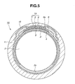
- FIG. 5 there is shown in a sectional manner an oxygen concentration detecting element 1B which is the second embodiment of the present invention.
- the detecting element 1B of this second embodiment is similar to the above-mentioned detecting element 1A of the first embodiment, only parts or portions that are different from those of the first embodiment 1A will be described in detail in the following description.
- the heater pattern 3' is arranged at the same zone as oxygen detecting laminated unit 15. More specifically, heater pattern 3' has an intermediate portion positioned in the vicinity of oxygen detecting laminated unit 15. In other words, heater pattern 3', heating insulating layer 4, stress damping layer 8 and oxygen detecting laminated unit 15 constitute a laminated structure.
- the thickness of oxygen detecting laminated unit 15 is equal to or smaller than 11 % of the diameter of cylindrical center rod 2, like in the above-mentioned first embodiment 1A. That is, the diameter of the rod 2 is 5mm and the thickness of oxygen detecting laminated unit 15 is smaller than 560 ⁇ m.
- cylindrical center rod 2 and oxygen detecting laminated unit 15 show a different degree of contraction, which brings about production of a certain stress applied thereto.
- Such stress increases with increase of rate of thickness of oxygen detecting laminated unit 15 to thickness of cylindrical center rod 2.
- the thickness of oxygen detecting laminated unit 15 is equal to or smaller than 11% of that of cylindrical center rod 2, the stress produced as a result of the different degree of contraction can be controlled lower than 900Mpa that the solid electrolyte layer 5 can sufficiently bear.
- the above-mentioned second, third and fourth advantages of the first embodiment 1A are equally achieved in the second embodiment 1B.
- the window opening 9a of dense layer 9 may be circular, elliptic or polygonal in shape, and the center rod 2 may be prismatic in shape.
Landscapes
- Chemical & Material Sciences (AREA)
- Life Sciences & Earth Sciences (AREA)
- Health & Medical Sciences (AREA)
- Physics & Mathematics (AREA)
- Chemical Kinetics & Catalysis (AREA)
- Electrochemistry (AREA)
- Molecular Biology (AREA)
- Analytical Chemistry (AREA)
- Biochemistry (AREA)
- General Health & Medical Sciences (AREA)
- General Physics & Mathematics (AREA)
- Immunology (AREA)
- Pathology (AREA)
- Measuring Oxygen Concentration In Cells (AREA)
Abstract
Description
- The present invention relates in general to an oxygen sensor and a method of producing the same and more specifically, to an oxygen concentration detecting element for the oxygen sensor and a method of producing same.
- In general, a modernized motor vehicle powered by an internal combustion engine is equipped at an exhaust pipe with an oxygen sensor for sensing the oxygen concentration in the exhaust gas from the engine, and based on the oxygen concentration thus sensed, the air/fuel mixture fed to the engine is feedback controlled to have a stoichiometric ratio (viz., A/F = 14.7).
- The oxygen sensor has an oxygen concentration detecting element installed therein.
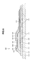
- In order to clarify the invention, an oxygen concentration detecting element disclosed in Japanese Laid-open Patent Application (Tokkaihei) 7-27737 will be briefly described with reference to Fig. 6 of the accompanying drawings.
- Fig. 6 shows an axially sectional half view of oxygen
concentration detecting element 100 of the published application. As shown, oxygenconcentration detecting element 100 comprises acylindrical center rod 110 that serves as a structural base, aheater pattern 111 that is disposed (or printed) on and about an outer surface ofcylindrical center rod 110, aheater insulating layer 112 that is lined on the outer surface ofcylindrical center rod 110 while coveringheater pattern 111, aporous layer 103 that is formed on an outer surface of insulatinglayer 112, areference electrode layer 104 that is disposed on and about a part ofporous layer 103, asolid electrolyte layer 102 that is disposed on and aboutporous layer 103 while coveringreference electrode layer 104, a detectingelectrode layer 105 that is disposed onsolid electrolyte layer 102, adense layer 106 that covers entirely outer surfaces of detectingelectrode layer 105 andsolid electrolyte layer 102 except an oxygengas introduction part 106a exposed to the outer surface of detectingelectrode layer 105, and aprotecting layer 107 that covers an outer surface ofdense layer 106 and an outer surface of detectingelectrode layer 105 at oxygengas introduction part 106a. In use,dense layer 106 and protectinglayer 107 are exposed to a flow of gas that is to be measured, that is, the exhaust gas flowing in the exhaust pipe from the internal combustion engine. -
Reference electrode layer 104 and detectingelectrode layer 105 are both constructed of an electrically conductive material through which oxygen gas can permeate. The twoelectrode layers lead line portion 113 for detectingelectrode layer 105 is shown. That is, by connecting theseline portions 113 to a voltage meter (not shown), an output voltage appearing betweenreference electrode layer 104 and detectingelectrode layer 105 is measured. - That is,
solid electrolyte layer 102 and the above-mentioned twoelectrode layers oxygen detecting portion 120. -
Dense layer 106 is constructed of a material that does not permit penetration of oxygen gas therethrough. Protectinglayer 107 is constructed of a material through which harmful gases in the exhaust gas can not permeate but oxygen gas can permeate. - In the following, operation of oxygen
concentration detecting element 100 having the above-mentioned construction will be described with reference to the same drawing (viz., Fig. 6). - When electrically energized,
heater pattern 111 produces heat, and the heat thus produced is transmitted tooxygen detecting portion 120 through insulatinglayer 112. With this,solid electrolyte layer 102 becomes activated. Oxygen in the exhaust gas penetrates through protectinglayer 107 and reaches the outer surface ofsolid electrolyte layer 102. Oxygen in the atmosphere, that forms a reference, penetrates throughporous layer 103 and reachesreference electrode layer 104. When there is a difference in oxygen concentration between inner and outer surfaces ofsolid electrolyze layer 102, oxygen ions are moved in thelayer 102 to produce an electromotive force between reference and detectingelectrode layers - Usually, for production of oxygen
concentration detecting element 100 of the above-mentioned type, paste materials forheater pattern 111, cylindrical insulatinglayer 112,reference electrode layer 104,solid electrolyte layer 102 and detectingelectrode layer 105 are printed on the associated surfaces by means of a screen printing method and thereafter a green body thus produced is baked or sintered at a temperature of about 1400°C to 1500°C for a given time.Cylindrical center rod 110 is constructed of an electrically insulating material (for example, material including alumina as a major material), andsolid electrolyte layer 102 is constructed of an oxygen ion conduction material (for example, material including zirconia as a major material) that conducts oxygen ion. - However, because of difference in nature of the used materials,
cylindrical center rod 110 andsolid electrolyte layer 102 show a different degree of contraction during and after the baking or sintering. This difference in contraction tends to cause production of undesired cracks ofsolid electrolyte layer 102. - It is therefore an object of the present invention to provide an oxygen concentration detecting element and a method of producing the same, which are free of the above-mentioned cracks.
- That is, according to the present invention, there are provided an oxygen concentration detecting element and a method of producing the same, which produce no cracks on a solid electrolyte layer even when a cylindrical base member and the solid electrolyte layer show different degree of contraction during and after the baking or sintering.
- In accordance with a first aspect of the present invention, there is provided an oxygen concentration detecting element which comprises a base member constructed of an insulating material; an electric heater layer attached to the base member to generate a heat when electrically energized; and an oxygen detecting laminated unit attached to the base member, the oxygen detecting laminated unit including a solid electrolyte layer and reference and detecting electrode layers between which the solid electrolyte layer is operatively sandwiched, wherein the thickness of the oxygen detecting laminated unit is equal to or smaller than 11% of the thickness of the base member.
- In accordance with a second aspect of the present invention, there is provided An oxygen concentration detecting element which comprises a cylindrical base member constructed of a ceramic material containing alumina; an electric heater layer attached to the base member to generate a heat when electrically energized, the heater layer being constructed of tungsten or platinum; and an oxygen detecting laminated unit attached to the base member, the oxygen detecting laminated unit including a solid electrolyte layer and reference and detecting electrode layers between which the solid electrolyte layer is operatively sandwiched, the solid electrolyte layer being constructed of a material containing zirconia and yttria, the reference and detecting electrode layers being constructed of a conductive material that includes platinum and allows oxygen gas to penetrate therethrough, wherein the thickness of the oxygen detecting laminated unit is equal to or smaller than 11% of the diameter of the cylindrical base member.
- In accordance with a third aspect of the present invention, there is provided a method of producing an oxygen concentration detecting element, which comprises the steps of (a) rotating a cylindrical base member about its axis; (b) applying a paste material for a heater pattern onto a cylindrical outer surface of the cylindrical base member via a screen printing; (c) applying a paste material for a heater insulating layer onto an outer surface of the printed heater pattern via a screen printing; (d) applying a paste material for a stress damping layer onto the outer surface of the cylindrical base member via screen printing; (e) applying a paste material for a reference electrode layer onto an outer surface of the printed stress damping layer via screen printing; (f) applying a paste material for a solid electrolyte layer onto an outer surface of the printed reference electrode layer via screen printing; (g) applying a paste material for a detecting electrode layer onto an outer surface of the printed solid electrolyte layer via screen printing thereby constituting a green body of the oxygen concentration detecting element, the green body having a green part for an oxygen detecting laminated unit that includes the printed reference electrode layer, the printed solid electrolyte layer and the printed detected detecting electrode layer; and (h) baking the green body to sinter the same, wherein the screen printing is of a thin-film printing type and wherein the thickness of the oxygen detecting laminated unit thus sintered is equal to or smaller than 11% of the thickness of the cylindrical base member.
- Other objects and advantages of the present invention will become apparent from the following description when taken in conjunction with the accompanying drawings, in which:
- Fig. 1 is a diametrically sectional view of an oxygen concentration detecting element which is a first embodiment of the present invention;
- Fig. 2 is a view schematically showing steps for producing the oxygen concentration detecting element of the first embodiment of the present invention;
- Fig. 3 is an extend elevation view of the oxygen concentration detecting element of the first embodiment;
- Fig. 4 is a graph showing a mechanical strength of the oxygen concentration detecting element of the present invention in terms of a relationship between a thickness of printed layer and a stress generated in the direction of the thickness of the printed layer under a condition wherein the diameter of a cylindrical center rod of the element is 5mm and the element is kept in an atmosphere of temperature of about 25 to 600°C;
- Fig. 5 is a view similar to Fig. 1, but showing an oxygen concentration detecting element of a second embodiment of the present invention; and
- Fig. 6 is an axially sectional half view of a conventional oxygen concentration detecting element.
-
- In the following, two
embodiments - Referring to Figs. 1 to 3, particularly Fig. 1, there is shown in a sectional manner an oxygen
concentration detecting element 1A which is the first embodiment of the present invention. - As shown in Fig. 1, oxygen
concentration detecting element 1A comprises a cylindrical center rod (or base member) 2 that serves as a structural base, aheater pattern 3 that is disposed on a half zone of a cylindricalouter surface 2a ofcylindrical center rod 2, aheater insulating layer 4 that covers entirely an outer surface ofheater pattern 3, asolid electrolyte layer 5 that is disposed onouter surface 2a ofcylindrical center rod 2 at a diametrically opposite zone ofheater pattern 3, areference electrode layer 6 that is disposed on an inner surface ofsolid electrolyte layer 5 and a detectingelectrode layer 7 that is disposed on an outer surface ofsolid electrolyte layer 5, astress damping layer 8 that is intimately disposed between the inner surface ofreference electrode layer 6 andouter surface 2a ofcylindrical center rod 2, adense layer 9 that covers the outer surface ofsolid electrolyte layer 5 and covers detectingelectrode layer 7, a rectangular window opening 9a that is defined bydense layer 9, aprint protecting layer 10 that entirely coversdense layer 9 andheat insulating layer 4 and a spinel protectinglayer 11 that covers entirely print protectinglayer 10. -
Cylindrical center rod 2 is constructed of an insulating material, such as a ceramic material that includes alumina as the major material. As shown,center rod 2 is of a cylindrical solid member with the cylindricalouter surface 2a. -
Heater pattern 3 is constructed of a conductive material, such as tungsten, platinum or the like that generates heat when electrically energized. As will be seen from Fig. 2,heater pattern 3 is integrally formed withlead line portions 3a. That is, when electrically energized throughlead line portions 3a,heater pattern 3 generates a heat for heating and thus activatingsolid electrolyte layer 5. - Referring back to Fig. 1,
heater insulating layer 4 is constructed of an insulating material and functions to insulateheater pattern 3 from the surrounding parts. -
Solid electrolyte layer 5 is constructed of a material that includes zirconia as a major material. For production ofsolid electrolyte layer 5, a powder of zirconia and a given wt.% of powder of yttria are mixed and added with a predetermined liquid to prepare a paste material. As will be described hereinafter, the paste material is baked together with other laminated layers.Solid electrolyte layer 5 generates between reference and detectinglayers solid electrolyte layer 5 in the direction of the thickness of thelayer 5. -
Solid electrolyte layer 5 and reference and detectingelectrode layers unit 15 that converts the detected oxygen concentration to a corresponding electric signal. - It is to be noted that, in the present invention, the thickness of oxygen detecting laminated
unit 15 is equal to or smaller than 11% of the diameter ofcylindrical center rod 2. In the illustratedembodiment 1A, the diameter of therod 2 is 5mm and the thickness of oxygen detecting laminatedunit 15 is equal to or smaller than 560µm. - Both reference and detecting
electrode layers electrode layers lead line portions electrode layers lead line portions - Referring back to Fig. 1,
stress damping layer 8 is constructed of a material that contains zirconia and aluminum.Stress damping layer 8 functions to damp a stress difference that would be produced betweensolid electrolyte layer 5 andcylindrical center rod 2 during the baking or sintering of a green body ofsolid electrolyte layer 5. In addition to this function,stress damping layer 8 forms a gas escaping passage through which oxygen gas that has been transmitted toreference electrode layer 6 throughsolid electrolyte layer 5 is led to an escaping path (not shown). -
Dense layer 9 is constructed of a material, such as a ceramic material like alumina, that does not permit penetration of oxygen gas therethrough.Dense layer 9 entirely covers the outer surface ofsolid electrolyte layer 5. Detectingelectrode layer 7 is exposed to rectangular window opening 9a ofdense layer 9. That is, in use, oxygen gas is led to detectingelectrode layer 7 through only therectangular window opening 9a. -
Print protecting layer 10 covers an outer surface of detectingelectrode layer 7 that is exposed to rectangular window opening 9a ofdense layer 9.Print protecting layer 10 is constructed of a material that does not permit penetration of harmful gases, particles and dusts in the exhaust gas therethrough but permits penetration of oxygen gas therethrough. The material is for example a porous member that is produced from a mixture of an aluminum powder and a magnesium oxide powder. -
Spinel protecting layer 11 is constructed of a porous material that permits penetration of oxygen gas therethrough.Spinel protecting layer 11 is rougher in porosity thanprint protecting layer 10. - Fig. 3 is an extend elevation of oxygen
concentration detecting element 1A of the first embodiment, schematically showing the arrangement of essential parts of the detectingelement 1A. - In the following, a method of producing oxygen
concentration detecting element 1A of the first embodiment will be described with reference to Fig. 2. - First,
cylindrical center rod 2 produced from a ceramic material via an injection molding is prepared. As is described hereinabove, the ceramic material includes alumina as a major material. - Then, a paste material for
heater pattern 3 is screen printed on a cylindrical half zone ofouter surface 2a ofcylindrical center rod 2 while rotating therod 2. As is described hereinabove, a conductive material is used for the material ofheater pattern 3, which is tungsten, platinum or the like, that generates heat when electrically energized. A so-called thick-film printing method is employed. - Then, while rotating the
center rod 2, a paste material forheater insulating layer 4 is screen printed on the cylindrical half zone ofouter surface 2a of thecenter rod 2 in a manner to entirely cover printedheater pattern 3. - Then, a paste material for
stress damping layer 8 is screen printed onouter surface 2a of thecenter rod 2 at a diametrically opposite zone of the printedheater pattern 3 while rotating thecenter rod 2. - Then, while rotating the
center rod 2, a paste material forreference electrode layer 6 is screen printed on the printedstress damping layer 8. As is understood from Fig. 1, the printedreference electrode layer 6 is neatly put on the printedstress damping layer 8 without jutting out from the dampinglayer 8. As is described hereinabove, printedreference electrode layer 6 contains platinum as the major material and haslead line portion 6a integrally formed therewith. - Then, as will be understood from Fig. 1 as well as Fig. 2, while rotating the
center rod 2, a paste material forsolid electrolyte layer 5 is screen printed on a part of the diametrically opposite zone ofouter surface 2a of thecenter rod 2 while covering essential enlarged portions of both of printedstress damping layer 8 and printedreference electrode layer 6. As is described hereinabove, the paste material forsolid electrolyte layer 5 includes zirconia as a major material. - Then, as will be understood from Fig. 1 as well as Fig. 2, while rotating the
center rod 2, a paste material for detectingelectrode layer 7 is screen printed on a back surface of printedelectrolyte layer 5. As is described hereinabove, printed detectingelectrode layer 7 contains platinum as the major material and haslead line portion 7a integrally formed therewith. - It is to be noted that the paste material for
lead line portion 6a ofreference electrode layer 6 and the paste material forlead line portion 7a of detectingelectrode layer 7 are located at circumferentially different positions and thus the respectivelead line portions - Then, as will be understood from Fig. 1 as well as Fig. 2, while rotating the
center rod 2, a paste material fordense layer 9 is screen printed on the diametrically opposite zone of thecenter rod 2 while covering printed detectingelectrode layer 7 and printedelectrolyte layer 5 except a part of the printed detectingelectrode layer 7. As is seen from Fig. 9, the paste material fordense layer 9 is formed with arectangular window opening 9a to which a base portion of printed detectingelectrode layer 7 is exposed. As is described hereinabove, the paste material fordense layer 9 contains ceramic material like alumina. It is important to expose the base portion of detectingelectrode layer 7 torectangular window opening 9a. - Then, as will be understood from Figs. 1 and 2, while rating the
cylindrical center rod 2, a paste material forprint protecting layer 10 is screen printed almost entirely on and about the cylindrical outer surface of thecenter rod 2 while covering essential portions of the printedlayers dense layer 9 is also covered by the printed protectinglayer 10. As is described hereinabove, the paste material forprint protecting layer 10 contains aluminum and magnesium oxide. - Then, as is seen from Figs. 1 and 2, while rotating the
cylindrical center rod 2, a paste material forspinel protecting layer 11 is screen printed entirely on and about the cylindrical outer surface of thecenter rod 2 while covering the entire all portions of the printedlayers concentration detecting element 1A is produced. - Thereafter, the green body is baked in a sintering furnace (not shown) at a temperature of 1400°C to 1500°C for a given time. With this baking step, the green body is sintered to form a finished product, that is, the oxygen
concentration detecting element 1A. In use, the detectingelement 1A is set in a case of an oxygen sensor. - In the following, operation of the oxygen
concentration detecting element 1A will be briefly described in case wherein the corresponding oxygen sensor is set in an exhaust pipe that extends from an internal combustion engine (not shown). That is, upon assembly, the outer surface of the detectingelement 1A is exposed to the interior of the exhaust pipe through openings of the case of the oxygen sensor, and thestress damping layer 8 is communicated with the atmosphere. - Upon operation of the engine,
heater pattern 3 is energized to generate a heat for heating and thus activatingsolid electrolyte layer 5. With this, the oxygen concentration detecting ability of the detectingelement 1A is increased. - Under operation of the engine, the exhaust gas from the engine passes by the outer surface of the detecting
element 1A. During this flowing of the exhaust gas, oxygen in the exhaust gas is led tosolid electrolyte layer 5 throughspinel protecting layer 11,print protecting layer 10 and detectingelectrode layer 7, and at the same time, oxygen in the atmosphere is collected aroundreference electrode layer 6. When a difference in oxygen concentration is produced between outer and inner surfaces ofsolid electrolyte layer 5, oxygen ions are moved in theelectrolyte layer 5 thereby to produce an electromotive force between reference and detectingelectrode layers - In the following, advantages of oxygen
concentration detecting element 1A of the first embodiment will be described. - First, in the sintering process of the green body,
cylindrical center rod 2 and oxygen detecting laminated unit 15 (viz., the laminated unit includingsolid electrolyte layer 5 and reference and detectingelectrode layers 6 and 7) show a different degree of contraction, which brings about production of a certain stress applied thereto. It has been revealed that such stress increases with increase of rate of thickness of oxygen detectinglamintated unit 15 to thickness ofcylindrical center rod 2. However, as is understood from the graph of Fig. 4, since, in detectingelement 1A of the first embodiment, the thickness of oxygen detectinglaminated unit 15 is equal to or smaller than 11% of that ofcylindrical center rod 2, the stress produced as a result of the different degree of contraction can be controlled lower than 900Mpa that thesolid electrolyte layer 5 can sufficiently bear. - Second, since the thickness of oxygen detecting
laminated unit 15 is equal to or smaller than 11% of that ofcylindrical center rod 2, only the contraction stress ofcenter rod 2 stands out. Furthermore, since the contraction of oxygen detectinglaminated unit 15 is made only in the direction of the thickness of the same, that is, in the direction of the diameter ofcylindrical center rod 2,solid electrolyte layer 5 of oxygen detectinglaminated unit 15 is suppressed from having cracks and/or peelings. - Third, since the
center rod 2 has the cylindricalouter surface 2a, positioning and setting of the detectingelement 1A relative to the exhaust pipe are easily made without worrying at the posture of the same relative to the flow of the exhaust gas. This brings about a stable operation ofoxygen detecting element 1A. - Fourth, due to provision of
stress damping layer 8 betweencylindrical center rod 2 and oxygen detectinglaminated unit 15, the stress difference that would be inevitably produced therebetween when the green body ofoxygen detecting element 1A is subjected to the sintering is assuredly damped. - Referring to Fig. 5, there is shown in a sectional manner an oxygen
concentration detecting element 1B which is the second embodiment of the present invention. - Since the detecting
element 1B of this second embodiment is similar to the above-mentioned detectingelement 1A of the first embodiment, only parts or portions that are different from those of thefirst embodiment 1A will be described in detail in the following description. - As is seen from the drawing, in this
second embodiment 1B, the heater pattern 3' is arranged at the same zone as oxygen detectinglaminated unit 15. More specifically, heater pattern 3' has an intermediate portion positioned in the vicinity of oxygen detectinglaminated unit 15. In other words, heater pattern 3',heating insulating layer 4,stress damping layer 8 and oxygen detectinglaminated unit 15 constitute a laminated structure. - In this
second embodiment 1B, the thickness of oxygen detectinglaminated unit 15 is equal to or smaller than 11 % of the diameter ofcylindrical center rod 2, like in the above-mentionedfirst embodiment 1A. That is, the diameter of therod 2 is 5mm and the thickness of oxygen detectinglaminated unit 15 is smaller than 560µm. - Also in this
second embodiment 1B, in the sintering process of the green body,cylindrical center rod 2 and oxygen detecting laminated unit 15 (viz., the laminated unit includingsolid electrolyte layer 5 and reference and detectingelectrode layers 6 and 7) show a different degree of contraction, which brings about production of a certain stress applied thereto. Such stress increases with increase of rate of thickness of oxygen detectinglaminated unit 15 to thickness ofcylindrical center rod 2. However, as is seen from the graph of Fig. 4, since the thickness of oxygen detectinglaminated unit 15 is equal to or smaller than 11% of that ofcylindrical center rod 2, the stress produced as a result of the different degree of contraction can be controlled lower than 900Mpa that thesolid electrolyte layer 5 can sufficiently bear. In addition to the above, the above-mentioned second, third and fourth advantages of thefirst embodiment 1A are equally achieved in thesecond embodiment 1B. - In the following, modifications of the present invention will be described.
- If desired, the
window opening 9a ofdense layer 9 may be circular, elliptic or polygonal in shape, and thecenter rod 2 may be prismatic in shape. - The entire contents of Japanese Patent Application 2004-010133 filed January 19, 2004 are incorporated herein by reference.
- Although the invention has been described above with reference to the embodiments of the invention, the invention is not limited to such embodiments as described hereinabove. Various modifications and variations of such embodiments may be carried out by those skilled in the art, in light of the above description.
Claims (14)
- An oxygen concentration detecting element comprising:wherein the thickness of the oxygen detecting laminated unit is equal to or smaller than 11% of the thickness of the base member.a base member constructed of an insulating material;an electric heater layer attached to the base member to generate a heat when electrically energized; andan oxygen detecting laminated unit attached to the base member, the oxygen detecting laminated unit including a solid electrolyte layer and reference and detecting electrode layers between which the solid electrolyte layer is operatively sandwiched,
- An oxygen concentration detecting element as claimed in Claim 1, in which the base member is a cylindrical member having a cylindrical outer surface.
- An oxygen concentration detecting element as claimed in Claim 2, in which the diameter of the cylindrical base member is equal to or smaller than 5mm, and in which the thickness of the oxygen detecting laminated unit is equal to or smaller than 560µm.
- An oxygen concentration detecting element as claimed in Claim 2, in which the electric heater layer and the oxygen detecting laminated unit are placed at diametrically opposed portions of the cylindrical base member.
- An oxygen concentration detecting element as claimed in Claim 2, in which the electric heater layer and the oxygen detecting laminated unit are placed are placed at a common zone of the cylindrical outer surface of the base member.
- An oxygen concentration detecting element as claimed in Claim 1, further comprising a stress damping layer that is intimately disposed between an inner surface of the reference electrode layer and an outer surface of the base member, the stress damping layer damping a stress difference that would be produced between the solid electrolyte layer and the base member during a baking of a green body of the solid electrolyte layer.
- An oxygen concentration detecting element as claimed in Claim 6, in which the stress damping layer is constructed of a material that contains zirconia and aluminum.
- An oxygen concentration detecting element as claimed in Claim 6, further comprising a dense layer that entirely covers an outer surface of the solid electrolyte layer and the detecting electrode layer, the dense layer being constructed of a material that prevents penetration of oxygen gas therethrough.
- An oxygen concentration detecting element as claimed in Claim 8, in which the dense layer is formed with an window opening to which a part of the detecting electrode layer is exposed.
- An oxygen concentration detecting element as claimed in Claim 9, further comprising a print protecting layer that entirely covers and wraps therein the base member, the electric heater layer, the oxygen detecting laminated unit, the stress damping layer and the dense layer while covering the window opening of the dense layer.
- An oxygen concentration detecting element as claimed in Claim 10, further comprising a spinel protecting layer that entirely covers and wraps therein the base member, the electric heater layer, the oxygen detecting laminated unit, the stress damping layer, the dense layer and the print protecting layer while covering print protecting layer.
- An oxygen concentration detecting element comprising:wherein the thickness of the oxygen detecting laminated unit is equal to or smaller than 11% of the diameter of the cylindrical base member.a cylindrical base member constructed of a ceramic material containing alumina;an electric heater layer attached to the base member to generate a heat when electrically energized, the heater layer being constructed of tungsten or platinum; andan oxygen detecting laminated unit attached to the base member, the oxygen detecting laminated unit including a solid electrolyte layer and reference and detecting electrode layers between which the solid electrolyte layer is operatively sandwiched, the solid electrolyte layer being constructed of a material containing zirconia and yttria, the reference and detecting electrode layers being constructed of a conductive material that includes platinum and allows oxygen gas to penetrate therethrough;
- A method of producing an oxygen concentration detecting element, comprising the steps of:wherein the screen printing is of a thin-film printing type and wherein the thickness of the oxygen detecting laminated unit thus sintered is equal to or smaller than 11% of the thickness of the cylindrical base member.(a) rotating a cylindrical base member about its axis;(b) applying a paste material for a heater pattern onto a cylindrical outer surface of the cylindrical base member via a screen printing;(c) applying a paste material for a heater insulating layer onto an outer surface of the printed heater pattern via a screen printing;(d) applying a paste material for a stress damping layer onto the outer surface of the cylindrical base member via screen printing;(e) applying a paste material for a reference electrode layer onto an outer surface of the printed stress damping layer via screen printing;(f) applying a paste material for a solid electrolyte layer onto an outer surface of the printed reference electrode layer via screen printing;(g) applying a paste material for a detecting electrode layer onto an outer surface of the printed solid electrolyte layer via screen printing thereby constituting a green body of the oxygen concentration detecting element, the green body having a green part for an oxygen detecting laminated unit that includes the printed reference electrode layer, the printed solid electrolyte layer and the printed detected detecting electrode layer; and(h) baking the green body to sinter the same,
- A method as claimed in Claim 12, further comprising, between the step (g) and the step (h), the steps of:(i) applying, via screen printing, a paste material for a dense layer onto an outer surface of the printed detecting electrode layer in such a manner as to wrap therein the cylindrical base member, the printed heater pattern, the printed heater insulating layer, the printed stress damping layer, the printed reference electrode layer, the printed solid electrolyte layer and the printed detecting electrode layer; and(j) applying, via screen printing, a paste material for a print printing layer onto an outer surface of the printed dense layer in such a manner as to wrap therein the cylindrical base member, the printed heater pattern, the printed heater insulating layer, the printed stress damping layer, the printed reference electrode layer, the printed solid electrolyte layer, the printed detecting electrode layer and the printed dense layer; and(k) applying, via screen printing, a paste material for a spinel protecting layer onto an outer surface of the printed print printing layer in such a manner as to wrap therein the cylindrical base member, the printed heater pattern, the printed heater insulating layer, the printed stress damping layer, the printed reference electrode layer, the printed solid electrolyte layer, the printed detecting electrode layer, the printed dense layer and the printed print printing layer.
Applications Claiming Priority (2)
| Application Number | Priority Date | Filing Date | Title |
|---|---|---|---|
| JP2004010133A JP2005201841A (en) | 2004-01-19 | 2004-01-19 | Oxygen concentration detecting element and its manufacturing method |
| JP2004010133 | 2004-01-19 |
Publications (1)
| Publication Number | Publication Date |
|---|---|
| EP1555525A1 true EP1555525A1 (en) | 2005-07-20 |
Family
ID=34616931
Family Applications (1)
| Application Number | Title | Priority Date | Filing Date |
|---|---|---|---|
| EP04029176A Withdrawn EP1555525A1 (en) | 2004-01-19 | 2004-12-09 | Oxygen sensor and method of producing same |
Country Status (5)
| Country | Link |
|---|---|
| US (1) | US20050158458A1 (en) |
| EP (1) | EP1555525A1 (en) |
| JP (1) | JP2005201841A (en) |
| KR (1) | KR100687121B1 (en) |
| CN (1) | CN1645126A (en) |
Families Citing this family (8)
| Publication number | Priority date | Publication date | Assignee | Title |
|---|---|---|---|---|
| JP2007139550A (en) * | 2005-11-17 | 2007-06-07 | Hitachi Ltd | Oxygen sensor |
| DE102008032268B4 (en) * | 2007-07-11 | 2025-12-04 | Niterra Co., Ltd. | Ammonia gas sensor |
| US20090139497A1 (en) * | 2007-11-30 | 2009-06-04 | Bo Shi | Engine having thin film oxygen separation system |
| CN101251509B (en) * | 2008-04-16 | 2010-12-29 | 湖南大学 | Zirconium oxide oxygen sensor for automobile |
| CN102954993B (en) * | 2011-08-29 | 2015-07-22 | 比亚迪股份有限公司 | Oxygen sensor and preparation method thereof |
| JP6943575B2 (en) * | 2016-02-09 | 2021-10-06 | 日本特殊陶業株式会社 | Gas sensor |
| CN112432984B (en) * | 2020-12-15 | 2024-12-03 | 东莞聚德寿科技有限公司 | A micro oxygen sensor chip |
| CN114062464B (en) * | 2021-12-08 | 2024-12-10 | 明石创新(烟台)微纳传感技术研究院有限公司 | A small-size limiting current type zirconium oxide oxygen sensor core and its preparation method |
Citations (8)
| Publication number | Priority date | Publication date | Assignee | Title |
|---|---|---|---|---|
| US4126532A (en) * | 1976-09-22 | 1978-11-21 | Nissan Motor Company, Limited | Oxygen sensor |
| JPS61172054A (en) * | 1985-01-25 | 1986-08-02 | Ngk Spark Plug Co Ltd | Oxygen gas sensor |
| US4980042A (en) * | 1986-03-24 | 1990-12-25 | Ngk Spark Plug Co., Ltd. | Oxygen sensor and method of making it |
| JPH0727737A (en) * | 1993-07-12 | 1995-01-31 | Unisia Jecs Corp | Oxygen concentration detector |
| EP1026502A2 (en) * | 1999-02-03 | 2000-08-09 | NGK Spark Plug Company Limited | Solid electrolyte containing insulating ceramic grains for gas sensor, and method for fabricating same |
| US6241865B1 (en) * | 1997-09-15 | 2001-06-05 | Heraeus Holding Gmbh | Sensor for the measurement of gas concentrations |
| EP1348950A2 (en) * | 2002-03-29 | 2003-10-01 | Hitachi Unisia Automotive Ltd. | Air/fuel ratio detection apparatus |
| US20030213692A1 (en) * | 2002-05-17 | 2003-11-20 | Hitachi Unisia Automotive, Ltd. | Oxygen sensor and method of manufacturing same |
Family Cites Families (1)
| Publication number | Priority date | Publication date | Assignee | Title |
|---|---|---|---|---|
| US5593558A (en) * | 1994-06-09 | 1997-01-14 | Nippondenso Co., Ltd. | Oxygen concentration detector |
-
2004
- 2004-01-19 JP JP2004010133A patent/JP2005201841A/en active Pending
- 2004-12-09 EP EP04029176A patent/EP1555525A1/en not_active Withdrawn
- 2004-12-21 US US11/016,753 patent/US20050158458A1/en not_active Abandoned
-
2005
- 2005-01-18 CN CNA2005100045802A patent/CN1645126A/en active Pending
- 2005-01-18 KR KR1020050004414A patent/KR100687121B1/en not_active Expired - Fee Related
Patent Citations (8)
| Publication number | Priority date | Publication date | Assignee | Title |
|---|---|---|---|---|
| US4126532A (en) * | 1976-09-22 | 1978-11-21 | Nissan Motor Company, Limited | Oxygen sensor |
| JPS61172054A (en) * | 1985-01-25 | 1986-08-02 | Ngk Spark Plug Co Ltd | Oxygen gas sensor |
| US4980042A (en) * | 1986-03-24 | 1990-12-25 | Ngk Spark Plug Co., Ltd. | Oxygen sensor and method of making it |
| JPH0727737A (en) * | 1993-07-12 | 1995-01-31 | Unisia Jecs Corp | Oxygen concentration detector |
| US6241865B1 (en) * | 1997-09-15 | 2001-06-05 | Heraeus Holding Gmbh | Sensor for the measurement of gas concentrations |
| EP1026502A2 (en) * | 1999-02-03 | 2000-08-09 | NGK Spark Plug Company Limited | Solid electrolyte containing insulating ceramic grains for gas sensor, and method for fabricating same |
| EP1348950A2 (en) * | 2002-03-29 | 2003-10-01 | Hitachi Unisia Automotive Ltd. | Air/fuel ratio detection apparatus |
| US20030213692A1 (en) * | 2002-05-17 | 2003-11-20 | Hitachi Unisia Automotive, Ltd. | Oxygen sensor and method of manufacturing same |
Non-Patent Citations (2)
| Title |
|---|
| PATENT ABSTRACTS OF JAPAN vol. 010, no. 382 (P - 529) 20 December 1986 (1986-12-20) * |
| PATENT ABSTRACTS OF JAPAN vol. 1995, no. 04 31 May 1995 (1995-05-31) * |
Also Published As
| Publication number | Publication date |
|---|---|
| US20050158458A1 (en) | 2005-07-21 |
| JP2005201841A (en) | 2005-07-28 |
| CN1645126A (en) | 2005-07-27 |
| KR20050076639A (en) | 2005-07-26 |
| KR100687121B1 (en) | 2007-02-27 |
Similar Documents
| Publication | Publication Date | Title |
|---|---|---|
| JP5500148B2 (en) | Gas sensor element, method of manufacturing the same, and gas sensor | |
| US8419915B2 (en) | Gas sensor | |
| JP6059110B2 (en) | Sensor element and sensor | |
| CN110261462B (en) | gas sensor | |
| JP6577408B2 (en) | Gas sensor element and gas sensor | |
| US8277625B2 (en) | Gas sensing device and gas sensor | |
| JP2000206080A (en) | Oxygen sensor with heater and method of manufacturing the same | |
| EP1555525A1 (en) | Oxygen sensor and method of producing same | |
| JP6169989B2 (en) | Gas sensor element and gas sensor | |
| US10690621B2 (en) | Sensor element for detecting at least one property of a measuring gas in a measuring gas chamber | |
| JP4141074B2 (en) | Gas sensor and manufacturing method thereof | |
| JP2011047756A (en) | Ammonia gas sensor | |
| JP2004226171A (en) | Oxygen concentration detector | |
| JPH11271271A (en) | Electrochemical measurement sensor | |
| EP1605256A1 (en) | Solid electrolytic oxygen sensor and method of producing same | |
| US7655122B2 (en) | Oxygen concentration detecting element | |
| US20050274613A1 (en) | Oxygen-concentration detecting element and method of producing same | |
| JPH11248675A (en) | Electrochemical measurement sensor for measuring gas concentration of measurement gas and its use | |
| US20060159315A1 (en) | Method for manufacturing a sensor element for a gas sensor | |
| JP4618681B2 (en) | Gas sensor element and gas sensor | |
| JP4653228B2 (en) | Oxygen concentration detection element | |
| US20070084725A1 (en) | Oxygen sensor | |
| JP2025084349A (en) | Sensor element and gas sensor | |
| JP2007139550A (en) | Oxygen sensor | |
| JPH0664003B2 (en) | Oxygen concentration detector |
Legal Events
| Date | Code | Title | Description |
|---|---|---|---|
| PUAI | Public reference made under article 153(3) epc to a published international application that has entered the european phase |
Free format text: ORIGINAL CODE: 0009012 |
|
| 17P | Request for examination filed |
Effective date: 20041209 |
|
| AK | Designated contracting states |
Kind code of ref document: A1 Designated state(s): AT BE BG CH CY CZ DE DK EE ES FI FR GB GR HU IE IS IT LI LT LU MC NL PL PT RO SE SI SK TR |
|
| AX | Request for extension of the european patent |
Extension state: AL BA HR LV MK YU |
|
| AKX | Designation fees paid |
Designated state(s): DE FR |
|
| 17Q | First examination report despatched |
Effective date: 20081229 |
|
| STAA | Information on the status of an ep patent application or granted ep patent |
Free format text: STATUS: THE APPLICATION IS DEEMED TO BE WITHDRAWN |
|
| 18D | Application deemed to be withdrawn |
Effective date: 20090508 |