EP1555518A2 - Arrangement for sensing pressure in a pressurized space, in particular in a combustion chamber of a combustion engine - Google Patents
Arrangement for sensing pressure in a pressurized space, in particular in a combustion chamber of a combustion engine Download PDFInfo
- Publication number
- EP1555518A2 EP1555518A2 EP04105834A EP04105834A EP1555518A2 EP 1555518 A2 EP1555518 A2 EP 1555518A2 EP 04105834 A EP04105834 A EP 04105834A EP 04105834 A EP04105834 A EP 04105834A EP 1555518 A2 EP1555518 A2 EP 1555518A2
- Authority
- EP
- European Patent Office
- Prior art keywords
- pressure
- chamber
- insert
- sensor
- arrangement according
- Prior art date
- Legal status (The legal status is an assumption and is not a legal conclusion. Google has not performed a legal analysis and makes no representation as to the accuracy of the status listed.)
- Withdrawn
Links
Images

Classifications
-
- G—PHYSICS
- G01—MEASURING; TESTING
- G01L—MEASURING FORCE, STRESS, TORQUE, WORK, MECHANICAL POWER, MECHANICAL EFFICIENCY, OR FLUID PRESSURE
- G01L23/00—Devices or apparatus for measuring or indicating or recording rapid changes, such as oscillations, in the pressure of steam, gas, or liquid; Indicators for determining work or energy of steam, internal-combustion, or other fluid-pressure engines from the condition of the working fluid
- G01L23/08—Devices or apparatus for measuring or indicating or recording rapid changes, such as oscillations, in the pressure of steam, gas, or liquid; Indicators for determining work or energy of steam, internal-combustion, or other fluid-pressure engines from the condition of the working fluid operated electrically
-
- G—PHYSICS
- G01—MEASURING; TESTING
- G01L—MEASURING FORCE, STRESS, TORQUE, WORK, MECHANICAL POWER, MECHANICAL EFFICIENCY, OR FLUID PRESSURE
- G01L19/00—Details of, or accessories for, apparatus for measuring steady or quasi-steady pressure of a fluent medium insofar as such details or accessories are not special to particular types of pressure gauges
- G01L19/06—Means for preventing overload or deleterious influence of the measured medium on the measuring device or vice versa
- G01L19/0609—Pressure pulsation damping arrangements
Definitions
- the invention relates to an arrangement for pressure detection in a pressure chamber, in particular in a combustion chamber of an internal combustion engine, according to the preamble of Claim 1.
- Arrangements for pressure detection of hot print media which, for example, to Measurement of the combustion chamber pressure are determined on internal combustion engines are so constructed so that the pressure sensor before occurring in the combustion chamber high To protect temperatures. It is known from EP 702 784 B1, the pressure sensor distance from the heat source to the housing of the internal combustion engine to arrange and between the pressure sensor and the combustion chamber to provide a bore, the combustion chamber side with a membrane is closed and in which a stamp is guided, the on the Membrane acting pressure on the pressure sensor transmits.
- EP 145 146 A1 is known, in place of the punch a good to use heat-conducting, incompressible liquid for pressure transmission.
- Object of the present invention is an arrangement for pressure detection of to create hot print media that is easy to implement.
- the arrangement according to the invention with the characterizing measures of the claim 1 has the advantage that a simple pressure detection of hot media possible is that manages without a moving mechanical component for pressure transmission. Of the trained on use pressure-transmitting channel is easy to manufacture produced. The use of series high-pressure sensors with, for example, a 200 bar membrane is possible.
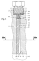
- FIGs 1, 4 and 6 is formed with 10 from the combustion chamber of an internal combustion engine Designated pressure chamber in which the pressure of the hot combustion gas is to be detected.
- the pressure chamber 10 is of a combustion chamber wall 11 of the internal combustion engine enclosed.
- a bore 13 with a pressure chamber side, inner opening 14 and a sensor-side, outer opening 15 is introduced.
- a receptacle 17 is formed, in which a pressure sensor 20 with a sensor surface 21 is screwed.
- the sensor surface 21 faces into a pressure chamber 18.
- the bore 13 is in the embodiment of Figure 1 and 4 at the inner Opening 14 with a conical portion 16 executed.
- an insert 30 is located in the bore 13 with a pressure-chamber-side end face 34 and a sensor-side end face 35.
- Der Insert 30 has axially extending, for example, a pressure-transmitting channels 31, which connects the pressure chamber 10 with the pressure chamber 18.
- the pressure chamber 18 is in front of the sensor surface 21 and is between the sensor-side end face 35th the insert 30 and the sensor surface 21 formed within the bore 13.
- the But pressure chamber 18 may also at least partially into the receptacle 17 for the Be integrated pressure sensor 20.
- the channel 31 tapers or narrows from the pressure chamber-side end face 34 towards the sensor-side end face 35 wedge-shaped. By the narrowing of the channel 31 to the pressure chamber 18 is the pressure transmission from Pressure chamber 10 to the pressure sensor 20 de-throttled.
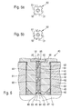
- FIG. 2 shows a second embodiment of the insert 31 for the exemplary embodiment shown in FIG.
- the channel 31 extends to the pressure transmission of the pressure-chamber-side end face 34 to the sensor-side end face 35 wedge-shaped.
- the insert 30 is adapted to the bore 13 in diameter and substantially inserted into the bore 13 without play.
- a conical support surface 33 which on the conical portion 16 of the bore 13 rests, so that the insert 30 in the direction of the pressure chamber 10 in the bore 13th is fixed.
- a compression spring 25 is arranged, so that the insert 30th is axially biased within the bore 13.
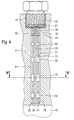
- an insert 50 is located in the bore 13 with a pressure-chamber-side end face 54 and a sensor-side end face 55.
- Der Insert 50 has axially extending, pressure-transmitting channels 51 and, for example radially extending, vibration-damping annular spaces 52.
- the insert 50 is - like the insert 30 in Figures 1 and 2 - adapted to the bore 13 in diameter and in the Substantially backlash inserted into the bore 13.
- the insert 50 also has a conical support surface 53 which on conical portion 16 of the bore 13 rests.
- the channels 51 formed in the insert 50 have, for example, those shown in FIGS. 5a and 5b illustrated cross-sectional profiles and connect the burner chamber 10 with the Pressure chamber 18.
- FIGS. 5a and 5b illustrated cross-sectional profiles and connect the burner chamber 10 with the Pressure chamber 18.
- the embodiment according to FIG. 6 shows a sensor component 40 with a Einschraubgephaseuse 41.
- the screw-41 has a thread 42 which in a Threaded 43 of the combustion chamber wall 11 of the engine screwed becomes.
- Einschraubgephase 41 is an axially extending bore 44 with a pressure-chamber-side, inner opening 45 and a sensor-side outer opening 46th educated.
- the axial bore 44 is extended from one Surrounded by annulus 47.
- the bore 44 opens into a Recording 48, in which the pressure sensor 20 is fixed, wherein the pressure sensor 20 also here a space is connected upstream as a pressure chamber 18.
- an insert 60 with a pressure chamber side End face 64 and a sensor-side end face 65 which in connection with the Embodiments in Figures 1 and 4 have described embodiments can.
- the insert 60 analogous to Embodiment in Figure 4 with pressure-transmitting channels 61 pressure vibration damping annular spaces 62 on.
- the insert 60 is shown in FIG. 6 the pressure-chamber-side end face 64 along the inner circumference of the annular space 47 with a weld 49 attached. This eliminates the axial described in Figures 1 and 4 Fixation by means of a compression spring.
- the Insert 60 further example, according to the number of channels 61st Connecting bores 63 which a connection between the pressure chamber 10 and make the channels 61.
- the channels 31, 51, 61 are used for pressure transmission of the ruling in the pressure chamber 10 Pressure on the sensor surface 21 of the pressure sensor 20, wherein the sensor surface 21st for example, may be a sensor membrane.
- Hemholtz resonator Hemholtz resonator
- phase delay and the attenuation of the sensor signal are approximately systematic and can be corrected by appropriate maps in a control unit.
- Prerequisite for a long-term use is also that the channels 31, 51, 61 do not clog by coking.
Abstract
Description
Die Erfindung betrifft eine Anordnung zur Druckerfassung in einem Druckraum, insbesondere in einem Brennraum einer Brennkraftmaschine, nach dem Oberbegriff des Anspruchs 1.The invention relates to an arrangement for pressure detection in a pressure chamber, in particular in a combustion chamber of an internal combustion engine, according to the preamble of Claim 1.
Anordnungen zur Druckerfassung von heißen Druckmedien, welche zum Beispiel zur Messung des Brennraumdrucks an Brennkraftmaschinen bestimmt sind, sind so aufgebaut, dass der Drucksensor vor den im Brennraum auftretenden hohen Temperaturen zu schützen ist. Dabei ist aus EP 702 784 B1 bekannt, den Drucksensor von der Wärmequelle distanziert am Gehäuse der Brennkraftmaschine anzuordnen und zwischen Drucksensor und Brennraum eine Bohrung vorzusehen, die brennraumseitig mit einer Membran verschlossen ist und in der ein Stempel geführt ist, der den auf die Membran wirkenden Druck auf den Drucksensor überträgt.Arrangements for pressure detection of hot print media, which, for example, to Measurement of the combustion chamber pressure are determined on internal combustion engines are so constructed so that the pressure sensor before occurring in the combustion chamber high To protect temperatures. It is known from EP 702 784 B1, the pressure sensor distance from the heat source to the housing of the internal combustion engine to arrange and between the pressure sensor and the combustion chamber to provide a bore, the combustion chamber side with a membrane is closed and in which a stamp is guided, the on the Membrane acting pressure on the pressure sensor transmits.
Darüber hinaus ist aus EP 145 146 A1 bekannt, an Stelle des Stempels eine gut wärmeleitende, inkompressible Flüssigkeit zur Druckübertragung zu verwenden.In addition, EP 145 146 A1 is known, in place of the punch a good to use heat-conducting, incompressible liquid for pressure transmission.
Aufgabe der vorliegenden Erfindung ist es, eine Anordnung zur Druckerfassung von heißen Druckmedien zu schaffen, die einfach realisierbar ist. Object of the present invention is an arrangement for pressure detection of to create hot print media that is easy to implement.
Die erfindungsgemäße Anordnung mit den kennzeichnenden Maßnahmen des Anspruchs 1 hat den Vorteil, dass eine einfache Druckerfassung von heißen Druckmedien möglich ist, die ohne ein bewegliches mechanisches Bauteil zur Druckübertragung auskommt. Der am Einsatz ausgebildete druckübertragende Kanal ist fertigungstechnisch einfach herstellbar. Die Verwendung von Serien-Hochdrucksensoren mit beispielsweise einer 200 bar Membran ist möglich.The arrangement according to the invention with the characterizing measures of the claim 1 has the advantage that a simple pressure detection of hot media possible is that manages without a moving mechanical component for pressure transmission. Of the trained on use pressure-transmitting channel is easy to manufacture produced. The use of series high-pressure sensors with, for example, a 200 bar membrane is possible.
Vorteilhafte Weiterbildungen der Erfindung sind durch die Maßnahmen der Unteransprüche möglich. Mittels eines sich verengenden oder sich erweiternden Verlaufes des druckübertragenden Kanals lässt sich auf einfache Weise eine gedrosselte bzw. entdrosselte Druckübertragung vom Druckraum zum Drucksensor realisieren. Eine gedrosselte Druckübertragung liegt vor, wenn im Eingangsbereich des druckübertagenden Kanals mit relativ geringem Querschnitt die Strömung Schallgeschwindigkeit erreicht. Der Druckanstieg im relativ großen Volumen vor dem Drucksensor wird dann verzögert, wodurch störende Resonanzfrequenzen des Übertragungskanals gedämpft werden. Jedoch gehen anderseits dadurch auch Signalinformationen verloren. Bei der entdrosselte Drückübertagung wird dieser Nachteil durch die stetige Kanalverengung verhindert, da im Eingangsbereich des druckübertagenden Kanals ein großer Querschnitt vorliegt und das Volumen vor dem Drucksensor klein ist. Hierbei genügt eine geringere Strömungsgeschwindigkeit, um das Drucksignal zu übertragen. Jedoch kann dabei nicht ausgeschlossen werden, dass Resonanzen das Nutzsignal überlagern. Besonders zweckmäßig ist es, einen an die Bohrung angepassten zylindrischen Einsatz mit mindestens einem druckübertagenden Kanal zu verwenden. Zweckmäßig ist ferner die Integration mindestens eines druckschwingungsdämpfenden Raumes. Der druckschwingungsdämpfende Raum bewirkt, dass die Entstehung von Druckschwingungen und Resonanzen bei der Druckübertragung auf den Drucksensor weitestgehend vermieden wird. Das Entstehen von Pfeifschwingungen im Sensorkopf wird somit ebenfalls unterbunden. Dazu ist es vorteilhaft, wenn der mindestens eine axial verlaufende, druckübertragende Kanal radial eingearbeitete Ringräume zur Dämpfung von Druckschwingungen aufweist. Die in die Mantelfläche des Einsatz eingebrachten druckschwingungsdämpfenden Ringräume sind fertigungstechnisch einfach herstellbar. Ein komplett auswechselbares Bauteil mit Einsatz und Drucksensor lässt sich dadurch schaffen, indem Einsatz und Drucksensor in einem beispielsweise einschraubbaren Bauteil integriert sind.Advantageous developments of the invention are achieved by the measures of Subclaims possible. By means of a narrowing or widening History of the pressure-transmitting channel can be easily throttled or Entschrosselte pressure transfer from the pressure chamber to the pressure sensor realize. A Throttled pressure transmission is present when in the input area of the pressure-transmitting channel with a relatively small cross-section of the flow Sound velocity reached. The pressure increase in the relatively large volume before Pressure sensor is then delayed, causing disturbing resonance frequencies of the Transmission channels are attenuated. However, on the other hand, this also goes by the way Lost signal information. In the case of the throttled pressure transfer this disadvantage becomes prevented by the constant channel narrowing, since in the entrance area of pressure-transmitting channel is a large cross section and the volume before the Pressure sensor is small. Here, a lower flow rate is sufficient to the To transmit pressure signal. However, it can not be ruled out that Resonances superimpose the useful signal. It is particularly useful, one to the Bore adapted cylindrical insert with at least one druckübertagenden Channel to use. It is also expedient to integrate at least one pressure-vibration-damping space. The pressure-vibration-damping space causes the formation of pressure oscillations and resonances in the Pressure transfer to the pressure sensor is largely avoided. The emergence Whistling in the sensor head is thus likewise prevented. That's it advantageous if the at least one axially extending, pressure-transmitting channel radially has incorporated annular spaces for damping pressure oscillations. The in the The lateral surface of the insert introduced pressure-vibration-damping annular spaces are production technology easy to produce. A completely replaceable component with insert and pressure sensor can be created by insert and pressure sensor in one For example, screw-in component are integrated.
Ausführungsbeispiele der Erfindung sind in der Zeichnung dargestellt und in der nachfolgenden Beschreibung näher erläutert.Embodiments of the invention are illustrated in the drawing and in the following Description explained in more detail.
Es zeigen
- Figur 1
- eine Schnittdarstellung durch ein erstes Ausführungsbeispiel der erfindungsgemäßen Anordnung,
- Figur 2
- eine Schnittdarstellung durch einen Einsatz gemäß einer zweiten Ausführungsform für das Ausführungsbeispiel in Figur 1,
- Figur 3a
- eine Schnittdarstellung durch den Einsatz nach der Linie IIIa - IIIa in Figur 1,
- Figur 3b
- eine Draufsicht auf den Einsatz in Richtung III b in Figur 2,
- Figur 4
- eine Schnittdarstellung durch ein zweites Ausführungsbeispiel der erfindungsgemäßen Anordnung,
- Figur 5a
- eine Schnittdarstellung durch einen Einsatz nach der Linie V - V in Figur 4 gemäß einer ersten Ausführungsform für das Ausführungsbeispiel in Figur 4,
- Figur 5b
- eine Schnittdarstellung eines Einsatzes nach der Linie V - V in Figur 4 gemäß einer zweiten Ausführungsform für das Ausführungsbeispiel in Figur 4 und
- Figur 6
- ein drittes Ausführungsbeispiel der erfindungsgemäßen Anordnung zur Druckerfassung.
- FIG. 1
- a sectional view through a first embodiment of the inventive arrangement,
- FIG. 2
- a sectional view through an insert according to a second embodiment for the embodiment in Figure 1,
- FIG. 3a
- a sectional view through the insert according to the line IIIa - IIIa in Figure 1,
- FIG. 3b
- a top view of the insert in direction III b in Figure 2,
- FIG. 4
- a sectional view through a second embodiment of the inventive arrangement,
- FIG. 5a
- 3 is a sectional view through an insert according to the line V-V in FIG. 4 according to a first embodiment for the exemplary embodiment in FIG. 4,
- FIG. 5b
- a sectional view of an insert along the line V - V in Figure 4 according to a second embodiment of the embodiment in Figure 4 and
- FIG. 6
- A third embodiment of the inventive arrangement for pressure detection.
In Figur 1, 4 und 6 ist mit 10 ein vom Brennraum einer Brennkraftmaschine gebildeter
Druckraum bezeichnet, in dem der Druck des heißen Verbrennungsgases zu erfassen ist.
Der Druckraum 10 ist dabei von einer Brennraumwand 11 der Brennkraftmaschine
umschlossen. In die Brennraumwand 11 ist eine Bohrung 13 mit einer druckraumseitigen,
inneren Öffnung 14 und einer sensorseitigen, äußeren Öffnung 15 eingebracht. An der
äußeren Öffnung 15 ist eine Aufnahme 17 ausgebildet, in die ein Drucksensor 20 mit
einer Sensorfläche 21 eingeschraubt ist. Die Sensorfläche 21 weist in eine Druckkammer
18. Die Bohrung 13 ist beim Ausführungsbeispiel gemäß Figur 1 und 4 an der inneren
Öffnung 14 mit einem konischen Abschnitt 16 ausgeführt.In Figures 1, 4 and 6 is formed with 10 from the combustion chamber of an internal combustion engine
Designated pressure chamber in which the pressure of the hot combustion gas is to be detected.
The
Beim Ausführungsbeispiel gemäß Figur 1 befindet sich in der Bohrung 13 ein Einsatz 30
mit einer druckraumseitigen Stirnfläche 34 und einer sensorseitigen Stirnfläche 35. Der
Einsatz 30 weist axial verlaufend beispielsweise einen druckübertragende Kanale 31 auf,
der den Druckraum 10 mit der Druckkammer 18 verbindet. Die Druckkammer 18 ist
dabei der Sensorfläche 21 vorgelagert und ist zwischen der sensorseitigen Stirnfläche 35
des Einsatzes 30 und der Sensorfläche 21 innerhalb der Bohrung 13 ausgebildet. Die
Druckkammer 18 kann aber auch zumindest teilweise in die Aufnahme 17 für den
Drucksensor 20 integriert sein. Der Kanal 31 verjüngt bzw. verengt sich von der
druckraumseitigen Stirnfläche 34 hin zur sensorseitigen Stirnfläche 35 keilförmig. Durch
die Verengung des Kanals 31 zur Druckkammer 18 hin wird die Druckübertragung vom
Druckraum 10 zum Drucksensor 20 entdrosselt.In the embodiment according to FIG. 1, an
In Figur 2 ist eine zweite Ausführungsform des Einsatzes 31 für das Ausführungsbeispiel
in Figur 1 gezeigt. Hierbei erweitert sich der Kanal 31 zur Druckübertragung von der
druckraumseitigen Stirnfläche 34 zur sensorseitigen Stirnfläche 35 hin keilförmig. Durch
diesen sich erweiternden Verlauf des Kanals 31 entsteht eine gedrosselte
Druckübertragung vom Druckraum 10 zur Druckkammer 18 und damit zum Drucksensor
20 hin.FIG. 2 shows a second embodiment of the
Der Einsatz 30 ist an die Bohrung 13 im Durchmesser angepasst und im Wesentlichen
spielfrei in die Bohrung 13 eingesetzt. An der druckraumseitigen Stirnfläche 34 weist der
Einsatz 30 eine konische Stützfläche 33 auf, die am konischen Abschnitt 16 der Bohrung
13 aufliegt, so dass der Einsatz 30 in Richtung des Druckraums 10 in der Bohrung 13
festgelegt ist. Um eine axiale Verschiebung des Einsatzes 30 innerhalb der Bohrung 13 zu
verhindern, ist zwischen einer Auflagefläche am Drucksensor 20 und der sensorseitigen
Stirnfläche 35 des Einsatzes 30 eine Druckfeder 25 angeordnet, so dass der Einsatz 30
innerhalb der Bohrung 13 axial vorgespannt ist. Der im Einsatz 30 der Figuren 1 und 2
ausgebildete Kanal 31 weist beispielsweise die in Figur 3a und 3b dargestellten
rechteckförmigen Querschnittsprofile auf. The
Beim Ausführungsbeispiel gemäß Figur 4 befindet sich in der Bohrung 13 ein Einsatz 50
mit einer druckraumseitigen Stirnfläche 54 und einer sensorseitigen Stirnfläche 55. Der
Einsatz 50 weist axial verlaufende, druckübertragende Kanäle 51 und beispielsweise
radial verlaufende, schwingungsdämpfende Ringräume 52 auf. Der Einsatz 50 ist - wie
der Einsatz 30 in Figur 1 und 2 - an die Bohrung 13 im Durchmesser angepasst und im
Wesentlichen spielfrei in die Bohrung 13 eingesetzt. An der druckraumseitigen
Stirnfläche 54 weist der Einsatz 50 ebenfalls eine konische Stützfläche 53 auf, die am
konischen Abschnitt 16 der Bohrung 13 aufliegt. Um eine axiale Verschiebung des
Einsatzes 50 innerhalb der Bohrung 13 zu verhindern, ist zwischen einer Auflagefläche
am Drucksensor 20 und der sensorseitigen Stirnfläche 55 des Einsatzes 50 die bereist in
Figur 1 dargestellte Druckfeder 25 angeordnet, so dass der Einsatz 50 innerhalb der
Bohrung 13 axial vorgespannt ist.In the embodiment according to FIG. 4, an
Die im Einsatz 50 ausgebildeten Kanäle 51 weisen beispielsweise die in Figur 5a und 5b
dargestellten Querschnittsprofile auf und verbinden die Brennerkammer 10 mit der
Druckkammer 18. Dabei sind die an der Mantelfläche des Einsatzes 50 verlaufenden
axialen Kanäle 51 gemäß Figur 5a mit einem halbkreisförmigen Querschnitt und gemäß
Figur 5b mit einem rechteckförmigen Querschnitt ausgeführt.The
Das Ausführungsbeispiel gemäß Figur 6 zeigt ein Sensorbauteil 40 mit einem
Einschraubgehäuse 41. Das Einschraubgehäuse 41 weist ein Gewinde 42 auf, das in eine
Gewindeaufnahme 43 der Brennraumwand 11 der Brennkraftmaschine eingeschraubt
wird. Im Einschraubgehäuse 41 ist eine axial verlaufende Bohrung 44 mit einer
druckraumseitigen, inneren Öffnung 45 und einer sensorseitigen, äußeren Öffnung 46
ausgebildet. An der inneren Öffnung 45 ist die axiale Bohrung 44 von einem erweiterten
Ringraum 47 umgeben. An der äußeren Öffnung 46 mündet die Bohrung 44 in eine
Aufnahme 48, in der der Drucksensor 20 fixiert ist, wobei dem Drucksensor 20 auch hier
ein Raum als Druckkammer 18 vorgeschaltet ist.The embodiment according to FIG. 6 shows a
Innerhalb der Bohrung 44 befmdet sich ein Einsatz 60 mit einer druckraumseitigen
Stirnfläche 64 und einer sensorseitigen Stirnfläche 65, der die im Zusammenhang mit den
Ausführungsbeispielen in Figur 1 und 4 beschriebenen Ausführungsformen aufweisen
kann. Beim Ausführungsbeispiel gemäß Figur 6 weist der Einsatz 60 analog dem
Ausführungsbeispiel in Figur 4 drückübertragende Kanäle 61 mit
druckschwingungsdämpfenden Ringräumen 62 auf. Der Einsatz 60 ist gemäß Figur 6 an
der druckraumseitigen Stirnfläche 64 entlang des inneren Umfangs des Ringraums 47 mit
einer Schweißnaht 49 befestigt. Dadurch entfällt die in Figur 1 und 4 beschriebene axiale
Fixierung mittels einer Druckfeder. An der druckraumseitigen Stirnfläche 64 weist der
Einsatz 60 weiterhin beispielsweise entsprechend der Anzahl der Kanäle 61
Verbindungsbohrungen 63 auf, die eine Verbindung zwischen dem Druckraum 10 und
den Kanälen 61 herstellen.Within the
Die Kanäle 31, 51, 61 dienen zur Druckübertragung des im Druckraum 10 herrschende
Drucks auf die Sensorfläche 21 des Drucksensors 20, wobei die Sensorfläche 21
beispielsweise eine Sensormembran sein kann. Die im Zusammenhang mit Figur 4 und 7
beschriebenen druckschwingungsdämpfenden Ringräume 32, 62 bewirken, dass
Druckschwingungen und Resonanzen bei der Druckübertragung auf den Drucksensor 20
weitestgehend unterbunden werden. Es ist aber genauso denkbar, einen von den Kanälen
31 abzweigenden Resonatorraum (Hemholtz-Resonator) zur Dämpfung einzusetzen.The
Der Phasenverzug und die Dämpfung des Sensorsignals sind annähernd systematisch und
können durch entsprechende Kennfelder in einem Steuergerät korrigiert werden.
Voraussetzung für einen Langzeiteinsatz ist es außerdem, dass sich die Kanäle 31, 51, 61
nicht durch Verkokung zusetzen. The phase delay and the attenuation of the sensor signal are approximately systematic and
can be corrected by appropriate maps in a control unit.
Prerequisite for a long-term use is also that the
- 1010
- Druckraumpressure chamber
- 1111
- BrennraumwandCombustion chamber wall
- 1313
- Bohrungdrilling
- 1414
- innere Öffnunginner opening
- 1515
- äußere Öffnungouter opening
- 1616
- konischer Abschnittconical section
- 1717
- Aufnahmeadmission
- 1818
- Druckkammerpressure chamber
- 2020
- Drucksensorpressure sensor
- 2121
- Sensorflächesensor surface
- 2525
- Druckfedercompression spring
- 3030
- Einsatzcommitment
- 3131
- druckübertragender Kanalpressure transmitting channel
- 3333
- konische Stützflächeconical support surface
- 3434
- druckraumseitige Stirnflächepressure chamber-side end face
- 3535
- sensorseitige Stirnflächesensor-side end face
- 4040
- Sensorbauteilsensor component
- 4141
- Einschraubgehäusescrew-in
- 4242
- Gewindethread
- 4343
- Gewindeaufnahmethreaded receptacle
- 4444
- axiale Bohrungaxial bore
- 4545
- druckraumseitige Öffnungpressure-chamber-side opening
- 4646
- sensorseitige Öffnungsensor-side opening
- 4747
- Ringraumannulus
- 4848
- Aufnahmeadmission
- 4949
- SchweißnahtWeld
- 5050
- Einsatzcommitment
- 5151
- druckübertragender Kanalpressure transmitting channel
- 5252
- druckschwingungsdämpfender Raumpressure-vibration-damping space
- 5353
- konische Stützflächeconical support surface
- 5454
- druckraumseitige Stirnflächepressure chamber-side end face
- 5555
- sensorseitige Stirnfläche sensor-side end face
- 6060
- Einsatzcommitment
- 6161
- druckübertragender Kanalpressure transmitting channel
- 6262
- druckschwingungsdämpfender Raumpressure-vibration-damping space
- 6363
- Verbindungsbohrungenconnecting bores
- 6464
- druckraumseitige Stirnflächepressure chamber-side end face
- 6565
- sensorseitige Stirnflächesensor-side end face
Claims (10)
Applications Claiming Priority (2)
| Application Number | Priority Date | Filing Date | Title |
|---|---|---|---|
| DE200410002089 DE102004002089A1 (en) | 2004-01-15 | 2004-01-15 | Arrangement for pressure detection in a pressure chamber, in particular in a combustion chamber of an internal combustion engine |
| DE102004002089 | 2004-01-15 |
Publications (2)
| Publication Number | Publication Date |
|---|---|
| EP1555518A2 true EP1555518A2 (en) | 2005-07-20 |
| EP1555518A3 EP1555518A3 (en) | 2006-04-19 |
Family
ID=34609563
Family Applications (1)
| Application Number | Title | Priority Date | Filing Date |
|---|---|---|---|
| EP04105834A Withdrawn EP1555518A3 (en) | 2004-01-15 | 2004-11-17 | Arrangement for sensing pressure in a pressurized space, in particular in a combustion chamber of a combustion engine |
Country Status (3)
| Country | Link |
|---|---|
| EP (1) | EP1555518A3 (en) |
| JP (1) | JP2005201906A (en) |
| DE (1) | DE102004002089A1 (en) |
Cited By (4)
| Publication number | Priority date | Publication date | Assignee | Title |
|---|---|---|---|---|
| EP2442084A1 (en) * | 2010-10-14 | 2012-04-18 | Rolls-Royce plc | Presure indicator with means for minimizing resonance frequencies |
| US20130263671A1 (en) * | 2012-04-10 | 2013-10-10 | General Electric Company | Fluid pressure spike attenuation feature for pressure sensing devices |
| US8650962B2 (en) | 2010-10-14 | 2014-02-18 | Rolls-Royce Plc | Pressure indicator |
| US8667848B2 (en) | 2010-10-14 | 2014-03-11 | Rolls-Royce Plc | Pressure indicator |
Families Citing this family (2)
| Publication number | Priority date | Publication date | Assignee | Title |
|---|---|---|---|---|
| JP2011247883A (en) * | 2010-04-28 | 2011-12-08 | Nippon Soken Inc | Cylindrical internal pressure detecting device |
| DE102014010116B4 (en) | 2013-04-29 | 2018-11-15 | Elmos Semiconductor Aktiengesellschaft | MEMS sensor for difficult environments and media |
Citations (2)
| Publication number | Priority date | Publication date | Assignee | Title |
|---|---|---|---|---|
| US3540285A (en) * | 1967-05-03 | 1970-11-17 | Inst Cercetari Si Proiectari P | Apparatus for damping pulsating pressures in pressure gauges |
| US5483835A (en) * | 1993-10-13 | 1996-01-16 | Saturn Electronics & Engineering, Inc. | Oil pressure sender unit with reinforced diaphragm |
-
2004
- 2004-01-15 DE DE200410002089 patent/DE102004002089A1/en not_active Withdrawn
- 2004-11-17 EP EP04105834A patent/EP1555518A3/en not_active Withdrawn
-
2005
- 2005-01-17 JP JP2005009565A patent/JP2005201906A/en active Pending
Patent Citations (2)
| Publication number | Priority date | Publication date | Assignee | Title |
|---|---|---|---|---|
| US3540285A (en) * | 1967-05-03 | 1970-11-17 | Inst Cercetari Si Proiectari P | Apparatus for damping pulsating pressures in pressure gauges |
| US5483835A (en) * | 1993-10-13 | 1996-01-16 | Saturn Electronics & Engineering, Inc. | Oil pressure sender unit with reinforced diaphragm |
Cited By (6)
| Publication number | Priority date | Publication date | Assignee | Title |
|---|---|---|---|---|
| EP2442084A1 (en) * | 2010-10-14 | 2012-04-18 | Rolls-Royce plc | Presure indicator with means for minimizing resonance frequencies |
| US8573061B2 (en) | 2010-10-14 | 2013-11-05 | Rolls-Royce Plc | Pressure indicator |
| US8650962B2 (en) | 2010-10-14 | 2014-02-18 | Rolls-Royce Plc | Pressure indicator |
| US8667848B2 (en) | 2010-10-14 | 2014-03-11 | Rolls-Royce Plc | Pressure indicator |
| US20130263671A1 (en) * | 2012-04-10 | 2013-10-10 | General Electric Company | Fluid pressure spike attenuation feature for pressure sensing devices |
| WO2013154800A1 (en) * | 2012-04-10 | 2013-10-17 | General Electric Company | Fluid pressure spike attenuation feature for pressure sensing devices |
Also Published As
| Publication number | Publication date |
|---|---|
| DE102004002089A1 (en) | 2005-08-04 |
| JP2005201906A (en) | 2005-07-28 |
| EP1555518A3 (en) | 2006-04-19 |
Similar Documents
| Publication | Publication Date | Title |
|---|---|---|
| DE3122375C2 (en) | Sensor arrangement | |
| EP1125043B1 (en) | Flat tubular pressure damper for damping fluid pressure oscillations in fluid lines | |
| DE4125316C1 (en) | ||
| EP2131171B1 (en) | Measurement device | |
| EP3464870A1 (en) | High-pressure accumulator and method for producing a high-pressure accumulator | |
| EP3175207A1 (en) | Diaphragm seal and pressure sensor having a diaphragm seal | |
| EP1555518A2 (en) | Arrangement for sensing pressure in a pressurized space, in particular in a combustion chamber of a combustion engine | |
| DE19942370A1 (en) | Injection nozzle for internal combustion engines with an annular groove in the nozzle needle | |
| WO2009132879A2 (en) | Fuel injection device | |
| DE102014211952A1 (en) | Hydro bearing and motor vehicle with such a hydraulic bearing | |
| DE102005022698B4 (en) | Rückströmdrosselventil for a fuel injection device of an internal combustion engine | |
| DE102007000752A1 (en) | Air intake control device | |
| EP1076771B1 (en) | Fuel injection valve for internal combustion engines | |
| DE102006039540B4 (en) | Pressure pulsation damper for a hydraulic power steering system of a motor vehicle | |
| WO2002061265A1 (en) | Valve for controlling fluids | |
| EP3111187B1 (en) | Glow-plug adapter | |
| DE102017202933A1 (en) | Fuel injection valve for injecting a gaseous and / or liquid fuel | |
| EP2823176B1 (en) | Valve for metering a fluid | |
| DE102016225767A1 (en) | damping valve | |
| DE3047110C2 (en) | ||
| EP1157208B1 (en) | Injection nozzle with blind bore for internal combustion engine with rounded passage between the blind bore and the injector needle seat | |
| DE102015121629A1 (en) | Pressure transducer with flame arrester | |
| DE19956929B4 (en) | Oil pressure regulating valve | |
| EP1076770B1 (en) | Fuel injection valve for internal combustion engines | |
| EP2840374B1 (en) | Orifice for a sensor arrangement |
Legal Events
| Date | Code | Title | Description |
|---|---|---|---|
| PUAI | Public reference made under article 153(3) epc to a published international application that has entered the european phase |
Free format text: ORIGINAL CODE: 0009012 |
|
| AK | Designated contracting states |
Kind code of ref document: A2 Designated state(s): AT BE BG CH CY CZ DE DK EE ES FI FR GB GR HU IE IS IT LI LU MC NL PL PT RO SE SI SK TR |
|
| AX | Request for extension of the european patent |
Extension state: AL HR LT LV MK YU |
|
| PUAL | Search report despatched |
Free format text: ORIGINAL CODE: 0009013 |
|
| AK | Designated contracting states |
Kind code of ref document: A3 Designated state(s): AT BE BG CH CY CZ DE DK EE ES FI FR GB GR HU IE IS IT LI LU MC NL PL PT RO SE SI SK TR |
|
| AX | Request for extension of the european patent |
Extension state: AL HR LT LV MK YU |
|
| AKX | Designation fees paid | ||
| STAA | Information on the status of an ep patent application or granted ep patent |
Free format text: STATUS: THE APPLICATION IS DEEMED TO BE WITHDRAWN |
|
| 18D | Application deemed to be withdrawn |
Effective date: 20061020 |
|
| REG | Reference to a national code |
Ref country code: DE Ref legal event code: 8566 |