EP1555501A1 - Regenerative rotary refrigerator/heat exchanger with intermediary fluid and phase change - Google Patents
Regenerative rotary refrigerator/heat exchanger with intermediary fluid and phase change Download PDFInfo
- Publication number
- EP1555501A1 EP1555501A1 EP02751194A EP02751194A EP1555501A1 EP 1555501 A1 EP1555501 A1 EP 1555501A1 EP 02751194 A EP02751194 A EP 02751194A EP 02751194 A EP02751194 A EP 02751194A EP 1555501 A1 EP1555501 A1 EP 1555501A1
- Authority
- EP
- European Patent Office
- Prior art keywords
- fluid
- heat exchanger
- fluids
- blades
- phase change
- Prior art date
- Legal status (The legal status is an assumption and is not a legal conclusion. Google has not performed a legal analysis and makes no representation as to the accuracy of the status listed.)
- Withdrawn
Links
Images


Classifications
-
- F—MECHANICAL ENGINEERING; LIGHTING; HEATING; WEAPONS; BLASTING
- F28—HEAT EXCHANGE IN GENERAL
- F28D—HEAT-EXCHANGE APPARATUS, NOT PROVIDED FOR IN ANOTHER SUBCLASS, IN WHICH THE HEAT-EXCHANGE MEDIA DO NOT COME INTO DIRECT CONTACT
- F28D11/00—Heat-exchange apparatus employing moving conduits
- F28D11/02—Heat-exchange apparatus employing moving conduits the movement being rotary, e.g. performed by a drum or roller
-
- F—MECHANICAL ENGINEERING; LIGHTING; HEATING; WEAPONS; BLASTING
- F28—HEAT EXCHANGE IN GENERAL
- F28D—HEAT-EXCHANGE APPARATUS, NOT PROVIDED FOR IN ANOTHER SUBCLASS, IN WHICH THE HEAT-EXCHANGE MEDIA DO NOT COME INTO DIRECT CONTACT
- F28D15/00—Heat-exchange apparatus with the intermediate heat-transfer medium in closed tubes passing into or through the conduit walls ; Heat-exchange apparatus employing intermediate heat-transfer medium or bodies
- F28D15/02—Heat-exchange apparatus with the intermediate heat-transfer medium in closed tubes passing into or through the conduit walls ; Heat-exchange apparatus employing intermediate heat-transfer medium or bodies in which the medium condenses and evaporates, e.g. heat pipes
- F28D15/0208—Heat-exchange apparatus with the intermediate heat-transfer medium in closed tubes passing into or through the conduit walls ; Heat-exchange apparatus employing intermediate heat-transfer medium or bodies in which the medium condenses and evaporates, e.g. heat pipes using moving tubes
-
- F—MECHANICAL ENGINEERING; LIGHTING; HEATING; WEAPONS; BLASTING
- F28—HEAT EXCHANGE IN GENERAL
- F28D—HEAT-EXCHANGE APPARATUS, NOT PROVIDED FOR IN ANOTHER SUBCLASS, IN WHICH THE HEAT-EXCHANGE MEDIA DO NOT COME INTO DIRECT CONTACT
- F28D7/00—Heat-exchange apparatus having stationary tubular conduit assemblies for both heat-exchange media, the media being in contact with different sides of a conduit wall
- F28D7/10—Heat-exchange apparatus having stationary tubular conduit assemblies for both heat-exchange media, the media being in contact with different sides of a conduit wall the conduits being arranged one within the other, e.g. concentrically
- F28D7/106—Heat-exchange apparatus having stationary tubular conduit assemblies for both heat-exchange media, the media being in contact with different sides of a conduit wall the conduits being arranged one within the other, e.g. concentrically consisting of two coaxial conduits or modules of two coaxial conduits
Definitions
- this device is also possible in the cooling of blades in the hot gas path areas, showing a clear application as cooler of materials located in hot gas areas, increasing this way the useful life of this components, as well as their substitution by others of lower heat resistant characteristics reducing costs.
- both fluids are conducted to the hollow rotating blades that are the heat exchange pieces, both fluids get across the blades without mixing, because there is a sealing system between both fluids, and at the exit of the blades the fluids are conducted using the concentrical scheme to the areas where they are required.
- Concentrical conduction are only required at the inlet and outlet of the heat exchanger, being any other disposition possible before or after the exchanger.
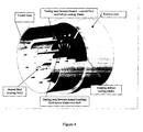
- Refrigeration takes place in the hollow blades as follows.
- a liquid that is able to have a phase change to gas between the temperatures of the cooling and cooled fluids (i.e. at cooling fluid temperature the inner fluid of the blades is liquid and at the cooled fluid temperature is gas).
- the fluid inside the blades gasified in the external area of the blade is rotating as well as the blade, and as long as the fluid located in the inner area of the blade is still liquid it will push down the gas to the inner part of the blade (this happens due to the rotation force on the liquid part of the fluid that is more dense that the gas phase and it is pushed to the external area of the blade), in this area the gas will be liquefied again because of the temperature of the external fluid circulating into the inner pipe that will be heated by the heat exchange phase of the inner blade fluid.
- This working cycle is continuos , providing the centre of rotation of the blades is coincident with the centre of both concentrical conductions.
- FIG. 2 shows an scheme of the described process.
- External and internal walls of the blades will be designed in a way that increases as much as possible the HTC, using ribs, turbulators, or whaterever improved design.
- the rotation of the blades can be achieved using an external motor or, in order to get a better efficiency, using the energy available in the fluids to cool - heat designing the blades in an adequate mode. It can be seen a scheme of design of the blades powered by fluids in figure 3.
- the transition of the fluids from the static zone (concentrical pipes) to the rotating one (blades) will be designed using adequate sealing systems depending on the fluids (i.e. labyrinth seals, gas seals, mechanical seals..).
- the same device is also useful to cool down the material of the blades located in the hot fluid path, because as long as in the inner hollow are is all the time circulating a mixture of the inner gas liquid fluid, the temperature of this mixing is always lower than the one of the fluid located in the external area of the blade, so the blade material temperature is sensibly reduced.
- the design in its heat exchanger version is applicable to whatever industrial field requiring an efficient heat exchange. Clear immediate application examples can be found in gas or steam turbines for the cooling of different stages, secondary airflow preconditioning or preheating of heavy fuels. In petrochemical or industrial plants to heat or cool several process fluids. In terrestrial vehicles, ships or planes to cool down engines and heating the air-conditioned for passengers. In air conditioning systems to reduce their size and achieve better efficiencies, ...
- the design in its material cooling version it can be applied immediately in all type of turbo machinery that deals with hot fluids to refrigerate turbo machinery components located in the hot fluid path.
- Figure 4 shows cooling and cooling fluids circulating in the same direction to simplify the figure, not existing in the design any obstacle to make both fluids to circulate in different directions as we have told before.
- Figure 6 shows a front view showing inlet of both fluids to the device.
- Figure 7 shows the blades transparent to allow the viewing of the concentrical disposition of the concentrical conducts.
Landscapes
- Engineering & Computer Science (AREA)
- Physics & Mathematics (AREA)
- Thermal Sciences (AREA)
- Mechanical Engineering (AREA)
- General Engineering & Computer Science (AREA)
- Life Sciences & Earth Sciences (AREA)
- Sustainable Development (AREA)
- Heat-Exchange Devices With Radiators And Conduit Assemblies (AREA)
Abstract
Description
- Mass flows of the cooling and cooled fluids.
- Adaptation capacity of the fluid from the normal piping on the system to the required concentrical disposition of the exchanger.
- Rotating speed of the blade and number of blades per stage.
- Pressure of the fluids in the system.
- Temperature reduction (on increase) that will be achieved using the exchanger.
Claims (3)
- Heat exchanger - cooler regenerative with intermediate fluid and phase change, where the intermediate fluid is used to do the heat exchange between the hot and cold sides improving the exchange efficiency because the intermediate fluids is subjected to phase change during the exchange periods as it is described in the description annexed to this patent claim.
- Equipment according to claims 1 to be used in whatever the industry as heat exchanger as well as in turbo machinery or rotating machinery as coolant for materials of the machinery itself.
- Equipment according to previous claims, not depending on its dimensions, shape, finishing, number of blades, number of stages of blades, combined use with other devices or being part of those ones, materials for manufacturing the device, sealing systems to be used between rotating and static parts.
Applications Claiming Priority (1)
| Application Number | Priority Date | Filing Date | Title |
|---|---|---|---|
| PCT/ES2002/000379 WO2004015352A1 (en) | 2002-07-26 | 2002-07-26 | Regenerative rotary refrigerator/heat exchanger with intermediary fluid and phase change |
Publications (1)
| Publication Number | Publication Date |
|---|---|
| EP1555501A1 true EP1555501A1 (en) | 2005-07-20 |
Family
ID=31502883
Family Applications (1)
| Application Number | Title | Priority Date | Filing Date |
|---|---|---|---|
| EP02751194A Withdrawn EP1555501A1 (en) | 2002-07-26 | 2002-07-26 | Regenerative rotary refrigerator/heat exchanger with intermediary fluid and phase change |
Country Status (3)
| Country | Link |
|---|---|
| EP (1) | EP1555501A1 (en) |
| AU (1) | AU2002368155A1 (en) |
| WO (1) | WO2004015352A1 (en) |
Families Citing this family (3)
| Publication number | Priority date | Publication date | Assignee | Title |
|---|---|---|---|---|
| CN106256399B (en) * | 2016-08-30 | 2018-04-06 | 安徽安特食品股份有限公司 | A kind of Alcohol Production efficient reboiler |
| CN106267858B (en) * | 2016-08-30 | 2018-05-04 | 安徽安特食品股份有限公司 | A kind of difficult fouling reboiler of Alcohol Production |
| CN110958809B (en) * | 2019-11-13 | 2020-10-27 | 南京航空航天大学 | Convection-enhanced phase-change material heat dissipation device |
Family Cites Families (3)
| Publication number | Priority date | Publication date | Assignee | Title |
|---|---|---|---|---|
| US3563710A (en) * | 1968-02-16 | 1971-02-16 | Monsanto Co | Polymerization apparatus |
| SE8207251L (en) * | 1982-12-20 | 1984-06-21 | Skandinaviska Apparatind | ROTATING EXCHANGE |
| DE3431713A1 (en) * | 1984-01-10 | 1985-07-18 | Josef van Baal GmbH, 4150 Krefeld | Roller which is used as a heat exchanger |
-
2002
- 2002-07-26 EP EP02751194A patent/EP1555501A1/en not_active Withdrawn
- 2002-07-26 AU AU2002368155A patent/AU2002368155A1/en not_active Abandoned
- 2002-07-26 WO PCT/ES2002/000379 patent/WO2004015352A1/en not_active Application Discontinuation
Non-Patent Citations (1)
| Title |
|---|
| See references of WO2004015352A1 * |
Also Published As
| Publication number | Publication date |
|---|---|
| AU2002368155A1 (en) | 2004-02-25 |
| WO2004015352A1 (en) | 2004-02-19 |
Similar Documents
| Publication | Publication Date | Title |
|---|---|---|
| CN106050427B (en) | Heat pipe temperature management system for turbine | |
| CN101027468B (en) | Combined rankine and vapor compression cycles | |
| EP1702141B1 (en) | Organic rankine cycle system with shared heat exchanger for use with a reciprocating engine | |
| TW534971B (en) | Heat pumping installation, in particular with a refrigeration function | |
| US9777669B2 (en) | Thermodynamic machine | |
| KR20080019268A (en) | Organic rankine cycle mechanically and thermally coupled to an engine driving a common load | |
| EP2503133B1 (en) | Heat exchanger and associated method employing a stirling engine | |
| AU2006321122A1 (en) | Heat cycle system and composite heat cycle electric power generation system | |
| EP0817946B1 (en) | Refrigeration system | |
| US10041701B1 (en) | Heating and cooling devices, systems and related method | |
| CN104747318A (en) | System of recycling exhaust heat from internal combustion engine | |
| EP3054126A1 (en) | Heat exchangers for thermal management systems | |
| US6330809B1 (en) | Application of a chiller in an apparatus for cooling a generator/motor | |
| CA2048807A1 (en) | Self-powered heat exchange system | |
| CN111750609A (en) | Two-phase oil cooling system | |
| EP1555501A1 (en) | Regenerative rotary refrigerator/heat exchanger with intermediary fluid and phase change | |
| US4187692A (en) | Liquid cooled rotary vane air cycle machine | |
| US6916161B2 (en) | System, method, and apparatus for shielding sparks originating from a compressor in a marine air conditioner | |
| CN110971084A (en) | Water-cooling type phase change cooling motor | |
| CN112360571B (en) | Low-heat-dissipation closed Brayton cycle thermoelectric conversion system | |
| WO2012047124A1 (en) | A pistonless rotary stirling engine | |
| RU2014481C1 (en) | Thermal engine with outside source of heat | |
| RU2196275C2 (en) | Air conditioner (alternatives) | |
| CN110971085A (en) | Air cooling type phase change cooling motor | |
| JP6601300B2 (en) | Thermomagnetic cycle equipment |
Legal Events
| Date | Code | Title | Description |
|---|---|---|---|
| PUAI | Public reference made under article 153(3) epc to a published international application that has entered the european phase |
Free format text: ORIGINAL CODE: 0009012 |
|
| 17P | Request for examination filed |
Effective date: 20050218 |
|
| AK | Designated contracting states |
Kind code of ref document: A1 Designated state(s): AT BE BG CH CY CZ DE DK EE ES FI FR GB GR IE IT LI LU MC NL PT SE SK TR |
|
| AX | Request for extension of the european patent |
Extension state: AL LT LV MK RO SI |
|
| DAX | Request for extension of the european patent (deleted) | ||
| 17Q | First examination report despatched |
Effective date: 20060901 |
|
| 17Q | First examination report despatched |
Effective date: 20060901 |
|
| RIC1 | Information provided on ipc code assigned before grant |
Ipc: F28D 15/02 20060101AFI20070731BHEP |
|
| GRAP | Despatch of communication of intention to grant a patent |
Free format text: ORIGINAL CODE: EPIDOSNIGR1 |
|
| GRAC | Information related to communication of intention to grant a patent modified |
Free format text: ORIGINAL CODE: EPIDOSCIGR1 |
|
| GRAS | Grant fee paid |
Free format text: ORIGINAL CODE: EPIDOSNIGR3 |
|
| GRAF | Information related to payment of grant fee modified |
Free format text: ORIGINAL CODE: EPIDOSCIGR3 |
|
| RAP1 | Party data changed (applicant data changed or rights of an application transferred) |
Owner name: YEGRO SEGOVIA, EUGENIO |
|
| RIN1 | Information on inventor provided before grant (corrected) |
Inventor name: YEGRO SEGOVIA, EUGENIO |
|
| STAA | Information on the status of an ep patent application or granted ep patent |
Free format text: STATUS: THE APPLICATION IS DEEMED TO BE WITHDRAWN |
|
| 18D | Application deemed to be withdrawn |
Effective date: 20090202 |