EP1555472B1 - Process and apparatus for monitoring the functioning of valves - Google Patents
Process and apparatus for monitoring the functioning of valves Download PDFInfo
- Publication number
- EP1555472B1 EP1555472B1 EP04029305A EP04029305A EP1555472B1 EP 1555472 B1 EP1555472 B1 EP 1555472B1 EP 04029305 A EP04029305 A EP 04029305A EP 04029305 A EP04029305 A EP 04029305A EP 1555472 B1 EP1555472 B1 EP 1555472B1
- Authority
- EP
- European Patent Office
- Prior art keywords
- pressure
- valve
- operating state
- signal
- change
- Prior art date
- Legal status (The legal status is an assumption and is not a legal conclusion. Google has not performed a legal analysis and makes no representation as to the accuracy of the status listed.)
- Expired - Lifetime
Links
- 238000000034 method Methods 0.000 title claims abstract description 22
- 238000012544 monitoring process Methods 0.000 title claims abstract description 11
- 230000001419 dependent effect Effects 0.000 claims abstract description 30
- 230000003287 optical effect Effects 0.000 claims abstract description 26
- 238000001514 detection method Methods 0.000 claims abstract description 24
- 239000012530 fluid Substances 0.000 claims abstract description 9
- 238000012545 processing Methods 0.000 claims description 21
- 230000001133 acceleration Effects 0.000 claims description 14
- 238000005259 measurement Methods 0.000 claims description 7
- 239000004065 semiconductor Substances 0.000 claims description 5
- 230000007257 malfunction Effects 0.000 claims description 3
- 230000035945 sensitivity Effects 0.000 claims 2
- 238000012795 verification Methods 0.000 claims 1
- 238000011161 development Methods 0.000 description 2
- 230000018109 developmental process Effects 0.000 description 2
- 238000005286 illumination Methods 0.000 description 2
- 238000011065 in-situ storage Methods 0.000 description 2
- 238000001802 infusion Methods 0.000 description 2
- 238000012790 confirmation Methods 0.000 description 1
- 238000010276 construction Methods 0.000 description 1
- 238000007796 conventional method Methods 0.000 description 1
- 230000007423 decrease Effects 0.000 description 1
- 238000003745 diagnosis Methods 0.000 description 1
- 238000010586 diagram Methods 0.000 description 1
- 230000005284 excitation Effects 0.000 description 1
- 235000015097 nutrients Nutrition 0.000 description 1
- 238000012360 testing method Methods 0.000 description 1
- 238000013022 venting Methods 0.000 description 1
Images


Classifications
-
- F—MECHANICAL ENGINEERING; LIGHTING; HEATING; WEAPONS; BLASTING
- F15—FLUID-PRESSURE ACTUATORS; HYDRAULICS OR PNEUMATICS IN GENERAL
- F15B—SYSTEMS ACTING BY MEANS OF FLUIDS IN GENERAL; FLUID-PRESSURE ACTUATORS, e.g. SERVOMOTORS; DETAILS OF FLUID-PRESSURE SYSTEMS, NOT OTHERWISE PROVIDED FOR
- F15B19/00—Testing; Calibrating; Fault detection or monitoring; Simulation or modelling of fluid-pressure systems or apparatus not otherwise provided for
- F15B19/005—Fault detection or monitoring
-
- F—MECHANICAL ENGINEERING; LIGHTING; HEATING; WEAPONS; BLASTING
- F16—ENGINEERING ELEMENTS AND UNITS; GENERAL MEASURES FOR PRODUCING AND MAINTAINING EFFECTIVE FUNCTIONING OF MACHINES OR INSTALLATIONS; THERMAL INSULATION IN GENERAL
- F16K—VALVES; TAPS; COCKS; ACTUATING-FLOATS; DEVICES FOR VENTING OR AERATING
- F16K37/00—Special means in or on valves or other cut-off apparatus for indicating or recording operation thereof, or for enabling an alarm to be given
- F16K37/0058—Optical means, e.g. light transmission, observation ports
-
- F—MECHANICAL ENGINEERING; LIGHTING; HEATING; WEAPONS; BLASTING
- F16—ENGINEERING ELEMENTS AND UNITS; GENERAL MEASURES FOR PRODUCING AND MAINTAINING EFFECTIVE FUNCTIONING OF MACHINES OR INSTALLATIONS; THERMAL INSULATION IN GENERAL
- F16K—VALVES; TAPS; COCKS; ACTUATING-FLOATS; DEVICES FOR VENTING OR AERATING
- F16K37/00—Special means in or on valves or other cut-off apparatus for indicating or recording operation thereof, or for enabling an alarm to be given
- F16K37/0075—For recording or indicating the functioning of a valve in combination with test equipment
- F16K37/0091—For recording or indicating the functioning of a valve in combination with test equipment by measuring fluid parameters
Definitions
- the invention relates to a method and a device for monitoring function in the fluid control valves having at least one actuator for valve actuation, which is coupled to an operating state display for displaying the current operating state of the actuator.
- valves Like most components in engineering plants, valves must be serviced, checked or repaired from time to time.
- One way to determine the functional state of the valve to be examined is to measure whether the valve switches and, if so, whether the switching time remains within a predetermined range.
- switching time measurements are relatively expensive, since the “inner life” of the valves is not readily accessible and thus a special measuring equipment must be used, the operation of which, however, requires a trained specialist staff.
- an optical pressure monitoring system is used in which optical sensors are attached to a translucent infusion tube, wherein changes in the transported through the infusion tube nutrient solution can be determined by changing the light transmitted through the tube.
- a valve assembly having a fluid-flowable opening in which a rotatably mounted closing means is arranged, which in turn has a passageway. Depending on the rotational position of the closing means of the passageway is aligned either parallel to the flow direction, whereby fluid can pass through the opening and the valve is open or aligned substantially perpendicular to the flow direction, whereby the opening is shut off and the valve is closed.
- a sensor device is provided which has a light source in the form of an LED arranged on one side of the opening and a detector arranged on the other side of the opening. Now, if light from the light source via the passage to the detector and is detected there, it means that the valve is open, while, if no light arrives, the valve is closed.
- the EP 0 844 425 A1 describes a device for determining the position of a valve piston. Located at the end of the piston Sections of different diameters, which correspond to an infrared emitting detector device, wherein, depending on whether a diameter smaller or larger diameter portion is in the beam path of the infrared light, more or less light is reflected, which can be determined which portion is irradiated with infrared light and about the position of the valve piston can be determined.
- the object of the invention is to provide a method and a device for monitoring the operation of valves of the type mentioned above, which are easier and faster to handle than conventional methods and devices and thus less expensive.
- the inventive method is characterized in that a change of the displayed operating state of the actuator by means of an optical sensor is detected optically and the operating state change is set as the start time t 0 .
- a pressure change is measured as a result of the operating state change by means of a detection device from the start time t 0 and generates a signal associated with the pressure change.
- the switching state of the valve is verified, being checked is whether after a certain time from the start time t 0, a certain pressure-dependent signal is present.
- the switching function of the valve to be examined can be checked without having to intervene in the "inner life" of the valve itself, so that such measurements can be carried out in a simple manner in a service operation or in continuous operation as ongoing diagnosis.
- the switching state of the valve can be determined qualitatively or quantitatively, wherein in a qualitative determination, a presence of a specific pressure-dependent signal to a switching or switching operation of the valve and a non-existence of a specific pressure-dependent signal can be assigned to a malfunction. Qualitatively, it can therefore be checked whether a specific pressure-dependent signal is present or not. If there is no specific pressure-dependent, in particular no signal, this can have several causes, for example, it may be because the valve does not switch. However, it is also possible that the relevant valve channel is blocked or that pressure medium or fluid does not get into the relevant valve channel, but flows into other channels or possibly escapes from the valve. In any case, the absence of a specific pressure-dependent signal is an indication that the valve under test needs to be checked more closely and replaced if necessary.
- an actual switching time of the valve can be determined from the time between the start time t 0 and the presence of a specific pressure-dependent signal, which is compared with a predetermined target switching time.
- an actual switching time which is less than or equal to the desired switching time, associated with a correct switching operation of the valve.
- the qualitative determination of the switching state of the valve is followed by the quantitative in the manner that is checked in the presence of a certain pressure-dependent signal in a next step, whether this signal within the predetermined time window, ie within the predetermined target Switching time, is.
- a pressure-dependent reference signal for example a noise floor
- a pressure-dependent reference signal is first determined at a constant operating state of the actuator before the actual measurement. As a result, it can be judged that an incoming specific pressure-dependent signal does not belong to the background noise but already represents a measurement signal.
- the operating state display may be a light-emitting display, which preferably displays a functional state by means of lighting and, in the dark state, an idle state of the actuating element.
- the functional state can also be displayed by the illuminated indicator and the idle state by the illuminated indicator.
- the decisive factor is that an operating state change can be detected by the optical sensor. So it is in principle also possible to represent the functional state by a brighter light and the idle state by a weaker illumination of the light indicator or vice versa.
- Another possibility is to indicate the operating state of the actuator by means of symbols, preferably by writing, for example by displaying "on” for the functional state and “off” for the idle state. Again, a change between "off” and “on” could be detected by means of the optical sensor.
- the illuminated display is at least one luminous means, for example at least one LED.
- a light bulb in the form of a light bulb is possible.
- the optical sensor is an optically sensitive semiconductor element, for example a photodiode and / or a phototransistor.
- the optical sensor can be coupled to a signal processing device which processes a signal initiated by the optical sensor as a result of the operating state change of the actuator and determines this signal as start time t 0 .
- the pressure-dependent signal transmitted by the detection device can be processed in the signal processing device.
- a signal processing device a computer with a micro-controller is preferably provided.
- the microcontroller can be designed so that a specific pressure-dependent signal generated during the measurement is distinguished independently from the particular previously stored reference signal or from the background noise.
- the signal processing device has an analysis unit by means of which the measurement results can be evaluated. For example, a display may be provided on which the pressure-dependent signals are to be seen as "peaks".
- the detection device can be detachably fastened to the valve periphery of the valve to be examined, in particular to a pressure hose connected to the valve outlet or working connection.
- a pressure change is preferably detected in the form of an acceleration signal by means of an acceleration sensor assigned to the detection device.
- the acceleration sensor is part of the detection device, for example, such that a hose clamp is used, in which the usually capacitive acceleration sensor is integrated.
- a pressure sensor for example, such that the pressure sensor is integrated into the working channel or pressure hose.
- the pressure sensor can be installed, for example, in a T-piece, which is subsequently attached to the working channel.
- the T-piece may already be on the working channel, whereby only the pressure sensor is to be installed.
- a pressure-dependent signal confirmation in the form of an optical and / or acoustic signal, for example by flashing a light indicator and / or by sounding a beep or whistle.
- the invention further comprises a device for monitoring the operation of the fluid control valves, which is characterized in that an optical sensor for optically detecting a change in the displayed operating state of the actuator is provided with a signal processing means for processing the signal transmitted from the optical sensor and the Determining the operating state change is coupled as start time t 0 .
- a detection device is provided for measuring a pressure change at the valve outlet as a result of the operating state change, which is a pressure-dependent signal, which is associated with the pressure change, to the signal processing device transmitted.
- the signal processing device has an analysis unit to verify the switching state of the valve, wherein it is checked whether a certain pressure-dependent signal from the start time t 0 is present.
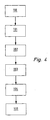
- Figure 1 shows a preferred embodiment of the device 11 according to the invention for monitoring the function of the fluid control valves 12, of which, for example, a 3/2-way valve is shown.
- the valve 12 is with a actuated actuator or actuator coupled exemplified in the form of a single-acting pneumatic cylinder 13 is shown with return spring.
- actuated actuator or actuator coupled exemplified in the form of a single-acting pneumatic cylinder 13 is shown with return spring.
- various types of actuators can be actuated by means of the valve 12.
- the valve 12 has an electric actuator 14 for valve actuation, which is exemplified in the form of an electromagnet.
- an electric actuator 14 for valve actuation which is exemplified in the form of an electromagnet.
- other types of electrical actuators are used, such as piezoelectric elements o. The like.
- the solenoid is used according to preferred embodiment for actuating a pilot valve 15, which in turn is used for pneumatic actuation of the actual main valve 30, for example, such that a drive piston of the main valve 30 by means Pressurization can be brought into different switching positions, so that thereby different valve channels can be connected to each other or separated from each other.
- a pilot valve 15 On the construction of the pilot and the main valve 15, 30 will not be discussed in more detail below.
- the electrical actuator 14 is coupled to an operating status indicator 16, which is exemplified by an LED.
- the operating state display 16 serves to display the current operating state of the electric actuator 14, for example in the form that illuminates the LED upon energization of the solenoid located in the solenoid and thus indicates a functional state, while the LED remains dark in the de-energized state of the solenoid coil.
- the device 11 for monitoring the operation of the valve 12 comprises an optical sensor 17, which is shown by way of example with reference to a photodiode.
- the photodiode is facing the operating state display 16 and is used for optical detection of a change in operating state of the electrical actuator 14.
- the optical sensor 17 is coupled to a signal processing device 18, which serves in the manner to be described in more detail below for signal processing of the transmitted signals from the optical sensor 17.
- the signal processing device 18 has an analysis unit 19, for example a display, on which various signals in the form of "peaks" can be displayed.
- a detection device 20 is provided which is attached to a pressure hose 40 connecting the valve outlet and the actuator.
- the detection device 20 includes a mounting clamp 21 which can be attached to the pressure hose 40.
- the mounting clamp 21 in turn has two clamping legs 22a, 22b, which can be clamped onto the pressure hose 40, wherein on a clamping leg 22b, an acceleration sensor 23 which measures a pressure change in the hose, which is accompanied by a change in diameter of the hose, and in the form of a Acceleration signal to the signal processing device 18 is transmitted.
- the piston chamber 24 of the compressed air cylinder 13 which can be acted upon by compressed air is vented by interconnecting the working connection "A" with the venting connection "R".
- the solenoid of the electromagnet is in the de-energized state.
- the LED is dark.
- the detection device 20, in particular its attachment clamp 21 is attached to the pressure hose 40.
- the optical sensor 17 is fixed, for example, with a clip or plasticine in the region of the LED.
- an operating state change of the solenoid is now brought about, for example, the solenoid of the electromagnet is energized.
- the voltage curve of the magnetic coil voltage 25 over time is shown in FIG. 3 by way of example with reference to the dashed line.
- the electromagnet is coupled to the LED so that it lights up when the solenoid is energized.
- the voltage curve of the LED voltage 26 over time is shown by way of example in FIG. 3 by the dot-dash line.
- the voltage jump at the LED is essentially instantaneous with respect to the voltage jump at the solenoid coil.
- the illumination of the LED which signals the operating state change of the electromagnet, is detected via the optical sensor 16 and converted into a signal, which is transmitted to the signal processing device 18 according to step 102.
- this signal is set as the start time t 0 .
- valve outlet will experience a pressure change which, according to step 103, is measured by means of the detection device 20, in particular with the acceleration sensor 23.
- the acceleration sensor 23 measures a diameter change of the pressure hose 40 caused by the pressure change over a certain time window. In the concrete case, the hose will therefore widen as a result of the pressure increase.
- An acceleration signal is generated, which is transmitted to the signal processing device 18, where it can be read, for example, at the analysis unit 19 in the form of a "peak".
- the switching state of the valve 12 is now verified. If no such "peak” is present, this is an indication that there is a malfunction of the valve 12, for example, that the valve 12 does not switch correctly despite energization of the solenoid. If a "peak” differs from the background noise, this is a sign that the valve 12 has switched.
Landscapes
- Engineering & Computer Science (AREA)
- General Engineering & Computer Science (AREA)
- Mechanical Engineering (AREA)
- Physics & Mathematics (AREA)
- Fluid Mechanics (AREA)
- Indication Of The Valve Opening Or Closing Status (AREA)
- Fluid-Pressure Circuits (AREA)
- Measuring Fluid Pressure (AREA)
Abstract
Description
Die Erfindung betrifft ein Verfahren und eine Vorrichtung zur Funktionsüberwachung bei der Fluidsteuerung dienenden Ventilen, die wenigstens ein elektrisches Betätigungsglied zur Ventilbetätigung aufweisen, das mit einer Betriebszustandsanzeige zur Anzeige des aktuellen Betriebszustands des Betätigungsglieds gekoppelt ist.The invention relates to a method and a device for monitoring function in the fluid control valves having at least one actuator for valve actuation, which is coupled to an operating state display for displaying the current operating state of the actuator.
Wie die meisten Bauteile in technischen Anlagen müssen auch Ventile von Zeit zu Zeit gewartet, überprüft oder repariert werden. Eine Möglichkeit den Funktionszustand des zu untersuchenden Ventils zu bestimmen, ist, zu messen ob das Ventil schaltet und falls ja, ob die Schaltzeit in einem vorgegebenen Rahmen bleibt. Diese sogenannten "Schaltzeitmessungen" sind relativ aufwendig, da das "Innenleben" der Ventile nicht ohne weiteres zugänglich ist und somit ein spezielles Mess-Equipment eingesetzt werden muss, dessen Bedienung jedoch ein geschultes Fachpersonal voraussetzt.Like most components in engineering plants, valves must be serviced, checked or repaired from time to time. One way to determine the functional state of the valve to be examined is to measure whether the valve switches and, if so, whether the switching time remains within a predetermined range. These so-called "switching time measurements" are relatively expensive, since the "inner life" of the valves is not readily accessible and thus a special measuring equipment must be used, the operation of which, however, requires a trained specialist staff.
Eine Möglichkeit an Apparaturen bzw. Anlagen während des Betriebs, "in-situ", zu messen, ist in der
In der
Die
Aufgabe der Erfindung ist es ein Verfahren und eine Vorrichtung zur Funktionsüberwachung bei Ventilen gemäß der eingangs erwähnten Art zu schaffen, die gegenüber herkömmlichen Methoden und Vorrichtungen einfacher und schneller handhabbar und somit kostengünstiger sind.The object of the invention is to provide a method and a device for monitoring the operation of valves of the type mentioned above, which are easier and faster to handle than conventional methods and devices and thus less expensive.
Diese Aufgabe wird durch ein Verfahren gemäß den Merkmalen des unabhängigen Anspruchs 1 und eine Vorrichtung gemäß den Merkmalen des unabhängigen Anspruchs 12 gelöst. Weiterbildungen der Erfindung sind in den Unteransprüchen dargestellt.This object is achieved by a method according to the features of independent claim 1 and an apparatus according to the features of
Das erfindungsgemäße Verfahren zeichnet sich dadurch aus, dass eine Änderung des angezeigten Betriebszustands des Betätigungsglieds mittels eines optischen Sensors optisch erfasst und die Betriebszustandsänderung als Startzeitpunkt t0 festgelegt wird. Am Ventilausgang bzw. Arbeitsanschluss wird eine Druckänderung als Folge der Betriebszustandsänderung mittels einer Erfassungseinrichtung ab dem Startzeitpunkt t0 gemessen und ein der Druckänderung zugeordnetes Signal erzeugt. Der Schaltzustand des Ventils wird verifiziert, wobei geprüft wird, ob nach einer bestimmten Zeit ab dem Startzeitpunkt t0 ein bestimmtes druckabhängiges Signal vorhanden ist.The inventive method is characterized in that a change of the displayed operating state of the actuator by means of an optical sensor is detected optically and the operating state change is set as the start time t 0 . At the valve outlet or working port, a pressure change is measured as a result of the operating state change by means of a detection device from the start time t 0 and generates a signal associated with the pressure change. The switching state of the valve is verified, being checked is whether after a certain time from the start time t 0, a certain pressure-dependent signal is present.
Die Schaltfunktion des zu untersuchenden Ventils kann überprüft werden, ohne in das "Innenleben" des Ventils selber eingreifen zu müssen, so dass derartige Messungen in einfacher Weise bei einem Serviceeinsatz oder auch im ständigen Betrieb als laufende Diagnose durchgeführt werden können.The switching function of the valve to be examined can be checked without having to intervene in the "inner life" of the valve itself, so that such measurements can be carried out in a simple manner in a service operation or in continuous operation as ongoing diagnosis.
Der Schaltzustand des Ventils kann qualitativ oder quantitativ bestimmt werden, wobei bei einer qualitativen Bestimmung ein Vorliegen eines bestimmten druckabhängigen Signals einem Schalten bzw. einem Schaltvorgang des Ventils und ein Nicht-Vorliegen eines bestimmten druckabhängigen Signals einer Fehlfunktion zugeordnet werden kann. Qualitativ kann also geprüft werden, ob ein bestimmtes druckabhängiges Signal vorliegt oder nicht. Liegt kein bestimmtes druckabhängiges, insbesondere gar kein Signal vor, kann dies mehrere Ursachen haben, beispielsweise kann es daran liegen, dass das Ventil nicht schaltet. Es ist jedoch auch möglich, dass der betreffende Ventilkanal verstopft ist oder dass Druckmedium bzw. Fluid gar nicht in den betreffenden Ventilkanal gelangt, sondern in andere Kanäle strömt oder möglicherweise aus dem Ventil entweicht. Jedenfalls ist das Nicht-Vorliegen eines bestimmten druckabhängigen Signals ein Anzeichen dafür, dass das zu untersuchende Ventil genauer überprüft und gegebenenfalls ausgetauscht werden muss.The switching state of the valve can be determined qualitatively or quantitatively, wherein in a qualitative determination, a presence of a specific pressure-dependent signal to a switching or switching operation of the valve and a non-existence of a specific pressure-dependent signal can be assigned to a malfunction. Qualitatively, it can therefore be checked whether a specific pressure-dependent signal is present or not. If there is no specific pressure-dependent, in particular no signal, this can have several causes, for example, it may be because the valve does not switch. However, it is also possible that the relevant valve channel is blocked or that pressure medium or fluid does not get into the relevant valve channel, but flows into other channels or possibly escapes from the valve. In any case, the absence of a specific pressure-dependent signal is an indication that the valve under test needs to be checked more closely and replaced if necessary.
Bei einer quantitativen Ermittlung des Ventil-Schaltzustands kann aus der Zeit zwischen dem Startzeitpunkt t0 und dem Vorliegen eines bestimmten druckabhängigen Signals eine Ist-Schaltzeit des Ventils ermittelt werden, die mit einer vorgegebenen Soll-Schaltzeit verglichen wird. Vorzugsweise wird eine Ist-Schaltzeit, die kleiner oder gleich der Soll-Schaltzeit ist, einem korrekten Schaltvorgang des Ventils zugeordnet. In bevorzugter Weise schließt sich an die qualitative Bestimmung des Schaltzustandes des Ventils die quantitative an und zwar in der Art, das bei Vorliegen eines bestimmten druckabhängigen Signals in einem nächsten Schritt geprüft wird, ob dieses Signal innerhalb des vorgegebenen Zeitfensters, also innerhalb der vorgegebenen Soll-Schaltzeit, liegt.In a quantitative determination of the valve switching state, an actual switching time of the valve can be determined from the time between the start time t 0 and the presence of a specific pressure-dependent signal, which is compared with a predetermined target switching time. Preferably, an actual switching time, which is less than or equal to the desired switching time, associated with a correct switching operation of the valve. Preferably, the qualitative determination of the switching state of the valve is followed by the quantitative in the manner that is checked in the presence of a certain pressure-dependent signal in a next step, whether this signal within the predetermined time window, ie within the predetermined target Switching time, is.
Es ist möglich die Ist-Schaltzeit mehrmals hintereinander zu bestimmen, um zu überprüfen, ob sich diese verändert, beispielsweise erhöht oder erniedrigt. Eine Veränderung, insbesondere Erhöhung der Ist-Schaltzeit kann auf Verschleiß des Ventils hindeuten, beispielsweise könnte bei Ventilen mit Ventilschiebern Reibverschleiß zwischen Ventilschieber und dem ihm umgebenden Gehäuse vorhanden sein.It is possible to determine the actual switching time several times in succession in order to check whether it changes, for example increases or decreases. A change, in particular increase of the actual switching time may indicate wear of the valve, for example, could be present in valves with valve spools Reibverschleiß between the valve spool and the surrounding housing.
Besonders bevorzugt wird vor der eigentlichen Messung zunächst bei konstantem Betriebszustand des Betätigungsglieds ein druckabhängiges Referenzsignal, beispielsweise ein Grundrauschen ermittelt. Dadurch kann beurteilt werden, dass ein ankommendes bestimmtes druckabhängiges Signal nicht zum Grundrauschen gehört, sondern bereits ein Messsignal darstellt.Particularly preferably, a pressure-dependent reference signal, for example a noise floor, is first determined at a constant operating state of the actuator before the actual measurement. As a result, it can be judged that an incoming specific pressure-dependent signal does not belong to the background noise but already represents a measurement signal.
Bei der Betriebszustandsanzeige kann es sich um eine Leuchtanzeige handeln, die vorzugsweise mittels Aufleuchten einen Funktionszustand und im dunklen Zustand einen Ruhezustand des Betätigungsglieds anzeigt. Selbstverständlich kann auch der Funktionszustand per ausgeschalteter Leuchtanzeige und der Ruhezustand per eingeschalteter Leuchtanzeige angezeigt werden. Ausschlaggebend ist, dass eine Betriebszustandsänderung durch den optischen Sensor erfasst werden kann. So ist es prinzipiell auch möglich den Funktionszustand durch ein helleres Leuchten und den Ruhezustand durch ein schwächeres Leuchten der Leuchtanzeige darzustellen oder umgekehrt.The operating state display may be a light-emitting display, which preferably displays a functional state by means of lighting and, in the dark state, an idle state of the actuating element. Of course, the functional state can also be displayed by the illuminated indicator and the idle state by the illuminated indicator. The decisive factor is that an operating state change can be detected by the optical sensor. So it is in principle also possible to represent the functional state by a brighter light and the idle state by a weaker illumination of the light indicator or vice versa.
Eine andere Möglichkeit ist, den Betriebszustand des Betätigungsglieds mittels Symbolen anzuzeigen, vorzugsweise durch Schrift, beispielsweise durch Anzeigen von "on" für den Funktionszustand und "off" für den Ruhezustand. Auch hier könnte ein Wechsel zwischen "off" und "on" mittels des optischen Sensors detektiert werden.Another possibility is to indicate the operating state of the actuator by means of symbols, preferably by writing, for example by displaying "on" for the functional state and "off" for the idle state. Again, a change between "off" and "on" could be detected by means of the optical sensor.
Zweckmäßigerweise handelt es sich bei der Leuchtanzeige um wenigstens ein Leuchtmittel, beispielsweise um wenigsten eine LED. Alternativ oder zusätzlich ist auch ein Leuchtmittel in Form einer Glühbirne möglich.Expediently, the illuminated display is at least one luminous means, for example at least one LED. Alternatively or additionally, a light bulb in the form of a light bulb is possible.
Bei einer Weiterbildung der Erfindung handelt es sich bei dem optischen Sensor um ein optisch empfindliches Halbleiterelement, beispielsweise um eine Fotodiode und/oder einen Fototransistor.In a development of the invention, the optical sensor is an optically sensitive semiconductor element, for example a photodiode and / or a phototransistor.
Der optische Sensor kann mit einer Signalverarbeitungseinrichtung gekoppelt sein, die ein infolge der Betriebszustandsänderung des Betätigungsglieds vom optischen Sensor initiiertes Signal verarbeitet und dieses Signal als Startzeitpunkt t0 festlegt. Ferner kann in der Signalverarbeitungseinrichtung das von der Erfassungseinrichtung übermittelte druckabhängige Signal verarbeitet werden. Als Signalverarbeitungseinrichtung ist vorzugsweise ein Rechner mit einem Mikro-Controller vorgesehen. Der Mikro-Controller kann dabei so ausgelegt sein, dass ein beim Messen erzeugtes bestimmtes druckabhängiges Signal selbstständig vom insbesondere vorher hinterlegten Referenzsignal bzw. vom Grundrauschen unterschieden wird. Zweckmäßigerweise besitzt die Signalverarbeitungseinrichtung eine Analyseeinheit anhand derer die Messergebnisse ausgewertet werden können. Beispielsweise kann ein Display vorgesehen sein, auf dem die druckabhängigen Signale als "Peaks" zu sehen sind.The optical sensor can be coupled to a signal processing device which processes a signal initiated by the optical sensor as a result of the operating state change of the actuator and determines this signal as start time t 0 . Furthermore, the pressure-dependent signal transmitted by the detection device can be processed in the signal processing device. As a signal processing device, a computer with a micro-controller is preferably provided. The microcontroller can be designed so that a specific pressure-dependent signal generated during the measurement is distinguished independently from the particular previously stored reference signal or from the background noise. Expediently, the signal processing device has an analysis unit by means of which the measurement results can be evaluated. For example, a display may be provided on which the pressure-dependent signals are to be seen as "peaks".
Besonders bevorzugt kann die Erfassungseinrichtung an der Ventilperipherie des zu untersuchenden Ventil lösbar befestigt werden, insbesondere an einem mit dem Ventilausgang bzw. Arbeitsanschluss verbundenen Druckschlauch. Dadurch ist es möglich eine zu erwartende Druckänderung im Schlauch "in-situ" bzw. während des Ventilbetriebs zu messen. Eine Druckänderung wird vorzugsweise in Form eines Beschleunigungssignal mittels eines der Erfassungseinrichtung zugeordneten Beschleunigungssensors erfasst. Vorzugsweise ist der Beschleunigungssensor Teil der Erfassungseinrichtung, beispielsweise derart, dass eine Schlauchklemme verwendet wird, in die der in der Regel kapazitiv arbeitende Beschleunigungssensor integriert ist.Particularly preferably, the detection device can be detachably fastened to the valve periphery of the valve to be examined, in particular to a pressure hose connected to the valve outlet or working connection. This makes it possible to measure an expected pressure change in the hose "in-situ" or during valve operation. A pressure change is preferably detected in the form of an acceleration signal by means of an acceleration sensor assigned to the detection device. Preferably, the acceleration sensor is part of the detection device, for example, such that a hose clamp is used, in which the usually capacitive acceleration sensor is integrated.
Prinzipiell ist es auch möglich den Druck mit einem Drucksensor zu messen, beispielsweise derart, dass der Drucksensor in den Arbeitskanal oder Druckschlauch integriert wird. Der Drucksensor kann beispielsweise in ein T-Stück eingebaut werden, das nachträglich an den Arbeitskanal angebaut wird. Alternativ kann sich das T-Stück bereits am Arbeitskanal befinden, wodurch lediglich noch der Drucksensor einzubauen ist.In principle, it is also possible to measure the pressure with a pressure sensor, for example, such that the pressure sensor is integrated into the working channel or pressure hose. The pressure sensor can be installed, for example, in a T-piece, which is subsequently attached to the working channel. Alternatively, the T-piece may already be on the working channel, whereby only the pressure sensor is to be installed.
Es ist möglich, dass bei Vorliegen eines druckabhängigen Signals eine Bestätigung in Form eines optischen und/oder akustischen Signals erfolgt, beispielsweise durch Aufblinken einer Leuchtanzeige und/oder durch Ertönen eines Pieps- oder Pfeiftons.It is possible that in the presence of a pressure-dependent signal confirmation in the form of an optical and / or acoustic signal, for example by flashing a light indicator and / or by sounding a beep or whistle.
Die Erfindung umfasst ferner eine Vorrichtung zur Funktionsüberwachung bei der Fluidsteuerung dienenden Ventilen, die sich dadurch auszeichnet, dass ein optischer Sensor zur optischen Erfassung einer Änderung des angezeigten Betriebszustandes des Betätigungsglieds vorgesehen ist, der mit einer Signalverarbeitungseinrichtung zur Verarbeitung des vom optischen Sensor übermittelten Signals und zur Festlegung der Betriebszustandsänderung als Startzeitpunkt t0 gekoppelt ist. Es ist eine Erfassungseinrichtung zur Messung einer Druckänderung am Ventilausgang als Folge der Betriebszustandsänderung vorgesehen, die ein druckabhängiges Signal, das der Druckänderung zugeordnet ist, an die Signalverarbeitungseinrichtung übermittelt. Die Signalverarbeitungseinrichtung besitzt eine Analyseeinheit, um den Schaltzustand des Ventils zu verifizieren, wobei geprüft wird, ob ein bestimmtes druckabhängiges Signal ab dem Startzeitpunkt t0 vorliegt.The invention further comprises a device for monitoring the operation of the fluid control valves, which is characterized in that an optical sensor for optically detecting a change in the displayed operating state of the actuator is provided with a signal processing means for processing the signal transmitted from the optical sensor and the Determining the operating state change is coupled as start time t 0 . A detection device is provided for measuring a pressure change at the valve outlet as a result of the operating state change, which is a pressure-dependent signal, which is associated with the pressure change, to the signal processing device transmitted. The signal processing device has an analysis unit to verify the switching state of the valve, wherein it is checked whether a certain pressure-dependent signal from the start time t 0 is present.
Bezüglich weiterer Details der erfindungsgemäßen Vorrichtung wird auf die vorstehende Beschreibung und die nachfolgende Beschreibung eines bevorzugten Ausführungsbeispiels verwiesen.For further details of the device according to the invention, reference is made to the above description and the following description of a preferred embodiment.
Ein bevorzugtes Ausführungsbeispiel ist in den Zeichnungen dargestellt und wird im folgenden näher erläutert. Die Zeichnungen zeigen:
- Figur 1
- eine schematische Übersichtsdarstellung der erfindungsgemäßen Vorrichtung,
- Figur 2
- eine Seitenansicht auf eine an einem Druckschlauch befestigte Erfassungsvorrichtung,
- Figur 3
- den Spannungs- bzw. Druckverlauf über der Zeit bei einem Messvorgang an einem Ventil und
- Figur 4
- ein schematisches Blockschaubild zur Veranschaulichung des erfindungsgemäßen Verfahrens.
- FIG. 1
- a schematic overview of the device according to the invention,
- FIG. 2
- a side view of a mounted on a pressure hose detection device,
- FIG. 3
- the voltage or pressure curve over time in a measuring operation on a valve and
- FIG. 4
- a schematic block diagram illustrating the method according to the invention.
Figur 1 zeigt ein bevorzugtes Ausführungsbeispiel der erfindungsgemäßen Vorrichtung 11 zur Funktionsüberwachung von der Fluidsteuerung dienenden Ventilen 12, von denen beispielhaft ein 3/2-Wegeventil dargestellt ist. Das Ventil 12 ist mit einem zu betätigenden Antriebsglied bzw. Aktor gekoppelt das beispielhaft in Form eines einfach wirkenden Druckluftzylinders 13 mit Rückstellfeder dargestellt ist. Selbstverständlich können verschiedenste Arten von Aktoren mittels des Ventils 12 betätigt werden.Figure 1 shows a preferred embodiment of the
Das Ventil 12 besitzt ein elektrisches Betätigungsglied 14 zur Ventilbetätigung, das beispielhaft in Form eines Elektromagneten dargestellt ist. Prinzipiell sind auch andere Arten von elektrischen Betätigungsgliedern einsetzbar, beispielsweise Piezoelemente o. dgl. Der Elektromagnet dient gemäß bevorzugtem Ausführungsbeispiel zur Betätigung eines Vorsteuerventils 15, das seinerseits zur pneumatischen Betätigung des eigentlichen Hauptventils 30 eingesetzt wird, beispielsweise derart, dass ein Antriebskolben des Hauptventils 30 mittels Druckbeaufschlagung in verschiedene Schaltstellungen gebracht werden kann, so dass dadurch verschiedene Ventilkanäle miteinander verbunden oder voneinander getrennt werden können. Auf den Aufbau des Vorsteuer- und des Hauptventils 15, 30 soll im folgenden nicht näher eingegangen werden.The
Das elektrische Betätigungsglied 14 ist mit einer Betriebszustandsanzeige 16 gekoppelt, die beispielhaft anhand einer LED dargestellt ist. Die Betriebszustandsanzeige 16 dient zur Anzeige des aktuellen Betriebszustandes des elektrischen Betätigungsglieds 14, beispielsweise in der Form, das bei einer Erregung der im Elektromagneten befindlichen Magnetspule die LED aufleuchtet und somit einen Funktionszustand anzeigt, während die LED im unerregten Zustand der Magnetspule dunkel bleibt.The
Die Vorrichtung 11 zur Funktionsüberwachung des Ventils 12 umfasst einen optischen Sensor 17, der beispielhaft anhand einer Fotodiode dargestellt ist. Die Fotodiode ist der Betriebszustandsanzeige 16 zugewandt und dient zur optischen Erfassung einer Betriebszustandsänderung des elektrischen Betätigungsglieds 14. Der optische Sensor 17 ist mit einer Signalverarbeitungseinrichtung 18 gekoppelt, die in nachfolgend näher zu schildernden Weise zur Signalverarbeitung der vom optischen Sensor 17 übermittelten Signale dient. Die Signalverarbeitungseinrichtung 18 besitzt eine Analyseeinheit 19 beispielsweise ein Display, auf der verschiedene Signale in Form von "Peaks" angezeigt werden können.The
Es ist ferner eine Erfassungseinrichtung 20 vorgesehen, die an einem den Ventilausgang und den Aktor verbindenden Druckschlauch 40 angebracht ist. Wie in Figur 3 dargestellt, umfasst die Erfassungsvorrichtung 20 eine Befestigungsklemme 21, die am Druckschlauch 40 befestigt werden kann. Die Befestigungsklemme 21 besitzt ihrerseits zwei Klemmschenkel 22a, 22b, die auf den Druckschlauch 40 geklemmt werden können, wobei sich an einem Klemmschenkel 22b ein Beschleunigungssensor 23 befindet, der eine Druckänderung im Schlauch, die mit einer Durchmesseränderung des Schlauchs einhergeht, misst und in Form eines Beschleunigungssignals an die Signalverarbeitungseinrichtung 18 übermittelt.Furthermore, a
Im Folgenden wird das erfindungsgemäße Verfahren beispielhaft anhand einer Funktionsüberwachung eines 3/2-Wegeventils beschrieben, das zur Fluidsteuerung eines einfach wirkenden Druckluftzylinder 13 dient.In the following, the method according to the invention will be described by way of example with reference to a function monitoring of a 3/2-way valve which serves to control the fluid of a single-acting
Wie in Figur 1 dargestellt und in Figur 4 durch den Schritt 100 repräsentiert, ist die mit Druckluft beaufschlagbare Kolbenkammer 24 des Druckluftzylinders 13 durch Zusammenschaltung des Arbeitsanschlusses "A" mit dem Entlüftungsanschluss "R" entlüftet. Die Magnetspule des Elektromagneten ist im unerregten Zustand. Die LED ist dunkel. Die Erfassungseinrichtung 20, insbesondere deren Befestigungsklemme 21 ist am Druckschlauch 40 befestigt. Der optische Sensor 17 ist beispielsweise mit einem Clip oder Knetmasse im Bereich der LED festgelegt. Gemäß Schritt 101 wird nun eine Betriebszustandsänderung der Magnetspule herbeigeführt, beispielsweise wird die Magnetspule des Elektromagneten mit Strom beaufschlagt. Der Spannungsverlauf der Magnetspulenspannung 25 über der Zeit ist in Figur 3 beispielhaft anhand der gestrichelten Linie dargestellt. Beim Erregen der Magnetspule kommt es zu einem Spannungssprung, das heißt die Spannung wird schlagartig größer. Der Elektromagnet ist mit der LED gekoppelt, so dass diese bei Erregung der Magnetspule aufleuchtet. Der Spannungsverlauf der LED-Spannung 26 über der Zeit ist in Figur 3 beispielhaft durch die strichpunktierte Linie dargestellt. Der Spannungssprung an der LED erfolgt im Wesentlichen verzögerungsfrei gegenüber dem Spannungssprung an der Magnetspule.As represented in FIG. 1 and represented by
Das Aufleuchten der LED, das die Betriebszustandsänderung des Elektromagneten signalisiert, wird über den optischen Sensor 16 detektiert und in ein Signal umgewandelt, das gemäß Schritt 102 an die Signalverarbeitungseinrichtung 18 übermittelt wird. In der Signalverarbeitungseinrichtung 18 wird dieses Signal als Startzeitpunkt t0 festgelegt.The illumination of the LED, which signals the operating state change of the electromagnet, is detected via the
Durch die Erregung der Magnetspule wird es im Normalfall zu einem Schaltvorgang des Ventils 12 kommen, wodurch der Speisenanschluss "P" mit dem Arbeitsanschluss "A" verbunden wird, so dass Druckluft in die Kolbenkammer 24 des Druckluftzylinders strömen kann. Ist dies der Fall, müsste am Ventilausgang eine Druckänderung, insbesondere eine Druckerhöhung feststellbar sein. Der Druckverlauf am Ventilausgang 27 über der Zeit ist in Figur 3 mittels der gepunkteten Linie dargestellt. Da die Kolbenkammer 24 im vorausgegangenen Schaltzustand entlüftet war, braucht es im Regelfall eine gewisse Zeit, bis ein Druckanstieg detektiert werden kann, da sich die Kolbenkammer erst noch mit Druckluft füllen muss. Dies ist beispielhaft daran zu erkennen, dass ein detektiertes druckabhängiges Signal 28, das beispielhaft mittels der durchgezogenen Linie in Figur 3 dargestellt ist, erst mit Verzögerung dem Spannungssprung an der Magnetspule bzw. an der LED folgt.The excitation of the solenoid coil will normally cause a switching operation of the
Schaltet das Ventil 12 also korrekt in seinen zweiten Schaltzustand, so kommt es am Ventilausgang zu einer Druckänderung, die gemäß Schritt 103 mittels der Erfassungseinrichtung 20, insbesondere mit dem Beschleunigungssensor 23 gemessen wird.Thus, if the
Der Beschleunigungssensor 23 misst eine durch die Druckänderung verursachte Durchmesseränderung des Druckschlauchs 40 über ein bestimmtes Zeitfenster. Im konkreten Fall wird sich der Schlauch also in Folge der Druckerhöhung aufweiten. Es wird ein Beschleunigungssignal erzeugt, das an die Signalverarbeitungseinrichtung 18 übermittelt wird, wo es beispielsweise an der Analyseeinheit 19 in Form eines "Peaks" abgelesen werden kann. Gemäß Schritt 104 wird nun der Schaltzustand des Ventils 12 verifiziert. Ist kein solcher "Peak" vorhanden, ist dies ein Anzeichen dafür, dass eine Fehlfunktion des Ventils 12 vorliegt, beispielsweise dass das Ventil 12 trotz Erregung der Magnetspule nicht korrekt schaltet. Kommt ein "Peak" an, der sich vom Grundrauschen unterscheidet, so ist das ein Zeichen dafür, dass das Ventil 12 geschaltet hat.The
Gemäß Schritt 105 kann noch zusätzlich aus der Zeit zwischen dem Startzeitpunkt t0 und dem Auftauchen des "Peaks" die Schaltzeit ts für das Ventil 12 bestimmt werden, wobei die Schaltzeit ts die Differenz ts=t1-t0 ist. Weicht diese Ist-Schaltzeit von einer vorgegebenen, insbesondere in der Signalverarbeitungseinrichtung 18 gespeicherten Soll-Schaltzeit ab, so muss das Ventil 12 gewartet werden. Durch mehrmalige Bestimmung der Ist-Schaltzeit hintereinander, lässt sich feststellen, ob sich diese mit der Zeit verändert, insbesondere erhöht, was für einen Verschleiß des Ventils 12 spricht.According to step 105, the switching time t s for the
Claims (23)
- Method for monitoring the function of valves (12) used for fluid control, which comprise at least one electric actuating element (14) for valve actuation, said method being coupled to an operating state indicator (16) for the indication of the current operating state of the actuating element (14) and comprising the following steps:- optical detection of a change in the indicated operating state by means of an optical sensor (17),- definition of the change in operating state as starting time t0,- measurement of a pressure change at the valve outlet resulting from the change in operating state by means of a detection device (20) from the starting time to and generation of a pressure-dependent signal (28) assigned to the pressure change, and- verification of the switching state of the valve by checking for the presence of a defined pressure-dependent signal (28) at a defined time from the starting time to.
- Method according to claim 1, characterised in that a presence of a defined pressure-dependent signal (28) is assigned to a switching action of the valve (10) and an absence of a defined pressure-dependent signal (28) is assigned to a malfunction, in particular to a lack of a switching action, of the valve (12).
- Method according to claim 1 or 2, characterised in that an actual switching time of the valve, which is compared to a predetermined set switching time, is determined from the time elapsed between the starting time to and the presence of a defined pressure-dependent signal (28), the case in which the actual switching time is shorter than or equal to the set switching time being assigned to the correct switching action of the valve (12).
- Method according to claim 3, characterised in that the actual switching time is determined several times in succession in order to check whether it changes.
- Method according to any of the preceding claims, characterised in that, in a constant operating state of the electric actuating element (14), a pressure-dependent reference signal, for example a background noise, is first determined and a detected defined pressure-dependent signal (28) is compared to the reference signal.
- Method according to any of the preceding claims, characterised in that the operating state indicator (16) is an illuminated display which preferably indicates an operative state of the actuating element (14) by illuminating and a non-operative state by extinguishing.
- Method according to claim 6, characterised in that the illuminated display comprises at least one light-emitting means, in particular an LED.
- Method according to any of the preceding claims, characterised in that the optical sensor (17) is an optically sensitive semiconductor element, preferably with a sensitivity in the visible range.
- Method according to claim 8, characterised in that the semiconductor element is a photo diode and/or a photo transistor.
- Method according to any of the preceding claims, characterised in that the detection device (20) can be releasably secured to the periphery of the valve (12) to be checked, in particular to a pressure hose (40) connected to the relevant valve outlet.
- Method according to any of the preceding claims, characterised in that the pressure-dependent signal (28) is an acceleration signal detected by means of an acceleration sensor (23) assigned to the detection device (20).
- Device for monitoring the function of valves (12) used for fluid control, which comprise at least one electric actuating element (14) for valve actuation, said device comprising an operating state indicator (16) coupled to the actuating element for the indication of the current operating state of the actuating element (14), characterised in that the device comprises an optical sensor (17) for the optical detection of a change in the indicated operating state of the actuating element (14), which is coupled to a signal processing device (18) of the device for processing the signals transmitted by the optical sensor and for defining the change in operating state as starting time t0,
wherein the device comprises a detection device (20) for measuring a pressure change at the valve outlet resulting from the change in operating state from the starting time t0, for generating a pressure-dependent signal (28) assigned to the pressure change and for transmitting this signal to the signal processing device (18), wherein the signal processing device (18) comprises an analysis unit (19) for verifying the switching state of the valve such that the presence of a defined pressure-dependent signal (28) from the starting time to can be checked. - Device according to claim 12, characterised in that an illuminated display which preferably indicates an operative state of the actuating element (14) by illuminating and a non-operative state by extinguishing is provided as an operating state indicator (16).
- Device according to claim 13, characterised in that at least one light-emitting means, in particular an LED, is provided as an illuminated display.
- Device according to any of claims 12 to 14, characterised in that an optically sensitive semiconductor element, preferably with a sensitivity in the visible range, is provided as an optical sensor (17).
- Device according to claim 15, characterised in that a photo diode and/or a photo transistor are/is provided as a semiconductor element.
- Device according to any of claims 12 to 16, characterised in that the detection device (20) can be releasably secured to the periphery of the valve (12) to be checked, in particular to a pressure hose (40) connected to the valve outlet.
- Device according to any of claims 12 to 17, characterised in that the detection device (20) comprises at least one acceleration sensor (23) for detecting a pressure-dependent signal (28) in the form of an acceleration signal.
- Device according to claim 18, characterised in that the detection device (20) comprises a fixing clamp (21) integrated into the acceleration sensor (23).
- Device according to any of claims 12 to 17, characterised in that the detection device (20) comprises at least one pressure sensor for the detection of the pressure-dependent signal.
- Device according to any of claims 12 to 20, characterised in that a computer with a micro-controller is provided as a signal processing device (18).
- Device according to any of claims 12 to 21, characterised in that a solenoid with at least one coil is provided as an electric actuating element (14).
- Device according to any of claims 12 to 22, suitable for the method according to any of claims 1 to 11.
Applications Claiming Priority (2)
| Application Number | Priority Date | Filing Date | Title |
|---|---|---|---|
| DE102004001915 | 2004-01-14 | ||
| DE102004001915A DE102004001915B3 (en) | 2004-01-14 | 2004-01-14 | Method and device for monitoring the function of valves |
Publications (2)
| Publication Number | Publication Date |
|---|---|
| EP1555472A1 EP1555472A1 (en) | 2005-07-20 |
| EP1555472B1 true EP1555472B1 (en) | 2007-12-19 |
Family
ID=34609534
Family Applications (1)
| Application Number | Title | Priority Date | Filing Date |
|---|---|---|---|
| EP04029305A Expired - Lifetime EP1555472B1 (en) | 2004-01-14 | 2004-12-10 | Process and apparatus for monitoring the functioning of valves |
Country Status (3)
| Country | Link |
|---|---|
| EP (1) | EP1555472B1 (en) |
| AT (1) | ATE381691T1 (en) |
| DE (2) | DE102004001915B3 (en) |
Cited By (1)
| Publication number | Priority date | Publication date | Assignee | Title |
|---|---|---|---|---|
| DE102022213928A1 (en) * | 2022-12-19 | 2024-06-20 | Robert Bosch Gesellschaft mit beschränkter Haftung | Method for operating an actuating device |
Families Citing this family (5)
| Publication number | Priority date | Publication date | Assignee | Title |
|---|---|---|---|---|
| US10442422B2 (en) * | 2017-12-22 | 2019-10-15 | Goodrich Corporation | Systems and methods for monitoring a health status of a servo valve |
| DE102018119798A1 (en) * | 2018-08-15 | 2020-02-20 | Fogtec Brandschutz Gmbh & Co. Kg | Method of monitoring valves |
| DE102019135575A1 (en) * | 2019-12-20 | 2021-06-24 | Bürkert Werke GmbH & Co. KG | Valve terminal with diagnostic module |
| DE102020201300B4 (en) | 2020-02-04 | 2022-06-02 | Festo Se & Co. Kg | pneumatic system |
| DE102020114408A1 (en) | 2020-05-28 | 2021-12-02 | Bürkert Werke GmbH & Co. KG | Diagnostic procedure for a process valve, diagnostic module and process valve |
Family Cites Families (8)
| Publication number | Priority date | Publication date | Assignee | Title |
|---|---|---|---|---|
| US4816987A (en) * | 1985-06-28 | 1989-03-28 | Electric Power Research Institute, Inc. | Microprocessor-based control and diagnostic system for motor operated valves |
| US4896101A (en) * | 1986-12-03 | 1990-01-23 | Cobb Harold R W | Method for monitoring, recording, and evaluating valve operating trends |
| US5202673A (en) * | 1989-09-19 | 1993-04-13 | Valve Security Systems, Inc. | Security method and apparatus |
| DE4439230C2 (en) * | 1994-11-03 | 1996-08-14 | Ingenieure Prof Sturm & Partne | Device and method for determining the condition of fittings |
| US5826616A (en) * | 1996-11-19 | 1998-10-27 | Isi Norgren, Inc. | Valve spool position detector apparatus |
| EP0962685B1 (en) * | 1998-06-03 | 2004-03-17 | Maquet Critical Care AB | Valve arrangement |
| GB2372087A (en) * | 2001-02-07 | 2002-08-14 | Drallim Ltd | Testing an emergency valve |
| US6523414B1 (en) * | 2001-04-16 | 2003-02-25 | Zevex, Inc. | Optical pressure monitoring system |
-
2004
- 2004-01-14 DE DE102004001915A patent/DE102004001915B3/en not_active Expired - Fee Related
- 2004-12-10 DE DE502004005747T patent/DE502004005747D1/en not_active Expired - Lifetime
- 2004-12-10 EP EP04029305A patent/EP1555472B1/en not_active Expired - Lifetime
- 2004-12-10 AT AT04029305T patent/ATE381691T1/en not_active IP Right Cessation
Cited By (1)
| Publication number | Priority date | Publication date | Assignee | Title |
|---|---|---|---|---|
| DE102022213928A1 (en) * | 2022-12-19 | 2024-06-20 | Robert Bosch Gesellschaft mit beschränkter Haftung | Method for operating an actuating device |
Also Published As
| Publication number | Publication date |
|---|---|
| EP1555472A1 (en) | 2005-07-20 |
| DE102004001915B3 (en) | 2005-11-03 |
| ATE381691T1 (en) | 2008-01-15 |
| DE502004005747D1 (en) | 2008-01-31 |
Similar Documents
| Publication | Publication Date | Title |
|---|---|---|
| DE10142790B4 (en) | Brake diagnostics for rail and road vehicles | |
| DE102011075935B4 (en) | Determination of functional states of an electromagnetic actuator | |
| EP2321563B1 (en) | Automated valve testing apparatus | |
| DE102012016295B4 (en) | Device and method for quantifying a leakage flow rate on an actuator | |
| EP3546763B1 (en) | Detection of maintenance conditions of valves | |
| EP0284785A1 (en) | Method and device for controlling the thightness of two valves successively disposed on a fluid conduit | |
| EP1555472B1 (en) | Process and apparatus for monitoring the functioning of valves | |
| US20100037966A1 (en) | Method for checking the functionality of an actuator | |
| US7210338B2 (en) | Valve testing device having integrated purge circuit and method of valve testing | |
| EP1184826A2 (en) | Device for the functional testing of a temperature sensor in a detector | |
| EP0840865A1 (en) | Automatic air-vent valve for hydraulic systems | |
| WO2001042693A2 (en) | Pressure relief valve detection and monitoring device and system | |
| EP1338237B1 (en) | Method and apparatus for testing the patency of endoscope channels | |
| EP3784937B1 (en) | Method for monitoring the function of a control valve, device for carrying out a method of this kind and control valve having a device of this kind | |
| JPH06294708A (en) | Method and system for testing durability of operating pedal | |
| WO2024033072A1 (en) | Abs control valve and method for testing the function of this abs control valve | |
| DE2544809B2 (en) | Insertion gauge for measuring the inside diameter of a container opening | |
| DE102006059938B3 (en) | Actuator diagnosing method for automating- and process technique, involves supplying emergency current with help of input converter, and actuating input converter against direction of action of signal flow as sensor | |
| CN103411024B (en) | Automated valve testing apparatus | |
| EP2432982B1 (en) | Method for measuring the armature lift in a fuel injector | |
| US12110886B2 (en) | Piston monitoring assembly | |
| DE102004012802B4 (en) | Method for testing errors in a drive unit of an injection molding machine | |
| DE69823687T2 (en) | METHOD AND DEVICE FOR CONTROLLING A PNEUMATICALLY ACTUATED VALVE | |
| DE102007042757A1 (en) | Method and device for indicating the position of hydraulically actuated valves | |
| DE102005031552B4 (en) | Procedure for operational testing of a measuring device |
Legal Events
| Date | Code | Title | Description |
|---|---|---|---|
| PUAI | Public reference made under article 153(3) epc to a published international application that has entered the european phase |
Free format text: ORIGINAL CODE: 0009012 |
|
| AK | Designated contracting states |
Kind code of ref document: A1 Designated state(s): AT BE BG CH CY CZ DE DK EE ES FI FR GB GR HU IE IS IT LI LT LU MC NL PL PT RO SE SI SK TR |
|
| AX | Request for extension of the european patent |
Extension state: AL BA HR LV MK YU |
|
| 17P | Request for examination filed |
Effective date: 20050603 |
|
| AKX | Designation fees paid |
Designated state(s): AT BE BG CH CY CZ DE DK EE ES FI FR GB GR HU IE IS IT LI LT LU MC NL PL PT RO SE SI SK TR |
|
| GRAP | Despatch of communication of intention to grant a patent |
Free format text: ORIGINAL CODE: EPIDOSNIGR1 |
|
| GRAS | Grant fee paid |
Free format text: ORIGINAL CODE: EPIDOSNIGR3 |
|
| GRAA | (expected) grant |
Free format text: ORIGINAL CODE: 0009210 |
|
| AK | Designated contracting states |
Kind code of ref document: B1 Designated state(s): AT BE BG CH CY CZ DE DK EE ES FI FR GB GR HU IE IS IT LI LT LU MC NL PL PT RO SE SI SK TR |
|
| REG | Reference to a national code |
Ref country code: GB Ref legal event code: FG4D Free format text: NOT ENGLISH |
|
| REG | Reference to a national code |
Ref country code: IE Ref legal event code: FG4D Free format text: LANGUAGE OF EP DOCUMENT: GERMAN |
|
| REG | Reference to a national code |
Ref country code: CH Ref legal event code: EP |
|
| REF | Corresponds to: |
Ref document number: 502004005747 Country of ref document: DE Date of ref document: 20080131 Kind code of ref document: P |
|
| PG25 | Lapsed in a contracting state [announced via postgrant information from national office to epo] |
Ref country code: SE Free format text: LAPSE BECAUSE OF FAILURE TO SUBMIT A TRANSLATION OF THE DESCRIPTION OR TO PAY THE FEE WITHIN THE PRESCRIBED TIME-LIMIT Effective date: 20080319 |
|
| PG25 | Lapsed in a contracting state [announced via postgrant information from national office to epo] |
Ref country code: LT Free format text: LAPSE BECAUSE OF FAILURE TO SUBMIT A TRANSLATION OF THE DESCRIPTION OR TO PAY THE FEE WITHIN THE PRESCRIBED TIME-LIMIT Effective date: 20071219 Ref country code: PL Free format text: LAPSE BECAUSE OF FAILURE TO SUBMIT A TRANSLATION OF THE DESCRIPTION OR TO PAY THE FEE WITHIN THE PRESCRIBED TIME-LIMIT Effective date: 20071219 Ref country code: NL Free format text: LAPSE BECAUSE OF FAILURE TO SUBMIT A TRANSLATION OF THE DESCRIPTION OR TO PAY THE FEE WITHIN THE PRESCRIBED TIME-LIMIT Effective date: 20071219 Ref country code: FI Free format text: LAPSE BECAUSE OF FAILURE TO SUBMIT A TRANSLATION OF THE DESCRIPTION OR TO PAY THE FEE WITHIN THE PRESCRIBED TIME-LIMIT Effective date: 20071219 Ref country code: SI Free format text: LAPSE BECAUSE OF FAILURE TO SUBMIT A TRANSLATION OF THE DESCRIPTION OR TO PAY THE FEE WITHIN THE PRESCRIBED TIME-LIMIT Effective date: 20071219 |
|
| NLV1 | Nl: lapsed or annulled due to failure to fulfill the requirements of art. 29p and 29m of the patents act | ||
| GBV | Gb: ep patent (uk) treated as always having been void in accordance with gb section 77(7)/1977 [no translation filed] | ||
| PG25 | Lapsed in a contracting state [announced via postgrant information from national office to epo] |
Ref country code: ES Free format text: LAPSE BECAUSE OF FAILURE TO SUBMIT A TRANSLATION OF THE DESCRIPTION OR TO PAY THE FEE WITHIN THE PRESCRIBED TIME-LIMIT Effective date: 20080330 Ref country code: IS Free format text: LAPSE BECAUSE OF FAILURE TO SUBMIT A TRANSLATION OF THE DESCRIPTION OR TO PAY THE FEE WITHIN THE PRESCRIBED TIME-LIMIT Effective date: 20080419 Ref country code: CZ Free format text: LAPSE BECAUSE OF FAILURE TO SUBMIT A TRANSLATION OF THE DESCRIPTION OR TO PAY THE FEE WITHIN THE PRESCRIBED TIME-LIMIT Effective date: 20071219 |
|
| PG25 | Lapsed in a contracting state [announced via postgrant information from national office to epo] |
Ref country code: RO Free format text: LAPSE BECAUSE OF FAILURE TO SUBMIT A TRANSLATION OF THE DESCRIPTION OR TO PAY THE FEE WITHIN THE PRESCRIBED TIME-LIMIT Effective date: 20071219 Ref country code: SK Free format text: LAPSE BECAUSE OF FAILURE TO SUBMIT A TRANSLATION OF THE DESCRIPTION OR TO PAY THE FEE WITHIN THE PRESCRIBED TIME-LIMIT Effective date: 20071219 |
|
| PG25 | Lapsed in a contracting state [announced via postgrant information from national office to epo] |
Ref country code: PT Free format text: LAPSE BECAUSE OF FAILURE TO SUBMIT A TRANSLATION OF THE DESCRIPTION OR TO PAY THE FEE WITHIN THE PRESCRIBED TIME-LIMIT Effective date: 20080519 |
|
| REG | Reference to a national code |
Ref country code: IE Ref legal event code: FD4D |
|
| EN | Fr: translation not filed | ||
| PLBE | No opposition filed within time limit |
Free format text: ORIGINAL CODE: 0009261 |
|
| STAA | Information on the status of an ep patent application or granted ep patent |
Free format text: STATUS: NO OPPOSITION FILED WITHIN TIME LIMIT |
|
| PG25 | Lapsed in a contracting state [announced via postgrant information from national office to epo] |
Ref country code: DK Free format text: LAPSE BECAUSE OF FAILURE TO SUBMIT A TRANSLATION OF THE DESCRIPTION OR TO PAY THE FEE WITHIN THE PRESCRIBED TIME-LIMIT Effective date: 20071219 Ref country code: IE Free format text: LAPSE BECAUSE OF FAILURE TO SUBMIT A TRANSLATION OF THE DESCRIPTION OR TO PAY THE FEE WITHIN THE PRESCRIBED TIME-LIMIT Effective date: 20071219 |
|
| 26N | No opposition filed |
Effective date: 20080922 |
|
| PG25 | Lapsed in a contracting state [announced via postgrant information from national office to epo] |
Ref country code: GB Free format text: LAPSE BECAUSE OF FAILURE TO SUBMIT A TRANSLATION OF THE DESCRIPTION OR TO PAY THE FEE WITHIN THE PRESCRIBED TIME-LIMIT Effective date: 20071219 |
|
| PG25 | Lapsed in a contracting state [announced via postgrant information from national office to epo] |
Ref country code: GR Free format text: LAPSE BECAUSE OF FAILURE TO SUBMIT A TRANSLATION OF THE DESCRIPTION OR TO PAY THE FEE WITHIN THE PRESCRIBED TIME-LIMIT Effective date: 20080320 |
|
| PG25 | Lapsed in a contracting state [announced via postgrant information from national office to epo] |
Ref country code: EE Free format text: LAPSE BECAUSE OF FAILURE TO SUBMIT A TRANSLATION OF THE DESCRIPTION OR TO PAY THE FEE WITHIN THE PRESCRIBED TIME-LIMIT Effective date: 20071219 Ref country code: FR Free format text: LAPSE BECAUSE OF FAILURE TO SUBMIT A TRANSLATION OF THE DESCRIPTION OR TO PAY THE FEE WITHIN THE PRESCRIBED TIME-LIMIT Effective date: 20081010 Ref country code: BG Free format text: LAPSE BECAUSE OF FAILURE TO SUBMIT A TRANSLATION OF THE DESCRIPTION OR TO PAY THE FEE WITHIN THE PRESCRIBED TIME-LIMIT Effective date: 20080319 |
|
| BERE | Be: lapsed |
Owner name: FESTO A.G. & CO. Effective date: 20081231 |
|
| PG25 | Lapsed in a contracting state [announced via postgrant information from national office to epo] |
Ref country code: CY Free format text: LAPSE BECAUSE OF FAILURE TO SUBMIT A TRANSLATION OF THE DESCRIPTION OR TO PAY THE FEE WITHIN THE PRESCRIBED TIME-LIMIT Effective date: 20071219 Ref country code: MC Free format text: LAPSE BECAUSE OF NON-PAYMENT OF DUE FEES Effective date: 20081231 |
|
| REG | Reference to a national code |
Ref country code: CH Ref legal event code: PL |
|
| PG25 | Lapsed in a contracting state [announced via postgrant information from national office to epo] |
Ref country code: BE Free format text: LAPSE BECAUSE OF NON-PAYMENT OF DUE FEES Effective date: 20081231 |
|
| PG25 | Lapsed in a contracting state [announced via postgrant information from national office to epo] |
Ref country code: LI Free format text: LAPSE BECAUSE OF NON-PAYMENT OF DUE FEES Effective date: 20081231 Ref country code: CH Free format text: LAPSE BECAUSE OF NON-PAYMENT OF DUE FEES Effective date: 20081231 |
|
| PG25 | Lapsed in a contracting state [announced via postgrant information from national office to epo] |
Ref country code: AT Free format text: LAPSE BECAUSE OF NON-PAYMENT OF DUE FEES Effective date: 20081210 |
|
| PG25 | Lapsed in a contracting state [announced via postgrant information from national office to epo] |
Ref country code: LU Free format text: LAPSE BECAUSE OF NON-PAYMENT OF DUE FEES Effective date: 20081210 Ref country code: HU Free format text: LAPSE BECAUSE OF FAILURE TO SUBMIT A TRANSLATION OF THE DESCRIPTION OR TO PAY THE FEE WITHIN THE PRESCRIBED TIME-LIMIT Effective date: 20080620 |
|
| PG25 | Lapsed in a contracting state [announced via postgrant information from national office to epo] |
Ref country code: TR Free format text: LAPSE BECAUSE OF FAILURE TO SUBMIT A TRANSLATION OF THE DESCRIPTION OR TO PAY THE FEE WITHIN THE PRESCRIBED TIME-LIMIT Effective date: 20071219 |
|
| PG25 | Lapsed in a contracting state [announced via postgrant information from national office to epo] |
Ref country code: IT Free format text: LAPSE BECAUSE OF NON-PAYMENT OF DUE FEES Effective date: 20081231 |
|
| PGFP | Annual fee paid to national office [announced via postgrant information from national office to epo] |
Ref country code: DE Payment date: 20121108 Year of fee payment: 9 |
|
| REG | Reference to a national code |
Ref country code: DE Ref legal event code: R119 Ref document number: 502004005747 Country of ref document: DE |
|
| REG | Reference to a national code |
Ref country code: DE Ref legal event code: R119 Ref document number: 502004005747 Country of ref document: DE Effective date: 20140701 |
|
| PG25 | Lapsed in a contracting state [announced via postgrant information from national office to epo] |
Ref country code: DE Free format text: LAPSE BECAUSE OF NON-PAYMENT OF DUE FEES Effective date: 20140701 |