EP1555456A2 - Control of a planetary gear with a starter generator as an accessory by means of speed control of the starter generator - Google Patents
Control of a planetary gear with a starter generator as an accessory by means of speed control of the starter generator Download PDFInfo
- Publication number
- EP1555456A2 EP1555456A2 EP04030074A EP04030074A EP1555456A2 EP 1555456 A2 EP1555456 A2 EP 1555456A2 EP 04030074 A EP04030074 A EP 04030074A EP 04030074 A EP04030074 A EP 04030074A EP 1555456 A2 EP1555456 A2 EP 1555456A2
- Authority
- EP
- European Patent Office
- Prior art keywords
- pin
- groove
- planetary gear
- speed
- link
- Prior art date
- Legal status (The legal status is an assumption and is not a legal conclusion. Google has not performed a legal analysis and makes no representation as to the accuracy of the status listed.)
- Withdrawn
Links
Images


Classifications
-
- F—MECHANICAL ENGINEERING; LIGHTING; HEATING; WEAPONS; BLASTING
- F02—COMBUSTION ENGINES; HOT-GAS OR COMBUSTION-PRODUCT ENGINE PLANTS
- F02N—STARTING OF COMBUSTION ENGINES; STARTING AIDS FOR SUCH ENGINES, NOT OTHERWISE PROVIDED FOR
- F02N11/00—Starting of engines by means of electric motors
- F02N11/04—Starting of engines by means of electric motors the motors being associated with current generators
-
- F—MECHANICAL ENGINEERING; LIGHTING; HEATING; WEAPONS; BLASTING
- F16—ENGINEERING ELEMENTS AND UNITS; GENERAL MEASURES FOR PRODUCING AND MAINTAINING EFFECTIVE FUNCTIONING OF MACHINES OR INSTALLATIONS; THERMAL INSULATION IN GENERAL
- F16H—GEARING
- F16H3/00—Toothed gearings for conveying rotary motion with variable gear ratio or for reversing rotary motion
- F16H3/44—Toothed gearings for conveying rotary motion with variable gear ratio or for reversing rotary motion using gears having orbital motion
- F16H3/46—Gearings having only two central gears, connected by orbital gears
- F16H3/48—Gearings having only two central gears, connected by orbital gears with single orbital gears or pairs of rigidly-connected orbital gears
- F16H3/52—Gearings having only two central gears, connected by orbital gears with single orbital gears or pairs of rigidly-connected orbital gears comprising orbital spur gears
- F16H3/54—Gearings having only two central gears, connected by orbital gears with single orbital gears or pairs of rigidly-connected orbital gears comprising orbital spur gears one of the central gears being internally toothed and the other externally toothed
-
- F—MECHANICAL ENGINEERING; LIGHTING; HEATING; WEAPONS; BLASTING
- F16—ENGINEERING ELEMENTS AND UNITS; GENERAL MEASURES FOR PRODUCING AND MAINTAINING EFFECTIVE FUNCTIONING OF MACHINES OR INSTALLATIONS; THERMAL INSULATION IN GENERAL
- F16H—GEARING
- F16H3/00—Toothed gearings for conveying rotary motion with variable gear ratio or for reversing rotary motion
- F16H3/003—Toothed gearings for conveying rotary motion with variable gear ratio or for reversing rotary motion the gear ratio being changed by inversion of torque direction
- F16H3/005—Toothed gearings for conveying rotary motion with variable gear ratio or for reversing rotary motion the gear ratio being changed by inversion of torque direction for gearings using gears having orbital motion
Definitions
- the present invention relates to a planetary gear with the components housing, sun gear, Ring gear, bridge with planet gears, two opposite opening and closing acting coupling units K1 and K2 a clutch, and a clutch actuator, wherein a first component forms a first transmission connection and with the drive shaft of a first drive unit, preferably an internal combustion engine, is connectable, and a second component forms a second transmission connection, preferably a pulley, wherein the first and second components through the Coupling units K1 or K2 frictionally connected to each other.
- a first drive unit preferably an internal combustion engine
- the invention relates to a method for targeted switching of a two gear ratios comprehensive planetary gearbox with two gearbox connections.
- Planetary gear z. B. used on crankshafts of internal combustion engines, wherein Starter generators are operated in the power take-off, as z. B. for starter generators and internal combustion engines comprehensive drive units in the applicant German Patent Application DE 199 41 705 A1 is described.
- the Gear ratio stages automatically as a function of the operating mode of the transmission or set the drive unit, so z. B. during startup of the starter generator is reduced with a gear ratio.
- the internal combustion engine helps to allow a higher crankshaft speed than the starting speed.
- drive units with planetary gears are known in which the gear ratio Shadowed from the outside.
- An example of a switched clutch is in DE-PS 41st 12 215 indicated.
- the present object is characterized by a planetary gear of the type mentioned by solved that the clutch actuator a link disc with groove and a in the groove of the link plate guided pin, where link plate and pin relative can be rotated by a limited angle to each other.
- the present object is achieved by a method in which a targeted switching a two-speed planetary gearbox, with two gearbox connections, a slot comprising a groove with a guided in the groove pin to Transmission control and transmission of the transmission torque, characterized in that the Switching by means of a speed-controllable drive unit acting on the second gearbox connection by selectively accelerating or decelerating their speed relative to the speed of the second gear connection is made by the in the groove of the link plate guided pin relative to this twisted by an angle, and depending on the size of the Angle rotation two with respect to opening and closing opposite acting coupling units K1 and K2 a clutch operated, the switching from a translation stage to enable others.
- the link plate is preferably provided with a radially or axially extending groove, wherein, relative to the link plate, the axial direction of the pin in an axial direction engages in the groove, or engages in the radial direction of the pin in the radial direction in the groove.
- the groove has left and right side stop points to the rotation angle between pin and link plate at left and right side relative rotation to this limit.
- This defined relative rotation can be advantageous for the circuit of Geretetechnik GmbHsverphaseftnisses be used from one level to another. Because the pin within the groove at two defined points once to the left and once to the right on the link plate is applied, can be left and right-handed moments by means of the combination Pin-link disc transfer.
- the return can be designed so that it is between the link plate and pin Can transmit torque, z. B. when the pin at the high end of the return in one Groove portion is applied, which deviates from the pure radial direction. Furthermore, the groove itself have a return by not making an acute angle at an investment point as 90 ° forms.
- the groove advantageously has a self-contained Structure up so that the pin makes a point inside the groove after passing through the entire Groove, or part of the groove, comes back to the same point.
- This can be any point and thus every stop point within the groove can be reached as often as desired, whereby the connected with a groove position shank or control functions as often executable are.
- the link plate several about to the middle of the gate concentric or axially adjacent groove sections, which are interconnected at least once with each other by a groove.
- a variety of control options In particular, it can be achieved that the relative rotation of link plate and Pin must be greater than one revolution to switch from a switching state, eg. B. from an anchor point, to come to a second.
- the left and right attachment points be arranged symmetrically.
- the grooves are circular section on a preferably round link plate arranged, with their radius changes at a predetermined angular distance. This advantageously opens up the possibility that the guided in the groove pin when passing through The groove can perform control functions that not only depend on its angular position also depend on its radial position on the link plate, creating the control options be extended.
- a centrifugal lock which engages in the groove, when a certain speed of the link plate is exceeded or fallen below.
- This will be the pin is restricted by the centrifugal lock in its movement within the groove.
- the centrifugal lock is placed near a stop point to at a certain speed or a speed range the pin between anchor point and To hold centrifugal lock. This allows the pin guided in the link disc to be angularly and take over radius-dependent and speed-dependent control functions.
- the grooves are mounted in a front side of a pulley z. B. is arranged to the planetary gear, in which case this end face as a link plate serves, in which a pin engages for control purposes.
- an independent link disc also with the ring gear or with another rotatable component (bridge, sun gear, Pulley) of the planetary gear be connected.
- the clutch actuator also advantageously includes a thread to an angular rotation To convert between pin and link in an axial movement. So that can then z. B. via suitable lever control z. B. of coupling units can be achieved.
- the clutch actuator includes one of the threads in axially guided coupling ring, which in axial movement, the coupling units K1 and K2 open and close, which are preferably designed as multi-plate clutches, so in a simple way in a planetary gear different translations thereby be switched that by the relative rotation of pin and link plate a Angle movement is converted into a linear coupling movement.
- the planetary gear between the housing and the pulley a Ratchet mechanism, with a ram ring for connecting the housing with the ring gear, and / or it may have at least two radial sections and the pin can with a biased by means of an elastic element flyweight be connected, the pin by the flyweight speed dependent in the radial Portions of the groove is guided.
- a speed-controllable drive unit is preferably a Starter generator used.
- Planetary gear can be selectively switched by means of the starter generator, z. B. can be the gear ratios of the transmission according to the requirements turn. This is then z. B.
- the angular rotation between pin and link plate by means of a thread in one for angular rotation proportional axial movement to open or close the coupling units K1 or K2 implemented.
- a relative angular rotation of about 340 ° or about 700 ° for opening and shooting of the coupling units K1 or K2, wherein the Groove at an angular distance of approx. 340 ° left and right attachment points for torque transmission has between pin and link plate.
- a preferred embodiment of the method according to the invention is that when not rotating first gearbox connection by repeated reversal of the direction of rotation of the speed-controllable Drive unit, the link disc and the pin on the rotating gearbox connection is connected to the housing.
- a further preferred method is by a radial movement of the with a Fliehgewood connected pins along a radially extending groove portion a Interruption of a torque transfer from the first to the second gearbox connection scored, wherein the centrifugal weight by means of an elastic element biased is.
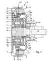
- Figure 1 shows a planetary gear 50 with the switching mechanism according to the invention.
- a wave 2 z. B. a crankshaft of an internal combustion engine
- the front side is a chain, or toothed belt wheel 2a for driving the camshaft by means of a shaft screw 2b attached.
- the attachment takes place for example by means of a frictional connection between the wheel 2a and the end face of the shaft 2, by tightening the shaft screw 2b.
- a wedge 2c serves for the angular orientation of wheel 2a and shaft 2.
- wheel 2a circlip 1 b be used.
- On the wheel 2a is also by means of screws 1c fixed a damper 1, which is fixedly connected to the shaft 2 and with rotation of the shaft 2 with this is revolving.
- On the shaft screw 2b are also essential parts of the planetary gear 50 rotatably mounted or are fixedly formed on this.
- a web 3 of the planetary gear is fixed trained with this.
- the web 3 comprises axes 16 on which planet gears 16a are rotatable are stored.
- the teeth of the planet gears 16a engage in an inner sprocket 19 of a Ring gear 20 a.
- Via a connecting web 21 is a link 8, a first essential Part of the switching device according to the invention forms, fixedly connected to the ring gear 20, between the connecting web 21 and the web 3 on the front side of the axes 16 for adjusting the axial play of the planet gears 16a and to reduce the friction a thrust bearing 17 is attached.
- the thrust bearing 17 is preferably a friction ring, the z. B. may consist of plastic.
- a sun gear 5 of the planetary gear 50 rotatably supported on this.
- the storage takes place z. B. by means Needle roller bearings, preferably needle sleeves 15, wherein also a different storage can be selected can.
- the pulley 4 z is at the outside end face. B. by means firmly connected to a weld.
- the shaft 2 with the Starter generator (not shown) connected via a belt, with other units such as B. an air conditioner can be driven.
- the shaft screw 2b is the front side with a z. B. attached to the pulley 4 cover 4 b covered.
- a hollow shaft 9 e Between the web 3 and a Tilger 1 is a hollow shaft 9 e, the second forms a substantial part of the switching device according to the invention.
- This is also rotatable mounted on the shaft screw 2b, wherein it comprises a pin connection 9a to a fixed To hold connection with a pin 9 engaging in a groove of the crank plate 9.
- the Hollow shaft 9e is axially movable only in the context of a minimal bearing clearance, which also by means of a thrust bearing 25 is adjustable.
- the thrust bearing 25 can also as Friction disc be formed.
- the hollow shaft 9e comprises an external thread 10, on a nut 10a is rotatably arranged.
- the nut 10a is via a Hohlradtagen 23 connected to the ring gear 20 so that the nut 10 a relative to the ring gear 20th axially displaceable by rotation on the hollow shaft 9e, wherein between nut 10a and Ring gear 20 always a rotational connection should exist.
- This can be z. B. achieved thereby be that a toothing in the outer region of the ring gear 23 in the sprocket 19 of the ring gear engages, and a corresponding axial toothing in the interior of the Hohlradtagen 23 in a complementary to this toothing on the nut outside intervenes.
- the transmission 50 is rotatably mounted on the nut 10a, a coupling ring 10b attached.
- this is axially by a on the mother 10a molded projection and by a projection opposite to the mother 10a applied circlip 10c fixed.
- This z. B. by means of a Friction disc 10e or other bearing element for axial bearing and bearing clearance adjustment this set
- the coupling ring 10b can be relative to the mother 10a turn to this, but he in the axial direction, due to the axial fixation with the mother, being moved with this.
- Form radial parts 10d of the coupling ring 10b Pressure plates of a first part of a clutch 7, which here designed as a multi-plate clutch is.
- the pin connection 9a leads, at the axial direction, a penetration element 9c is welded, by means of the passage element 9c through one on the coupling ring 10b radially arranged opening.
- a penetration element 9c is welded, by means of the passage element 9c through one on the coupling ring 10b radially arranged opening.
- the hollow shaft 9e is rotationally locked connected to the coupling ring 10b, that is, a relative rotation the hollow shaft 9e to the coupling ring 10b is prevented.
- a penetration element 9c is by means of elastic elements, such as. B.
- the clutch 7 therefore comprises two coupling units K1 and K2, wherein the coupling unit K1 z. B. is closed by friction, by the stationary housing 6 facing radial parts 10d of the coupling ring 10b are brought to the housing 6 to the plant.
- the coupling unit K2 is closed by the fact that the coupling ring 10b with its radial parts 10d to the pressure plates located on the absorber 1 1a and 1b for Plant is brought.
- Sealing elements 14, 24 and 24a seal the running in oil or fat planetary gear set.
- the gate circuit consisting of link plate 8, pin 9, Leaf springs 9b, pin connection 9a, hollow shaft 9b, nut 10a, thread 10, coupling ring 10b and passage member 9c is arranged between the drive and output so that they also ensures the corresponding frictional connection, that is over parts (essentially over Guide disc 8, pin 9, passage member 9c and parts of the coupling ring 10b) of Sliding the torques are transmitted from the shaft 2 to the pulley 4 or the other way around.
- the coupling units are arranged so that only one Clutch can be closed, the other is then open.
- the relative angular rotation between pin and link plate is by stop points in the link plate limited, so that a rotation of about 340 ° is possible. This is the maximum at the same time Twisting of the thread 10 and thus the movement of the radial parts 10d of the coupling ring, which act as pressure plates and attached to the outer circumference of the coupling ring 10b are.
- the thread 10 is advantageous in the embodiment shown in FIG arranged far inside, to the lowest possible frictional torque of the thread at high axial force to be able to produce.
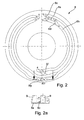
- the link disc 8 comprises a preferably self-contained groove 8a.
- groove sections as shown in the exemplary embodiment, can be arranged almost concentrically with one another in sections.
- the pin 9 is guided at a rotation of the groove and pin. Transmits z. B. the engine via the transmission power to the pulley 4, the pin 9 is at the point 1 of the backdrop, and the torque is transmitted to this stop point.
- the scenery 8 rotates clockwise and takes the pin, so to speak. For the transmission shown in Figure 1, this results in a ratio of 1: 1, so it is transmitted power from the crankshaft to the starter generator, which operates as a generator.
- the starter generator is thus driven, which is why such a state is also referred to as "train 1: 1".
- the groove shape in Figure 2 allows in position 2 on the gate 8 a booster operation, that is, it will be transmitted power and torque from the starter generator to the backdrop.
- the starter generator is driven as a motor with a slightly higher speed than it would have due to the "train 1: 1” operation.
- the pin moves away from the stop point, which is also referred to as point 1, and is rotated by the slot in an attachment point 2, twisted in the direction of the cam slip, via which it transfers torque to the internal combustion engine or the shaft 2. This condition is referred to as "thrust 1: 1" because the starter generator applies a positive torque M + .
- the anchor point 2 is only so far away from the anchor point 1, that maintained by this rotation of backdrop and pin, the coupling units essentially their positions.
- By speed reduction on the starter generator or by acceleration of the engine relative to the starter generator pin 9 is again rotated in the other direction and comes - guided by the groove (and a return 8c, see below) - in the gate position 3.
- the state again "Train 1: 1" given because position 3 is the same angle to the gate position 1, and thus no adjustment of the coupling device takes place.
- each stop point is an axial Return 8c arranged, which is shown schematically in Figure 2a.
- the return 8c is formed wedge-shaped and engages in the groove 8a, so that a pin 9, the groove 8a only in one direction, otherwise at a steep end, which is preferred is formed perpendicular to the groove 8a, comes to rest.
- the wedge 8c a Form stop point for the pin, if this arranged in the groove approximately in the direction of rotation is.
- the return 8c is z. B. by means of a plate 8e on the opposite Side of the Pineingriffs attached. In this case, the return resiliently on the plate 8e or be held on the link plate 8 or be firmly connected to this.
- In the second Trap becomes the pin displacement (perpendicular to the groove) due to the rebound by a spring held pin 9 balanced, z. B. by means of leaf springs 9b, as shown in Figure 1 is.
- the recesses 8c are essentially used to guide the pin 9. So z. B. ensures that the pin is continued defined after leaving an anchor point, wherein with closed slide tracks the same anchorage point again after a run the groove 8a is reached. In FIG. 2, the recesses 8c are identified by lines 8d.
- a gear change can not only by accelerating the starter generator but be enforced by strong deceleration of the shaft 2, since also here a corresponding Twist of pin 9 and backdrop 8 result.
- This is z.
- a strong braking with a gear engaged eg in an ABS braking
- a gear upshift e.g in a gear upshift.
- This would result in the PTO to undesirably high braking accelerations and to a possible overload of the components.
- the state of the opened clutches maintained until the braking process is completed.
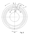
- FIG. 3 An example of an embodiment of a backdrop with centrifugal lock is shown in Figure 3.
- a centrifugal lock 13 engages in a region of the groove 8 a at high speed and locked the pin 9 a rotation in the direction of the switching position 5 of the high gear ratio.
- the centrifugal lock is rotatable at one end by means of a bearing 13b on the link plate 8 fixed and biased radially inwardly with a spring 13 a, so that they at small speeds does not come into effect. Only at higher speeds, when the centrifugal force is sufficiently high, the centrifugal lock rotates in the groove 8a. As a result, z. B. a Switching from the low to the high gear ratio at high speeds prevented become.
- an axial recess 8g attached.
- This can be with the internal combustion engine (Shaft 2) in this position, when both clutches are opened, through the Starter generator z. B. an auxiliary pulley located on the pulley, z. B. a Klmastrom, operated (switch position 7).
- the couplings can be designed without torque overlap.
- a friction device can, for. B. a spring plate 11 (see FIG 1) serve.
- the Spring plate 11 z. B. radially shifted slightly by the pin something in the radial Moves direction, then to a kind of ratchet structure 12 on the housing to the plant come. The radial displacement of the pin is achieved via the groove 8 a in that this approaching the backdrop.
- the Rateschenfashioned is designed so that when driving the Auxiliary units with open coupling units K1 and K2 in the direction of positive direction of rotation of the generator (drive direction of the ancillaries) only a small drag torque is generated, whereby the starter generator loaded by the planetary gear little becomes. In the other direction, however, the drag torque is higher, the friction in the To overcome thread 10 better, whereby a shift is only possible.
- a particular advantage of the embodiment shown in Figure 1 is that only the planetary gear running in oil lubrication, but not the other components, especially not the Clutch and the gate circuit.
- the Clutches also work with the high dry friction coefficient, thereby reducing the required Contact forces are smaller.
- the drag losses are lower than those in clutches occur in an oil bath.
- the radial shaft seals 24 and 14 for Seal of the planetary gearset be mounted far in, resulting in lower Drag torques in the planetary gear set and thus a better efficiency.
- FIG. 4 shows a simplified linear representation of the planetary gear according to the invention from Figure 1.
- the clutches K1 and K2 are shown, which by means of Thread 10 are shifted when switching the transmission.
- the torque is from the shaft 2 first transferred to the web 3.
- a part of the torque by means the planet gears 16a transferred to the ring gear 20 and a part of the sun gear 5, according to the associated transmission ratios.
- the link plate 8 At the ring gear 20 is the link plate 8, in which the pin 9 engages.
- the backdrop 8 corresponds approximately to that shown in FIG. If the pin 9, for example, from shift position 1 of the gate 8 to switch position 5 moves, so K1 closes and K2 opens.
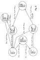
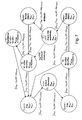
- FIG. 5 shows a state diagram which shows the various switching states of the planetary gear mechanism from FIG. 1 with the link disk from FIG.
- the numbers in the circles indicate the corresponding switching states of the scenery.
- M KW and M RS are the respective torques on the crankshaft 2 and the pulley 4, where "+” means an increase and “-” means a decrease of the torque.
- M Tow denotes the drag torque of the clutch, which can be positive “+” or negative “-” and is a function of the speed (f (delta n)).
- the adjustment angle between pin 9 and crank plate 8 is generally denoted by Dj and results from the time-integrated speed difference of crankshaft 2 and pulley 4 (nKW and nRS) when the gear ratio is 1: 1, otherwise the gear ratio (iPlanet) must be considered ,
- the Dj indicated in FIG. 5 are the required angular rotations in order to achieve the corresponding switching states on the link disk 8.
- the state diagram clarifies that the states can only be traversed in one direction due to the axial recesses, whereby two possible paths result in the switching state 4. If the starter generator is slower than the shaft 2, the groove area 8b (FIG. 2) leads to the switching position 1 on the link disk.
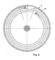
- Figure 6 shows another link plate for a transmission according to the invention.
- a centrifugal force lock 13 is mounted in the groove portion 8b is, which switches from the low gear ratio to the high gear ratio of the transmission.
- the Centrifugal lock 13 blocks the groove 8b at high speeds, so that an upshift of Translation is not possible.
- a special feature of this scenery disc is that they are part of the Front side of the pulley 4 is, wherein the groove 8a incorporated in the pulley end face are.
- the gate includes an additional recess 8h in the groove 8a, thereby it is possible to switch a generator high mode (switching position 5 '), that is the starter generator and the ancillaries are with 3: 1 or with the gear ratio driven (“thrust 3: 1").
- the groove portions 8i and 8k serve the outer To achieve switching positions 1 and 5 faster, without having to drive through the entire groove. This can z. B. from “train 1: 1” in the shaft position 3 to "thrust 1: 1" in the shaft position. 2 be switched faster without opening the coupling units. Likewise of “thrust 3: 1" in the outer switching position 5 without opening the coupling units in the "Train 3: 1" to be switched. "
- FIG. 7 shows the state diagram associated with FIG. 6 analogously to FIG. 5.
- a new switching state 5 ' in which the starter generator is operated in high operation. Due to the switching state 5 'results in a further shaft state 5 (outside), where a "thrust 3: 1" is possible, that is, where the starter generator the shaft 2 drives.
- a centrifugal lock can be used be engaged at shaft speeds less than 500 U / min in the groove and the pin to her to Plant comes, whereby a "thrust 3: 1" operation is switched. Exceeds the shaft speed a critical speed, so the centrifugal force protection opens the groove and there is a switch the translation of z. B. 3: 1 to 1: 1, whereby the ancillaries protected against overspeeding become.
- Figure 8 is analogous to Figure 6 link disc 8 with the same switching states, however shown without centrifugal lock, but also attachable.
- the difference to The backdrop of Figure 6 is that a rotation of about 700 ° between pin 9 and link plate 8 is necessary to switch between the coupling units K1 and K2.
- this solution is disadvantageous with a higher Friction wear connected to pin 9 and groove 8a.
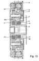
- Figure 9 shows a further embodiment of the transmission according to the invention, in the ring gear 20 is permanently connected to the stationary housing 6.
- the Shaft 2 crankshaft
- the bridge 3 is connected to the sun 5, and in the lower translation (1: 1), the pulley 4 is connected directly to the web 3.
- the advantages are characterized by the far inner coupling units and given the internal thread, resulting in small friction moments to let.
- the disadvantage is that at the small translation (1: 1) the planets empty revolve, causing friction losses.
- the pin 9 is held via a spring-trained pin connection 9a, which on a Passage element 9c is mounted, which (eg star-shaped) by a Coupling ring 10b attacks, the pressure plate for opening and closing the coupling units K1 and K2 carries.
- the penetration element 9c is with respect to axial displacement by means of a securing ring 22 or a corresponding thrust bearing secured against axial displacement, as well as a screw sleeve 15, which is located on a located in the center of the transmission screw 14a.
- the Screw 14a is axially movable and includes a thread 10 and a thread 10 ' with reverse slope.
- FIG. 10 shows a further exemplary embodiment of a planetary gear according to the invention with a structure similar to that shown in FIG.
- the thread is 10th arranged outside and the pin 9 and the crank disc 8 are in the radial direction between the coupling units K1, K2 and the ring gear 20, the link 8 on the ring gear 20 and the pin 9 is attached to the coupling carrier.
- a special spring band thread 30 (“Raberfeder") is used, which is a special development representing the applicant and is described in more detail in DE 100 81 936.
- spring band thread 30 is a resilient flat steel (spring band) helically wound, wherein its flat side is arranged in the radial direction.
- spring steel z When used as a thread is the spring steel z.
- Figure 11 shows schematically a similar embodiment according to the invention as in Figure 10, wherein the couplings K1, K2 and the spring band thread 30, as well as slide 8 and pin 9, 9 '(9 and 9 'are connected to a leaf spring 9b, not shown) arranged in a different position are.
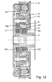
- FIG. 12 shows a further embodiment of the planetary gear according to the invention, wherein the pulley 4 with the ring gear 20 and the crankshaft 2 with the web 3 is connected.
- the sun gear 5 is optionally connected to the stationary housing 6 (high Translation, z. B. 3: 1) or the web (small translation, eg 1: 1) connected. Furthermore, will the sun gear 5 is centered by three stepped planet wheels 16a and has a thread inside 10 trained.
- the link plate 8 is supported on the housing 6 or on the web 3 via the Hollow shaft 9e, which includes an external thread, which with the thread 10 of the sun gear 5 is in operative connection.
- the pin 9 is connected to the sun gear 5. Will the pin 9 relative shifted to the backdrop 8, so the hollow shaft is rotated 9e and is displaced axially. As a result of this axial movement, the clutches K1 and K2 become corresponding to the preceding ones Embodiments shifted.
- adjusting thread 10 and the couplings K1, K2 are arranged inside the planetary gear set, with small friction moments at the adjusting thread and outside space for the arrangement of absorber and Vibration damper is.
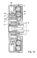
- Figure 14 shows an embodiment of a planetary gear, in which the multi-plate clutches are replaced by jaw clutches 41, 42, wherein the creation of the couplings means an actuator 40 takes place, which replaces the gate circuit.
- Jaw clutches 41, 42 requires that with the starter generator always the Synchronous speed of each gear can be approached to the Claw clutches 41, 42 to switch into the respective recesses 42.
- the advantage is that switches in any switching state as often and thus a change of train and Thrust can be achieved. It is also advantageous that at engine standstill (standing wave 2) almost no drag torque occur, causing ancillaries such. B. occur, whereby ancillaries such. As air conditioners, operated with good efficiency can be.
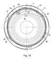
- FIG. 16 and 17 a transmission is shown, in which a link plate 8 of FIG. 15 is an overall front view of a section of FIG. 16.
- FIG is that shows a modified planetary gear according to the invention.
- FIG. 17 shows in one enlarged detail of the individual functional elements of the modified transmission.
- the link disc 8 is shown in a switching position for a ratio of 1: 1.
- the slide track 8a has at the switching points 1,3 and 5, 5 'a radially extending Groove section on. If the pin has arrived in this groove section, he can not initially leave. He is form-fitting with very little play by a flyweight 67, with which the Pin is connected, held in the groove.
- the game is designed much smaller, causing the pin within the Nutbegrenzonne during a pull / push change (a reversal of the currently applied torque) only little is moved. This results in a lower noise. Furthermore, vibrations occurring in the drive can not cause unwanted gear changes. Furthermore, in a shaft position without intervention of the starter generator as often as desired be changed between train / thrust.
- a changeover of the gear ratio always takes place when it is exceeded or falling below a limit speed at which the pin 9 from the inside out or vice versa migrates along the radially formed groove portion.
- the disturbances of the switching process frictional forces caused by moments transmitted at the pin reduced by the constantly existing vibrations, since these a change of plant of Pins cause, whereby always prevail for a short time low frictional forces.
- To this Time pin 9 can then with increasing centrifugal force to the outside or at decreasing Centrifugal force to move inwards.
- the pin switched by the starter generator from the ratio 1: 1 to a higher one (eg 3: 1), since he is now on the inner groove section.
- the switching process z.
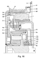
- Figure 16 shows an analog planetary gear to that in Figure 1, but with modified Sliding link and additional connection and control elements on the housing and on the pulley. The same parts are the same.
- the ring gear 20 is separated from the housing when the shaft screw 2b is stationary, so that this is free to spin.
- the release and connection of the Ring gear 20 with the housing by means of a support ring 66 and pins 64 which are in recesses 69 can engage in the support ring 66.
- the pins 64 are radial for this purpose movably attached to a ring 65 made of spring steel, this being for improvement have the radial mobility of the pins 64 in the vicinity of recesses can, so that a spring-like mounting of the pins is achieved.
- the ring 65 simultaneously serves to support the torque and is connected to the housing 6.
- a rotation of the Ramprings 63 connects by 30 ° and solves a connection between the spring plate ring 65 and carrier ring 66.
- the Rampring is at least partially resilient, because the pins 64 and the recesses 69 on the carrier ring 66 are not always synchronous stand, whereby the pin biased if necessary, and then by means of the starter generator the correct angular position can be approached. To control an actuator to save the Ramping 63, this is targeted twisted by the generator.
- a freewheel plate 62 which on the pulley 4 is fixed by means of a ring 61, and rotated with this. Femer becomes the fact exploited that the pulley 4 in operation relative to the housing always only right (operating direction) moves, bringing a turn in the other direction can be used for switching.
- the freewheel plate 62 includes spring-trained wedge-shaped elements, depending on the direction of rotation of the pulley 4 with different Angles on Rampring 63 come to the plant. This will create a "ratchet mechanism" achieved, by means of which the Rampring 63 are passed over or twisted can.
- the ram ring 63 is skipped and maintains its position relative to the spring washer. Turns the pulley 4 in the other direction, the ram ring is taken and the pins 64 can with the recesses 69 of the support plate are connected, creating a connection between ring gear 20 and housing 6 is made. At higher speeds in the operating direction the friction between freewheel plate and ram-ring is thereby reduced that the wedge-shaped elements of the freewheel plate 62 by the centrifugal force to the outside Move away from Rampring 63. This increases the efficiency in normal operation.
- Pos. designation Pos. designation Pos. designation Pos. designation 1 absorber 21 connecting web 101 1b circlip 22 circlip 102 1c screw 23 Hohlradtagen 103 1d pressure plate 24 sealing element 104 2 Shaft, crankshaft 24a sealing element 105 2a Chain, timing belt, wheel 25 thrust 106 2 B shaft screw 30 Spring band thread 107 2c wedge 40 actuator 108 3 web 41 claw clutch 109 4 pulley 42 claw clutch 110 4b cover 43 recesses 111 5 sun 50 planetary gear 112 6 casing 61 ring 113 7 clutch 62 Freewheel sheet 114 8th Scenery, backdrop 63 Rampring 115 8a groove 64 pen 116 8b Groove, groove area 65 Spring steel ring 117 8c return 66 support plate 118 8d Return, line 67 flyweight 119 8e plate 68 Return spring 120 8f Return in the groove 69 recess 121 8g axial return 72 122 8i groove sections 73 123 8k groove sections 74 124 9 Pin code 75 125 9 ' Pin code
Landscapes
- Engineering & Computer Science (AREA)
- General Engineering & Computer Science (AREA)
- Mechanical Engineering (AREA)
- Chemical & Material Sciences (AREA)
- Combustion & Propulsion (AREA)
- Transmission Devices (AREA)
- Structure Of Transmissions (AREA)
Abstract
Description
Die vorliegende Erfindung betrifft ein Planetengetriebe mit den Komponenten Gehäuse, Sonnenrad, Hohlrad, Steg mit Planetenrädern, zwei bezüglich Öffnen und Schließen entgegengesetzt wirkenden Kupplungseinheiten K1 und K2 einer Kupplung, sowie einem Kupplungsbetätigungselement, wobei eine erste Komponente einen ersten Getriebeanschluss bildet und mit der Antriebswelle eines ersten Antriebsaggregats, vorzugsweise eines Verbrennungsmotors, verbindbar ist, und eine zweite Komponente einen zweiten Getriebeanschluss bildet, der vorzugsweise eine Riemenscheibe umfasst, wobei die erste und zweite Komponente durch die Kupplungseinheiten K1 oder K2 kraftschlüssig miteinander verbindbar sind.The present invention relates to a planetary gear with the components housing, sun gear, Ring gear, bridge with planet gears, two opposite opening and closing acting coupling units K1 and K2 a clutch, and a clutch actuator, wherein a first component forms a first transmission connection and with the drive shaft of a first drive unit, preferably an internal combustion engine, is connectable, and a second component forms a second transmission connection, preferably a pulley, wherein the first and second components through the Coupling units K1 or K2 frictionally connected to each other.
Ferner betrifft die Erfindung ein Verfahren zum gezielten Schalten eines zwei Übersetzungsstufen umfassenden Planetengetriebes mit zwei Getriebeanschlüssen.Furthermore, the invention relates to a method for targeted switching of a two gear ratios comprehensive planetary gearbox with two gearbox connections.
Planetengetriebe werden z. B. an Kurbelwellen von Verbrennungsmotoren eingesetzt, wobei Startergeneratoren im Nebenabtrieb betrieben werden, wie dies z. B. für Startergeneratoren und Verbrennungsmotoren umfassende Antriebseinheiten in der auf die Anmelderin zurückgehenden deutschen Patentanmeldung DE 199 41 705 A1 beschrieben ist. Dabei werden die Getriebeübersetzungsstufen selbsttätig als Funktion des Betriebsmodus des Getriebes bzw. der Antriebseinheit eingestellt, sodass z. B. während des Startvorgangs der Startergenerator mit einer Getriebeübersetzung untersetzt wird. Bei laufendem Verbrennungsmotor oder im Boosterbetrieb des Startergenerators hingegen erfolgt eine Reduktion der Getriebeübersetzung, um zu hohe Drehzahlen des als Generator wirkenden Startergenerators zu vermeiden, oder, um beim Boosterbetrieb, bei dem der Startergenerator als Elektromotor den Verbrennungsmotor unterstützt, eine höhere Kurbelwellendrehzahl als die Startdrehzahl zu ermöglichen.Planetary gear z. B. used on crankshafts of internal combustion engines, wherein Starter generators are operated in the power take-off, as z. B. for starter generators and internal combustion engines comprehensive drive units in the applicant German Patent Application DE 199 41 705 A1 is described. Here are the Gear ratio stages automatically as a function of the operating mode of the transmission or set the drive unit, so z. B. during startup of the starter generator is reduced with a gear ratio. When the combustion engine is running or in Boosterbetrieb the starter generator, however, there is a reduction of the gear ratio, to avoid too high rotational speeds of the starter generator acting as a generator, or, in the booster mode, where the starter generator as an electric motor, the internal combustion engine helps to allow a higher crankshaft speed than the starting speed.
Ferner sind Antriebseinheiten mit Planetengetrieben bekannt, bei denen die Getriebeübersetzung
von außen geschattet wird. Ein Beispiel für eine geschaltete Kupplung ist in DE-PS 41
12 215 angegeben.Furthermore, drive units with planetary gears are known in which the gear ratio
Shadowed from the outside. An example of a switched clutch is in DE-PS
Bei den bekannten Planetengetrieben ist entweder ein Aktor zur Schaltung der Getriebeübersetzung notwendig, wodurch zusätzliche Kosten entstehen und sich auch die Störanfälligkeit und das Gewicht der Antriebseinheit erhöhen, oder, bei selbsttätig geschalteten Getrieben, ist ein gezieltes Schalten des Getriebes nicht möglich, wodurch z. B. beim Boosterbetrieb eine den Erfordernissen optimal angepasste gezielte Gangwahl nicht möglich ist.In the known planetary gears is either an actuator for switching the gear ratio necessary, resulting in additional costs and also the susceptibility and increase the weight of the drive unit, or, in automatically connected transmissions, is targeted switching of the transmission is not possible, whereby z. B. in booster mode one the requirements optimally adapted targeted gear selection is not possible.
Es ist die Aufgabe der vorliegenden Erfindung, diese Nachteile zu beseitigen und ein Planetengetriebe zu schaffen, welches in der Antriebseinheit keine zusätzlichen Aktoren zum Übersetzungswechsel benötigt und bei welchem während des Betriebs ein Übersetzungswechsel möglich ist.It is the object of the present invention to eliminate these disadvantages and a planetary gear to create, which in the drive unit no additional actuators for ratio change needed and at which during operation a gear change is possible.
Die vorliegende Aufgabe wird durch ein Planetengetriebe der eingangs genannten Art dadurch gelöst, dass das Kupplungsbetätigungselement eine Kulissenscheibe mit Nut und einen in der Nut der Kulissenscheibe geführten Pin umfasst, wobei Kulissenscheibe und Pin relativ zueinander um einen begrenzten Winkel verdrehbar sind.The present object is characterized by a planetary gear of the type mentioned by solved that the clutch actuator a link disc with groove and a in the groove of the link plate guided pin, where link plate and pin relative can be rotated by a limited angle to each other.
Ferner wird die vorliegende Aufgabe durch ein Verfahren gelöst, bei dem ein gezieltes Schalten eines zwei Übersetzungsstufen umfassenden Planetengetriebes, mit zwei Getriebeanschlüssen, einer eine Nut umfassende Kulissenscheibe mit einem in der Nut geführten Pin zur Getriebesteuerung und zur Übertragung des Getriebedrehmoments, dadurch erfolgt, dass das Schalten mittels einer am zweiten Getriebeanschluss angreifenden drehzahlsteuerbaren Antriebseinheit durch gezieltes Beschleunigen oder Verzögern ihrer Drehzahl relativ zur Drehzahl des zweiten Getriebeanschlusses erfolgt, indem sich der in der Nut der Kulissenscheibe geführte Pin relativ zu dieser um einen Winkel verdreht, und abhängig von der Größe der Winkeldrehung zwei bezüglich Öffnen und Schließen entgegengesetzt wirkende Kupplungseinheiten K1 und K2 einer Kupplung betätigt, die ein Umschalten von einer Übersetzungsstufe zur anderen ermöglichen.Furthermore, the present object is achieved by a method in which a targeted switching a two-speed planetary gearbox, with two gearbox connections, a slot comprising a groove with a guided in the groove pin to Transmission control and transmission of the transmission torque, characterized in that the Switching by means of a speed-controllable drive unit acting on the second gearbox connection by selectively accelerating or decelerating their speed relative to the speed of the second gear connection is made by the in the groove of the link plate guided pin relative to this twisted by an angle, and depending on the size of the Angle rotation two with respect to opening and closing opposite acting coupling units K1 and K2 a clutch operated, the switching from a translation stage to enable others.
Durch das erfindungsgemäße Getriebe kann vorteilhaft mittels des erfindungsgemäßen Verfahrens eine gezielte Einstellung der möglichen Übersetzungsstufen während des Betriebs in einer Antriebseinheit erfolgen. Ferner ergeben sich durch die Anwendung einer Kulissenscheibe als Teil eines Kupplungsbetätigungselements weitere Vorteile, die nachfolgend anhand bevorzugter Ausführungsbeispiele dargestellt sind.By the transmission according to the invention can advantageously by means of the method according to the invention a targeted adjustment of the possible gear ratios during operation in a drive unit. Furthermore, result from the application of a link plate as part of a clutch actuator further advantages, the following reference preferred embodiments are shown.
Die Kulissenscheibe wird bevorzugt mit einer radial oder axial verlaufenden Nut versehen, wobei, bezogen auf die Kulissenscheibe, bei axialem Verlauf der Pin in einer axialen Richtung in die Nut eingreift, bzw. bei radialem Verlauf der Pin in radialer Richtung in die Nut eingreift. Damit ergibt sich vorteilhaft die Möglichkeit, das Eingreifen des Pins der Konstruktion des Planetengetriebes so anzupassen, dass dabei kompakte Bauformen beibehalten werden können. The link plate is preferably provided with a radially or axially extending groove, wherein, relative to the link plate, the axial direction of the pin in an axial direction engages in the groove, or engages in the radial direction of the pin in the radial direction in the groove. This advantageously results in the possibility of engaging the pin of the construction of the planetary gear adapt so that compact designs can be maintained.
Dabei kann, je nach Anordnung der Kulissenscheibe innerhalb des Getriebes, z. B. am Hohlrad, dem Sonnenrad oder dem Steg, aus Raumgründen die eine oder die andere Form bevorzugt werden.It can, depending on the arrangement of the crank disc within the transmission, z. B. on the ring gear, the sun gear or the bridge, for reasons of space preferred one or the other form become.
Vorzugsweise weist die Nut links- und rechtsseitige Anschlagpunkte auf, um den Drehwinkel zwischen Pin und Kulissenscheibe bei links- und rechtsseitiger Relativdrehung an diesen zu begrenzen. Diese definierte Relativdrehung kann dabei vorteilhaft zur Schaltung des Getriebeübersetzungsverhäftnisses von einer Stufe in eine andere verwendet werden. Da der Pin innerhalb der Nut an zwei definierten Stellen einmal links und einmal rechts an der Kulissenscheibe anliegt, lassen sich links- und rechtsdrehende Momente mittels der Kombination Pin-Kulissenscheibe übertragen.Preferably, the groove has left and right side stop points to the rotation angle between pin and link plate at left and right side relative rotation to this limit. This defined relative rotation can be advantageous for the circuit of Getriebeübersetzungsverhäftnisses be used from one level to another. Because the pin within the groove at two defined points once to the left and once to the right on the link plate is applied, can be left and right-handed moments by means of the combination Pin-link disc transfer.
In einer weiteren vorzugsweisen Ausführungsform weist die Kulisse vor wenigstens einem Anschlagpunkt der Nut einen etwa keilförmigen Rücksprung innerhalb der Nut auf, wobei die erhöhte Seite des Rücksprungs zum Pin hin und in Richtung des Anschlagpunkts weist. Damit wird sichergestellt, dass ein durch den Pin über eine erste Bahn der Nut einmal erreichter Anschlagpunkt nicht wieder auf der gleichen Bahn verlassen werden kann. Der Pin kann also den Anschlagpunkt nur auf einer anderen Bahn der Nut verlassen. Damit lassen sich vorteilhaft Nuten innerhalb einer Schaltkulisse erzeugen, die mittels des Pins z. B. nur in eine Richtung durchlaufen werden können. Mit einem Rücksprung oder mehreren Rücksprüngen kann somit alleine mittels relativer Verdrehungen von Pin und Kulissenscheibe eine bestimmte Schaltsequenz des Getriebes erreicht werden, ähnlich wie mit einer Logikschaltung. Ferner kann der Rücksprung so ausgebildet sein, dass er zwischen Kulissenscheibe und Pin ein Drehmoment übertragen kann, z. B., wenn der Pin am hohen Ende des Rücksprungs in einem Nutabschnitt anliegt, der von der reinen Radialrichtung abweicht. Ferner kann die Nut selbst einen Rücksprung aufweisen, indem sie an einem Anlagepunkt einen spitzen Winkel keiner als 90° bildet.In a further preferred embodiment, the backdrop before at least one Anchor of the groove on an approximately wedge-shaped recess within the groove, wherein the elevated side of the return points to the pin and in the direction of the stop point. In order to it is ensured that a stop point once reached by the pin via a first track of the groove can not be left on the same track again. So the pin can leave the anchor point only on another track of the groove. This can be advantageous Create grooves within a shift gate, which means z. B. only in one direction can be passed through. With one return or multiple returns can thus alone by means of relative rotations of pin and link plate a specific Switching sequence of the transmission can be achieved, similar to a logic circuit. Further the return can be designed so that it is between the link plate and pin Can transmit torque, z. B. when the pin at the high end of the return in one Groove portion is applied, which deviates from the pure radial direction. Furthermore, the groove itself have a return by not making an acute angle at an investment point as 90 ° forms.
Bei der Verwendung von Rücksprüngen weist die Nut vorteilhaft eine in sich geschlossene Struktur auf, sodass der Pin einen Punkt innerhalb der Nut nach Durchlaufen der gesamten Nut, oder eines Teils der Nut, wieder zum selben Punkt gelangt. Dadurch kann jeder Punkt und damit auch jeder Anschlagpunkt innerhalb der Nut beliebig oft erreicht werden, wodurch die mit einer Nutposition verbundenen Schaft- oder Steuerfunktionen beliebig oft ausführbar sind. When using recesses, the groove advantageously has a self-contained Structure up so that the pin makes a point inside the groove after passing through the entire Groove, or part of the groove, comes back to the same point. This can be any point and thus every stop point within the groove can be reached as often as desired, whereby the connected with a groove position shank or control functions as often executable are.
In einer weiteren vorzugsweisen Ausführungsform weist die Kulissenscheibe mehrere etwa zum Kulissenmittelpunkt konzentrisch oder axial nebeneinander liegende Nutabschnitte auf, welche untereinander wenigstens einmal miteinander durch eine Nut verbunden sind. Damit ergeben sich insbesondere bei geschlossenen Nuten eine Vielzahl von Steuermöglichkeiten; insbesondere kann erreicht werden, dass die relative Verdrehung von Kulissenscheibe und Pin größer als eine Umdrehung sein muss, um von einem Schaltzustand, z. B. von einem Anschlagpunkt, zu einem zweiten zu kommen. Ferner können die links- und rechtseitigen Anschlagpunkte symmetrisch angeordnet sein.In a further preferred embodiment, the link plate several about to the middle of the gate concentric or axially adjacent groove sections, which are interconnected at least once with each other by a groove. In order to arise in particular with closed grooves a variety of control options; In particular, it can be achieved that the relative rotation of link plate and Pin must be greater than one revolution to switch from a switching state, eg. B. from an anchor point, to come to a second. Furthermore, the left and right attachment points be arranged symmetrically.
Vorzugsweise werden die Nuten kreisabschnittsförmig auf einer vorzugsweise runden Kulissenscheibe angeordnet, wobei sich ihr Radius auf einer vorgegebenen Winkeldistanz ändert. Damit eröffnet sich vorteilhaft die Möglichkeit, dass der in der Nut geführte Pin beim Durchlaufen der Nut Steuerfunktionen ausführen kann, die nicht nur von seiner Winkelposition, sondern auch von seiner Radialposition auf der Kulissenscheibe abhängen, wodurch die Steuermöglichkeiten erweitert werden.Preferably, the grooves are circular section on a preferably round link plate arranged, with their radius changes at a predetermined angular distance. This advantageously opens up the possibility that the guided in the groove pin when passing through The groove can perform control functions that not only depend on its angular position also depend on its radial position on the link plate, creating the control options be extended.
In einer weiteren vorzugsweisen Ausführungsform der Erfindung ist an wenigstens einer Stelle der Nut auf der Kulissenscheibe eine Fliehkraftsperre angebracht, die in die Nut eingreift, wenn eine bestimmte Drehzahl der Kulissenscheibe über- oder unterschritten wird. Damit wird der Pin durch die Fliehkraftsperre in seiner Bewegung innerhalb der Nut eingeschränkt. Vorzugsweise wird die Fliehkraftsperre in der Nähe eines Anschlagspunkts angeordnet, um bei einer bestimmten Drehzahl oder einem Drehzahlbereich den Pin zwischen Anschlagpunkt und Fliehkraftsperre zu halten. Damit kann der in der Kulissenscheibe geführt Pin neben winkel- und radiusabhängige auch drehzahlabhängige Steuerfunktionen übernehmen.In a further preferred embodiment of the invention is at least one point attached to the groove on the link plate a centrifugal lock, which engages in the groove, when a certain speed of the link plate is exceeded or fallen below. This will be the pin is restricted by the centrifugal lock in its movement within the groove. Preferably the centrifugal lock is placed near a stop point to at a certain speed or a speed range the pin between anchor point and To hold centrifugal lock. This allows the pin guided in the link disc to be angularly and take over radius-dependent and speed-dependent control functions.
Vorteilhaft können die Nuten in einer Stirnseite einer Riemenscheibe angebracht sind, die z. B. um das Planetengetriebe angeordnet ist, wobei dann diese Stirnseite auch als Kulissenscheibe dient, in die ein Pin zu Steuerungszwecken eingreift. Damit lässt sich die Kulissenscheibe als eigenständiges Bauteil einsparen. Ferner kann eine eigenständige Kulissenscheibe auch mit dem Hohlrad oder mit einer anderen rotierbaren Komponente (Steg, Sonnenrad, Riemenscheibe) des Planetengetriebes verbunden sein.Advantageously, the grooves are mounted in a front side of a pulley z. B. is arranged to the planetary gear, in which case this end face as a link plate serves, in which a pin engages for control purposes. This allows the link disc save as an independent component. Furthermore, an independent link disc also with the ring gear or with another rotatable component (bridge, sun gear, Pulley) of the planetary gear be connected.
Das Kupplungsbetätigungselement umfasst ferner vorteilhaft ein Gewinde, um eine Winkeldrehung zwischen Pin und Kulissenscheibe in eine axiale Bewegung umzusetzen. Damit kann dann z. B. über geeignete Hebel eine Steuerung z. B. von Kupplungseinheiten erreicht werden. Umfasst das Kupplungsbetätigungselement beispielsweise einen von dem Gewinde in axialer Richtung geführten Kupplungsring, der bei axialer Bewegung die Kupplungseinheiten K1 und K2 öffnet bzw. schließt, die vorzugsweise als Lamellenkupplungen ausgebildet sind, so können auf einfache Weise in einem Planetengetriebe verschiedene Übersetzungen dadurch geschaltet werden, dass durch die relative Verdrehung von Pin und Kulissenscheibe eine Winkelbewegung in eine lineare Kupplungsbewegung umgesetzt wird.The clutch actuator also advantageously includes a thread to an angular rotation To convert between pin and link in an axial movement. So that can then z. B. via suitable lever control z. B. of coupling units can be achieved. For example, the clutch actuator includes one of the threads in axially guided coupling ring, which in axial movement, the coupling units K1 and K2 open and close, which are preferably designed as multi-plate clutches, so in a simple way in a planetary gear different translations thereby be switched that by the relative rotation of pin and link plate a Angle movement is converted into a linear coupling movement.
Bei Planetengetrieben ergeben sich mehrere Möglichkeiten, die einzelnen Komponenten als Getriebeanschlüsse zu verwenden. So kann z. B. als erste Komponente zur Ausbildung des ersten Getriebeanschlusses der Steg und als zweite Komponente zur Ausbildung des zweiten Getriebeanschlusses das Sonnenrad oder das Hohlrad dienen, wobei vorteilhaft an der ersten Komponente ein Verbrennungsmotor und an der zweiten ein Startergenerator angeschlossen wird.In planetary gears there are several possibilities, the individual components as To use gearbox connections. So z. B. as a first component for the training of first gear connection of the web and as a second component for forming the second Gear connection serve the sun gear or the ring gear, wherein advantageously at the first Component is an internal combustion engine and connected to the second a starter generator becomes.
Ferner kann das Planetengetriebe zwischen dem Gehäuse und der Riemenscheibe ein Ratschenmechanismus umfassen, mit einem Rampring zum Verbinden des Gehäuses mit dem Hohlrad, und/oder es kann wenigstens zwei radiale Teilstücke aufweisen und der Pin kann mit einem mittels eines elastischen Elements vorgespannten Fliehgewicht verbunden sein, wobei der Pin durch das Fliehgewicht drehzahlabhängig in den radialen Teilstücken der Nut geführt ist.Further, the planetary gear between the housing and the pulley a Ratchet mechanism, with a ram ring for connecting the housing with the ring gear, and / or it may have at least two radial sections and the pin can with a biased by means of an elastic element flyweight be connected, the pin by the flyweight speed dependent in the radial Portions of the groove is guided.
Beim erfindungsgemäßen Verfahren greift vorzugsweise am ersten Getriebeanschluss ein Verbrennungsmotor an, wobei z. B. das Planentengetriebe auf der Kurbelwelle des Verbrennungsmotors angeordnet wird. Als drehzahlsteuerbare Antriebseinheit wird vorzugsweise ein Startergenerator verwendet. In einer solchen Antriebseinheit kann nun vorteilhaft das erfindungsgemäße Planetengetriebe mittels des Startergenerators gezielt geschaltet werden, z. B. lassen sich die Übersetzungsverhältnisse des Getriebes entsprechend den Erfordernissen schalten. Dies erfolgt dann z. B. durch Änderung der Drehzahl des Startergenerators, um den Pin an einem Anschlagpunkt der Nut zur Anlage zu bringen, der sich dadurch auszeichnet, dass bei gleich bleibender Drehzahländerung eine relative Winkeländerung zwischen Pin und Kulissenscheibe begrenzt wird, wodurch die Kulissenscheibe beschleunigt oder verzögert bzw. ein Drehmomentübertrag zwischen Pin und Kulissenscheibe erfolgt. Damit lässt sich einerseits gezielt ein Übersetzungsverhältnis des Getriebes einstellen und andererseits über die Kulisse und den Pin eine Drehmomentübertragung erzielen. In the method according to the invention preferably intervenes at the first gearbox connection Internal combustion engine, wherein z. B. the planetary gear on the crankshaft of the engine is arranged. As a speed-controllable drive unit is preferably a Starter generator used. In such a drive unit can now advantageously the invention Planetary gear can be selectively switched by means of the starter generator, z. B. can be the gear ratios of the transmission according to the requirements turn. This is then z. B. by changing the speed of the starter generator to the Pin to an abutment point of the groove to the plant, which is characterized that with constant speed change a relative angle change between pin and Sliding link is limited, causing the link plate accelerates or decelerates or a torque transfer between pin and link plate takes place. This can be done on the one hand specifically set a transmission ratio of the transmission and on the other hand on the Backdrop and the pin to achieve a torque transfer.
Vorzugsweise wird beim erfindungsgemäßen Planetengetriebe und beim erfindungsgemäßen Verfahren die Winkeldrehung zwischen Pin und Kulissenscheibe mittels eines Gewindes in eine zur Winkeldrehung proportionale axiale Bewegung zum Öffnen oder Schließen der Kupplungseinheiten K1 oder K2 umgesetzt. Bevorzugt wird eine relative Winkeldrehung von ca. 340° bzw. ca. 700° zum Öffnen und Schießen der Kupplungseinheiten K1 oder K2, wobei die Nut im Winkelabstand von ca. 340° links- und rechtsseitige Anschlagpunkte zur Drehmomentübertragung zwischen Pin und Kulissenscheibe aufweist. Ferner kann eine durch gezielte Drehzahlsteuerung des Startergenerators bewirkende Winkeldrehung von Pin und Kulissenscheibe etwa in die Winkelmitte der links- und rechtsseitigen Anschlagpunkte die beide Kupplungseinheiten K1 und K2 öffnen, sodass eine Neutral- oder Leerlaufstellung erreicht, bei der, bis auf Schleppmomente der Kupplungen, kein wesentlicher Drehmomentübertrag zwischen den Getriebeanschlüssen erfolgt.Preferably, in the planetary gear according to the invention and in the invention Process the angular rotation between pin and link plate by means of a thread in one for angular rotation proportional axial movement to open or close the coupling units K1 or K2 implemented. Preferably, a relative angular rotation of about 340 ° or about 700 ° for opening and shooting of the coupling units K1 or K2, wherein the Groove at an angular distance of approx. 340 ° left and right attachment points for torque transmission has between pin and link plate. Furthermore, a through targeted Speed control of the starter generator causing angular rotation of pin and link plate approximately in the center of the left and right side anchor points the two coupling units Open K1 and K2 so that a neutral or neutral position is reached where except for towing moments of the clutches, no significant torque transfer between the gear connections takes place.
Eine bevorzugte Ausführungsform des erfindungsgemäßen Verfahrens ist es, dass bei nicht rotierendem ersten Getriebeanschluss durch wiederholte Drehrichtungsumkehr der drehzahlsteuerbaren Antriebseinheit die Kulissenscheibe und der Pin am rotierenden Getriebeanschluss mit dem Gehäuse verbunden wird.A preferred embodiment of the method according to the invention is that when not rotating first gearbox connection by repeated reversal of the direction of rotation of the speed-controllable Drive unit, the link disc and the pin on the rotating gearbox connection is connected to the housing.
In einer weiteren bevorzugten Verfahrensform wird durch Betätigen einer in einen Nutabschnitt eingreifenden Fliehkraftsperre beim Überschreiten einer Drehzahl, die relative Verdrehung von Kulissenscheibe und Pin begrenzt.In a further preferred method form is by pressing a into a groove portion engaging centrifugal lock when a speed is exceeded, the relative rotation limited by link disc and pin.
In einem weiteren bevorzugten Verfahren wird durch eine Radialbewegung des mit einem Fliehgewicht verbundenen Pins entlang eines radial verlaufenden Nutabschnitts eine Unterbrechung eines Drehmomentübertrags vom ersten auf den zweiten Getriebeanschluss erzielt, wobei das Fliehgewicht mittels eines elastischen Elements vorgespannt ist.In a further preferred method is by a radial movement of the with a Fliehgewood connected pins along a radially extending groove portion a Interruption of a torque transfer from the first to the second gearbox connection scored, wherein the centrifugal weight by means of an elastic element biased is.
Die Erfindung wird anhand der Zeichnung näher erläutert, wobei in den Figuren gleiche oder vergleichbar wirkende Teile mit den gleichen Bezugszeichen bezeichnet sind. Dabei zeigen:
Figur 1- eine Schnittdarstellung eines ersten Ausführungsbeispiels des erfindungsgemäßen Planetengetriebes,
Figur 2- eine Draufsicht einer Ausführungsform einer Kulissenscheibe für ein erfindungsgemäßes Planetengetriebe,
Figur 2a- eine schematische Darstellung eines axialen Rücksprungs im Schnitt durch eine Nut,
Figur 3- eine Kulissenscheibe mit Fliehkraftsperre,
Figur 4- eine vereinfachte lineare Darstellung des Getriebes aus Figur 1,
Figur 5- das Zustandsdiagramm für das
Getriebe aus Figur 1, Figur 6- eine in die Stirnseite einer Riemenscheibe eingearbeitete Kulisse,
Figur 7- das Zustandsdiagramm für die
Kulisse aus Figur 6, Figur 8- eine weitere Kulissenscheibe,
Figuren und 13- weitere Ausführungsbeispiele von Planetengetrieben,
Figur 14- eine Ausführungsform eines Planetengetriebes mit Klauenkupplungen,
Figur 15- ein Schnitt einer Vorderansicht eines weiteren Ausführungsbeispiels eines Planetengetriebes,
Figur 16- eine Seitenansicht des Getriebes aus Figur 15 im Schnitt, und
- Figur 17
- eine vergrößerte
Teilansicht von Figur 15.
- FIG. 1
- a sectional view of a first embodiment of the planetary gear according to the invention,
- FIG. 2
- a top view of an embodiment of a crank plate for a planetary gear according to the invention,
- FIG. 2a
- a schematic representation of an axial recess in section through a groove,
- FIG. 3
- a link disc with centrifugal lock,
- FIG. 4
- a simplified linear representation of the transmission of Figure 1,
- FIG. 5
- the state diagram for the transmission of Figure 1,
- FIG. 6
- a built in the end face of a pulley gate,
- FIG. 7
- the state diagram for the backdrop of Figure 6,
- FIG. 8
- another background disc,
- FIGS. 9, 10, 11, 12 and 13
- further embodiments of planetary gears,
- FIG. 14
- an embodiment of a planetary gear with jaw clutches,
- FIG. 15
- a section of a front view of another embodiment of a planetary gear,
- FIG. 16
- a side view of the transmission of Figure 15 in section, and
- FIG. 17
- an enlarged partial view of Figure 15.
Figur 1 zeigt ein Planetengetriebe 50 mit dem erfindungsgemäßen Schaltmechanismus. Auf
einer Welle 2, z. B. einer Kurbelwelle eines Verbrennungsmotors, ist stirnseitig ein Ketten-,
bzw. Zahnriemenrad 2a zum Antreiben der Nockenwellen mittels einer Wellenschraube 2b befestigt.
Die Befestigung erfolgt beispielsweise mittels einer reibschlüssigen Verbindung zwischen
dem Rad 2a und der Stirnseite der Welle 2, durch Festdrehen der Wellenschraube 2b.
Ein Keil 2c dient zur Winkelausrichtung von Rad 2a und Welle 2. Ferner kann zwischen Rad
2a und Welle 2 ein Sicherungsring 1 b eingesetzt sein. Am Rad 2a ist ferner mittels Schrauben
1c ein Tilger 1 fixiert, der mit der Welle 2 fest verbunden ist und bei Rotation der Welle 2 mit
dieser umläuft. Auf der Wellenschraube 2b werden zusätzlich wesentliche Teile des Planetengetriebes
50 drehbar gelagert bzw. sind fest an dieser ausgebildet.Figure 1 shows a
In einem vorderen Bereich der Wellenschraube 2b ist ein Steg 3 des Planetengetriebes fest
mit dieser ausgebildet. Der Steg 3 umfasst Achsen 16, auf denen Planetenräder 16a drehbar
gelagert sind. Die Zähne der Planetenräder 16a greifen in einen inneren Zahnkranz 19 eines
Hohlrads 20 ein. Über einen Verbindungssteg 21 ist eine Kulisse 8, die einen ersten wesentlichen
Teil der erfindungsgemäßen Schaltvorrichtung bildet, fest mit dem Hohlrad 20 verbunden,
wobei zwischen dem Verbindungssteg 21 und dem Steg 3 an der Stirnseite der Achsen
16 zur Einstellung des axialen Spiels der Planetenräder 16a und zur Reduzierung der Reibung
ein Axiallager 17 angebracht ist. Das Axiallager 17 ist vorzugsweise ein Reibring, der z.
B. aus Kunststoff bestehen kann. In a front region of the
Ebenfalls in einem vorderen Bereich der Wellenschraube 2b, vor dem Steg 3, ist ein Sonnenrad
5 des Planetengetriebes 50 auf dieser drehbar gelagert. Die Lagerung erfolgt z. B. mittels
Nadellager, vorzugsweise Nadelhülsen 15, wobei auch eine andere Lagerung gewählt werden
kann. Am Sonnenrad 5 ist an dessen außenseitiger Stirnseite die Riemenscheibe 4 z. B. mittels
einer Schweißung fest verbunden. Mittels einer Riemenscheibe 4 ist die Welle 2 mit dem
Startergenerator (nicht dargestellt) über einen Riemen verbindbar, wobei weitere Aggregate
wie z. B. eine Klimaanlage angetrieben werden können. Die Wellenschraube 2b wird stirnseitig
mit einer z. B. an der Riemenscheibe 4 angebrachten Abdeckung 4b abgedeckt.Also in a front region of the
Zwischen dem Steg 3 und einem Tilger 1 befindet sich eine Hohlwelle 9e, die einen zweiten
wesentlichen Teil der erfindungsgemäßen Schaltvorrichtung bildet. Diese ist ebenfalls drehbar
auf der Wellenschraube 2b gelagert, wobei sie eine Pinverbindung 9a umfasst, um eine feste
Verbindung mit einem in einer Nut der Kulissenscheibe 8 eingreifenden Pin 9 zu haltern. Die
Hohlwelle 9e ist axial lediglich im Rahmen eines minimalen Lagerspiels beweglich, welches
ebenfalls mittels eines Axiallagers 25 einstellbar ist. Das Axiallager 25 kann ebenfalls als
Reibscheibe ausgebildet sein. Ferner umfasst die Hohlwelle 9e ein Außengewinde 10, auf
dem eine Mutter 10a drehbar angeordnet ist. Die Mutter 10a wird über eine Hohlradverbindung
23 mit dem Hohlrad 20 so verbunden, dass sich die Mutter 10a relativ zum Hohlrad 20
durch Drehung auf der Hohlwelle 9e axial verschieben lässt, wobei zwischen Mutter 10a und
Hohlrad 20 stets eine drehschlüssige Verbindung existieren soll. Dies kann z. B. dadurch erzielt
werden, dass eine Verzahnung im Außenbereich der Hohlradverbindung 23 in den Zahnkranz
19 des Hohlrads eingreift, und eine entsprechende axiale Verzahnung im Inneren der
Hohlradverbindung 23 in eine zu dieser komplementären Verzahnung auf der Mutteraußenseite
eingreift. Damit wird zwischen dem Hohlrad 20 und der Mutter 10a eine Verbindung
geschaffen, sodass wenn sich die Hohlwelle 9e und das Hohlrad 20 relativ zueinander um
einen Winkel verdrehen, die Drehung in einem winkelgleichen Drehen der Mutter 10a auf der
Hohlwelle 9e resultiert. Da die Hohlwelle 9e in axialer Richtung (bis auf etwaiges Lagerspiel)
nicht beweglich ist, wird die Mutter 10a mittels des Gewindes 10 in Axialrichtung verschoben.
Diese Axialverschiebung kann zum Schalten des erfindungsgemäßen Planetengetriebes 50
ausgenutzt werden, wobei das Schalten durch eine relative Winkelbewegung zwischen
Hohlwelle 9e und Hohlrad 20 gesteuert werden kann. Die Hohlradverbindung 23 überträgt
beim Verdrehen der Mutter das hierfür erforderliche Drehmoment (Steuermoment). Da dieses
Moment klein ist, kann die Hohlradverbindung 23 aus Kunststoff gefertigt werden. Ein
Sicherungsring 22 fixiert die Hohlradverbindung 23 axial am Hohlrad 20. Between the
Zum Schalten des Getriebes 50 ist an der Mutter 10a drehbar gelagert ein Kupplungsring
10b angebracht. Im Ausführungsbeispiel wird dieser axial durch einen an der Mutter
10a angeformten Vorsprung und durch einen dem Vorsprung gegenüberliegenden auf
der Mutter 10a aufgebrachten Sicherungsring 10c fixiert. Dabei wird z. B. mittels einer
Reibscheibe 10e oder einem anderen Lagerelement zur Axiallagerung und Lagerspieleinstellung
dieses eingestellt Der Kupplungsring 10b lässt sich um die Mutter 10a relativ
zu dieser drehen, wobei er allerdings in axialer Richtung, aufgrund der axialen Fixierung
mit der Mutter, mit dieser bewegt wird. Radiale Teile 10d des Kupplungsrings 10b bilden
Anpressplatten eines ersten Teils einer Kupplung 7, die hier als Lamellenkupplung ausgebildet
ist. Ferner führt die Pinverbindung 9a, an der in axialer Richtung ein Durchgriffselement
9c angeschweißt ist, mittels des Durchgriffselements 9c durch eine am Kupplungsring
10b radial angeordnete Öffnung. Es können auch mehrere derartige Durchgriffselemente
und Öffnungen (z. B. in sternförmiger Anordnung) vorgesehen sein.
Durch diese Durchgriffselemente 9c und die Pinverbindung 9a ist die Hohlwelle 9e rotationsschlüssig
mit dem Kupplungsring 10b verbunden, das heißt, ein relatives Verdrehen
der Hohlwelle 9e zum Kupplungsring 10b wird unterbunden. An einem Durchgriffselement
9c ist mittels elastischer Elemente, wie z. B. Blattfedern 9b, der Pin 9 befestigt,
der neben seiner Funktion als Schaltelement, zur Schaltung des Getriebes 50, auch die
Drehmomentübertragung zwischen Riemenscheibe 4 und Welle 2 bewirkt. Der zweite
Teil der Kupplung 7 wird durch am Tilger 1 angebrachte, radial nach innen weisende
Anpressplatten 1d und 1e gebildet. Die Kupplung 7 umfasst daher zwei Kupplungseinheiten
K1 und K2, wobei die Kupplungseinheit K1 z. B. reibschlüssig geschlossen wird,
indem die dem feststehenden Gehäuse 6 zugewandten radialen Teile 10d des Kupplungsrings
10b am Gehäuse 6 zur Anlage gebracht werden.For switching the
Die Kupplungseinheit K2 wird dadurch geschlossen, dass der Kupplungsring 10b mit
seinen radialen Teilen 10d an den am Tilger 1 befindlichen Anpressplatten 1a und 1b zur
Anlage gebracht wird.The coupling unit K2 is closed by the fact that the
Wird eine Kupplungseinheit geschlossen, so ist die andere Kupplung geöffnet. Dabei erfolgt
das Schalten der Kupplungseinheiten K1 und K2, wie erwähnt, mittels der Axialverschiebung
des Kupplungsrings 10b, der einer entsprechenden Axialverschiebung der
Mutter 10a folgt, wenn sich Hohlrad 20 und Hohlwelle 9e in ausreichendem Maß relativ
zueinander verdrehen, das heißt, Kupplungsring 10b wird relativ zur axial fixierten Hohlwelle
9e und damit zur Pinverbindung 9a verschoben.If one coupling unit is closed, the other coupling is open. This takes place
the switching of the coupling units K1 and K2, as mentioned, by means of the axial displacement
the
Dichtelemente 14, 24 und 24a dichten den in Öl oder Fett laufenden Planetensatz ab.
Im gezeigten Ausführungsbeispiel ist die Kulissenschaltung, die aus Kulissenscheibe 8, Pin 9,
Blattfedern 9b, Pinverbindung 9a, Hohlwelle 9b, Mutter 10a, Gewinde 10, Kupplungsring 10b
und Durchgriffselement 9c besteht, zwischen Antrieb und Abtrieb so angeordnet, dass sie
auch den entsprechenden Kraftschluss sicherstellt, das heißt über Teile (im Wesentlichen über
Kulissenscheibe 8, Pin 9, Durchgriffselement 9c und Teile des Kupplungsrings 10b) der
Kulissenschaltung werden die Drehmomente von der Welle 2 auf die Riemenscheibe 4 übertragen
oder umgekehrt.In the illustrated embodiment, the gate circuit consisting of
Im gezeigten Beispiel ergeben sich zwei unterschiedliche Getriebeübersetzungen: Im ersten
Fall, wenn die linke Kupplung K1, die das Hohlrad 20 mit einem Gehäuse 6 verbindet, geschlossen
ist, ergibt sich eine Übersetzung von 3:1 von der Welle 2 auf die Riemenscheibe 4.
Diese Übersetzung wird z. B. beim Starten eines Verbrennungsmotors mit der Welle 2 gewählt.
Im zweiten Fall, wenn K1 offen ist, und die rechte Kupplungseinheit K2 geschlossen ist,
ergibt sich eine Übersetzung von 1:1. Dabei wird mittels der Kupplungseinrichtung K2 das
Hohlrad 20 mit dem Steg verbunden. Das Umschalten der Kupplungen K1 und K2 erfolgt über
die Kulissenschaltung dadurch, dass mittels des Startergenerators durch gezieltes Einstellen
seiner Drehzahl relativ zur Drehzahl der Riemenscheibe eine relative Winkelverdrehung zwischen
Pin 9 und Kulissenscheibe 8 erzielt wird, die dann über Pin 9, Blattfedern 9b, Durchgriffselement
9c, Pinverbindung 9d auf die Hohlwelle 9e übertragen wird. Ebenso wird der
Kupplungsring 10b entsprechend verdreht, da dieser rotationsschlüssig mittels der Durchgreifelemente
9c mit dem Pin 9 verbunden ist. Mit Hilfe der Hohlradverbindung 23, die die
Mutter 10a rotativ fest mit dem Hohlrad verbindet, ergibt sich eine Drehung der Mutter 10a auf
dem Gewinde 10 der Hohlwelle 9e. Dadurch wird der Kupplungsring 10b axial verschoben
und kann die Kupplungseinheiten K1 und K2 öffnen bzw. schließen.In the example shown, two different gear ratios result: In the first
Case, when the left clutch K1, which connects the
In der Anordnung von Figur 1 sind die Kupplungseinheiten so angeordnet, dass immer nur eine
Kupplung geschlossen werden kann, die andere ist dann geöffnet. Die relative Winkelverdrehung
zwischen Pin und Kulissenscheibe wird durch Anschlagpunkte in der Kulissenscheibe
begrenzt, sodass ein Verdrehen von ca. 340° möglich ist. Dies ist gleichzeitig die maximale
Verdrehung des Gewindes 10 und damit der Bewegung der radialen Teile 10d des Kupplungsrings,
die als Anpressplatten wirken und am Außenumfang des Kupplungsrings 10b angebracht
sind. Vorteilhaft ist bei der in Figur 1 dargestellten Ausführungsform das Gewinde 10
weit innen angeordnet, um ein möglichst geringes Reibmoment des Gewindes bei hoher Axialkraft
erzeugen zu können. Ferner ergibt sich durch die Möglichkeit der gezielten Drehzahlsteuerung
des Startergenerators neben dem eigentlichen Schalten der Kupplungseinrichtungen
K1 und K2 zusätzlich, dass bei einer Winkelverstellung von Pin 9 und Kulissenscheibe 8
von etwa 340°/2 beide Kupplungseinrichtungen K1 und K2 bis auf ein kleines Schleppmoment
zur Überwindung der Gewindereibung des Gewindes 10 geöffnet sind.In the arrangement of Figure 1, the coupling units are arranged so that only one
Clutch can be closed, the other is then open. The relative angular rotation
between pin and link plate is by stop points in the link plate
limited, so that a rotation of about 340 ° is possible. This is the maximum at the same time
Twisting of the
In Figur 2 wird nun genauer auf die Funktion des Schaltmechanismus mittels der Kulissenscheibe
eingegangen. Die Kulissenscheibe 8 umfasst eine vorzugsweise in sich geschlossene
Nut 8a. Dabei können Nutabschnitte, wie im Ausführungsbeispiel gezeigt, abschnittsweise
nahezu konzentrisch zueinander angeordnet sein. In der Nut wird der Pin 9 bei einer Verdrehung
von Nut und Pin geführt. Überträgt z. B. der Verbrennungsmotor über das Getriebe Leistung
auf die Riemenscheibe 4, so liegt der Pin 9 an der Stelle 1 der Kulisse an, und das
Drehmoment wird an diesem Anschlagpunkt übertragen. Die Kulisse 8 dreht sich dabei im
Uhrzeigersinn und nimmt den Pin sozusagen mit. Für das in Figur 1 dargestellte Getriebe ergibt
sich hier eine Übersetzung von 1:1, es wird also Leistung von der Kurbelwelle auf den
Startergenerator übertragen, der als Generator arbeitet. Der Startergenerator wird also angetrieben,
weshalb ein solcher Zustand auch kurz als "Zug 1:1" bezeichnet wird. Die Nutform in
Figur 2 erlaubt in Stellung 2 auf der Kulisse 8 einen Boosterbetrieb, das heißt, es werden Leistung
und Drehmoment vom Startergenerator auf die Kulisse übertragen. Dazu wird der Startergenerator
als Motor mit einer etwas höheren Drehzahl angesteuert, als er aufgrund des
"Zug 1:1"-Betriebs hätte. Der Pin entfernt sich von dem auch als Stelle 1 bezeichneten Anschlagpunkt
und wird durch die Nut in einen, in Kulissendrehrichtung verdrehten, Anschlagpunkt
2 gedreht, über den er, nach Anlage, Drehmoment auf den Verbrennungsmotor oder die
Welle 2 überträgt. Dieser Zustand wird als "Schub 1:1" bezeichnet, da der Startergenerator ein
positives Drehmoment M+ aufbringt. Dabei ist der Anschlagpunkt 2 nur so weit vom Anschlagpunkt
1 entfernt, dass durch diese Verdrehung von Kulisse und Pin die Kupplungseinheiten im
Wesentlichen ihre Stellungen beibehalten. Dies bedeutet, dass die Drehbewegung des Pins 9
und damit die der Mutter 10a, die in einer Axialbewegung des Kupplungsrings 10b resultiert,
nicht ausreicht, um die geschlossene Kupplungseinheit zu öffnen bzw. die geöffnete Einheit
zu schließen. Durch Drehzahlrücknahme am Startergenerator bzw. durch Beschleunigung des
Verbrennungsmotors relativ zum Startergenerator wird der Pin 9 wieder in die andere Richtung
gedreht und kommt - geführt durch die Nut (und einen Rücksprung 8c, siehe unten) - in
die Kulissenposition 3. Hier ist wieder der Zustand "Zug 1:1" gegeben, da Position 3 winkelgleich
zur Kulissenposition 1 ist, und somit keine Verstellung der Kupplungseinrichtung erfolgt. In Figure 2 will now be discussed in more detail on the function of the switching mechanism by means of the crank disk. The
Bei der in Figur 2 dargestellten Kulissenscheibe ist in der Nähe jedes Anschlagpunkts ein axialer
Rücksprung 8c angeordnet, der in Figur 2a schematisch dargestellt ist. Der Rücksprung
8c ist derart keilförmig ausgebildet und greift in die Nut 8a ein, sodass ein Pin 9 die Nut 8a nur
in einer Richtung passieren kann, da er anderenfalls an einem steilen Ende, welches vorzugsweise
senkrecht zur Nut 8a ausgebildet ist, zur Anlage kommt. Dabei kann der Keil 8c eine
Art Anschlagspunkt für den Pin bilden, wenn dieser in der Nut etwa in Drehrichtung angeordnet
ist. Der Rücksprung 8c wird z. B. mittels einer Platte 8e auf der gegenüberliegenden
Seite des Pineingriffs angebracht. Dabei kann der Rücksprung federnd an der Platte 8e oder
an der Kulissenscheibe 8 gehalten werden oder mit dieser fest verbunden sein. Im zweiten
Falle wird die Pinverschiebung (senkrecht zur Nut) aufgrund des Rücksprungs durch einen federnd
gehaltenen Pin 9 ausgeglichen, z. B. mittels Blattfedern 9b, wie dies in Figur 1 dargestellt
ist.In the link disc shown in Figure 2 near each stop point is an
Die Rücksprünge 8c dienen im Wesentlichen zur Führung des Pins 9. So wird z. B. sichergestellt,
dass der Pin nach Verlassen eines Anschlagpunkts definiert weitergeführt wird, wobei
bei geschlossenen Kulissenbahnen derselbe Anschlagpunkt erst wieder nach einem Durchlauf
der Nut 8a erreicht wird. In Figur 2 sind die Rücksprünge 8c mittels Linien 8d gekennzeichnet.The
Soll ein Umschalten des Getriebes von z. B. 1:1 (K2 geschlossen) auf 3:1 (K1 geschlossen)
erfolgen, so muss der Pin 9 z. B. aus der Schaltstellung 3 auf der Kulisse 8 in Drehrichtung
der Kulisse mittels des Startergenerators beschleunigt werden. In der dargestellten Kulisse
(Figur 2) erreicht der Pin 9 nach einer Verdrehung von etwa einer halben Umdrehung einen
Anschlagpunkt 4. Der Anschlagpunkt 4 ist wieder mittels eines axialen Rücksprungs 8c gegen
ein Zurückdrehen des Pins 9 gesichert. Da sich im Anschlagpunkt 4 Pin 9 und Kulisse 8 etwa
um eine halbe Umdrehung verdrehen, dreht sich auch Mutter 10a auf dem Gewinde 10 mit,
wodurch der Kupplungsring 10b axial verschoben wird und Kupplungseinheit K2 öffnet. Dabei
reicht die Verschiebung des Kupplungsrings nicht aus, um die Kupplungseinrichtung K1 zu
schließen. Damit sind beide Kupplungseinrichtungen geöffnet. Die Schaltstellung 4 wird beibehalten,
bis der Startergenerator die um das Übersetzungsverhältnis z. B. 3:1 höhere Drehzahl
erreicht hat. Dies ist erforderlich, da sich das Gewinde 10 nun am Schleppmoment der
Kupplung K1 abstützen muss. Um eine weitere Verdrehung zwischen Pin und Kulisse in die
gleiche Richtung zu erzielen, muss die Startergeneratordrehzahl um den Übersetzungsfaktor
des Getriebes erhöht werden. Im Drehzahlbereich zwischen der Drehzahl der Welle 2 und der
um die Getriebeübersetzung erhöhten Drehzahl bleiben beide Kupplungseinheiten K1 und K2
geöffnet, das heißt, die Welle 2 ist von der Riemenscheibe 4 getrennt.If a switching of the transmission of z. Eg 1: 1 (K2 closed) to 3: 1 (K1 closed)
done, so the pin 9 z. B. from the
Ein Übersetzungswechsel kann nicht nur durch Beschleunigen des Startergenerators sondern
auch durch starkes Verzögern der Welle 2 erzwungen werden, da sich auch hier eine entsprechende
Verdrehung von Pin 9 und Kulisse 8 ergeben. Dies ist z. B. der Fall, wenn ein mit
einer oben beschriebenen Antriebseinheit ausgestatteter Kraftwagen eine starke Bremsung
mit eingelegtem Gang durchführt (z. B. bei einer ABS-Bremsung) oder bei einer Ganghochschaltung.
Dies würde im Nebenabtrieb zu unerwünscht hohen Bremsbeschleunigungen führen
und zu einer möglichen Überlastung der Bauteile. Um dies zu Verhindern wird in der Nut
8a der Kulissenscheibe 8 der Zustand der geöffneten Kupplungen so lange beibehalten, bis
der Bremsvorgang beendet ist. In der in Figur 2 dargestellten Kulisse 8 wird dies durch einen
Rücksprung 8f in der Nut 8a erreicht, der in Richtung entgegen der Richtung der Kulissendrehung
im Zustand "Zug 1:1" weist. Dadurch muss der Startergenerator erst seine Drehzahl etwas
reduzieren, um die Schaltstellung 4 der Kulisse wieder zu verlassen. Danach kann der
Startergenerator entweder in den Schaltzustand 3 oder in den Schaltzustand 5 fahren. Durch
den Rücksprung 8f ist somit sichergestellt, dass bei schneller Motorbremsung (Bremsung der
Welle 2) der Zustand der geöffneten Kupplungen nur durch gezielte Generatoransteuerung
verlassen werden kann. Alternativ kann derselbe Effekt mit einer drehzahlabhängigen Fliehkraftsperre
erzielt werden, die in einen Nutbereich der Kulissenbahn eingreifen kann, dessen
Nutabschnitt zur Schaltstellung mit hohem Übersetzungsverhältnis (3:1) führt und diesen Nutbereich
erst ab einer unkritischen Drehzahl freigibt.A gear change can not only by accelerating the starter generator but
be enforced by strong deceleration of the
Ein Beispiel einer Ausführungsform einer Kulisse mit Fliehkraftsperre ist in Figur 3 dargestellt.
Dabei greift eine Fliehkraftsperre 13 in einen Bereich der Nut 8a bei hoher Drehzahl ein und
versperrt dem Pin 9 ein Verdrehen in Richtung der Schaltstellung 5 der hohen Übersetzungsstufe.
Die Fliehkraftsperre ist an einem Ende drehbar mittels eines Lagers 13b an der Kulissenscheibe
8 befestigt und mit einer Feder 13a radial nach innen vorgespannt, sodass sie bei
kleinen Drehzahlen nicht zur Wirkung kommt. Erst bei höheren Drehzahlen, wenn die Fliehkraft
ausreichend hoch ist, dreht sich die Fliehkraftsperre in die Nut 8a. Dadurch kann z. B. ein
Umschalten von der niederen in die hohe Übersetzungsstufe bei hohen Drehzahlen verhindert
werden. Zusätzlich ergibt sich die Möglichkeit, bei hohen Drehzahlen, das heißt bei Drehzahlen,
bei der die Fliehkraftsperre in die Nut eingreift, mit der niederen Getriebeübersetzung das
Getriebe im Boosterbetrieb zu betreiben, das heißt, der Startergenerator unterstützt den
Verbrennungsmotor, indem er zusätzliches Drehmoment bereitstellt. Dabei kommt der Pin 9
an der Fliehkraftsperre 13 zur Anlage. An example of an embodiment of a backdrop with centrifugal lock is shown in Figure 3.
In this case, a
Wird nun der Pin 9 durch den Startergenerator in die Schaltstellung 5 der in Figur 2 dargestellten
Kulisse 8 gedreht, so schließt Kupplungseinheit K1, wodurch z. B. ein Starten des
Verbrennungsmotors oder ein Boosterbetrieb bei kleinen Drehzahlen möglich ist. Auf einen
Rücksprung der Nut in Richtung der Kulissendrehung, welcher einen Zug des Generators mit
hoher Übersetzung "Zug 3:1" zur Folge hätte, wurde verzichtet. Der Generator würde dann im
Hochbetrieb (und etwaige Nebenaggregate wie Klimaanlage und Servopumpe) betrieben.
Gewünscht ist aber, dass auch bei schneller Beschleunigung des Verbrennungsmotors der
Generator und die Nebenaggregate mit einer sofortigen Übersetzung von 1:1 betrieben werden,
wie sich dies in Schaftstellung 1 auf der Kulisse ergibt. Denn bei schneller Beschleunigung
des Verbrennungsmotors kann der Generator kein Schubmoment mehr erzeugen und
würde so in der Stellung 3:1 im Rücksprung während des Hochbeschleunigens des Verbrennungsmotors
verbleiben, wodurch ein Überdrehen möglicher Nebenaggregate riskiert wird.
Beim Hochdrehen des Verbrennungsmotors (Welle 2) werden die Kupplungseinheiten K1 und
K2 geöffnet, dies entspricht der Stellung 6 auf der Kulissenscheibe, wobei dann die Riemenscheibe
noch etwa um die Getriebeübersetzung (3:1) schneller dreht als die Welle 2. Erst
wenn beide Drehzahlen von Riemenscheibe 4 und Welle 2 etwa gleich sind, wird die Kupplung
für die Übersetzung i=1:1 geschlossen.Now, the
Ferner ist in der Schaltstellung 6/7 auf der Kulisse in Figur 2, bei der beide Kupplungseinheiten
geöffnet sind, ein axialer Rücksprung 8g angebracht. Damit kann bei stehendem Verbrennungsmotor
(Welle 2) in dieser Position, wenn beide Kupplungen geöffnet sind, durch den
Startergenerator z. B. ein an der Riemenscheibe befindliches Nebenaggregat, z. B. eine Klmaanlage,
betrieben werden (Schaltstellung 7). Dabei wird lediglich das Schleppmoment der
Kupplung bzw. Teile davon, auf die Welle 2 übertragen, wobei der Generator in diesem Betriebszustand
nachteilig dieses Schleppmoment aufbringen muss, wodurch sich der Wirkungsgrad
beim Antrieb des Nebenaggregats verschlechtert. Um das Schleppmoment zu minimieren,
können die Kupplungen ohne Momentenüberdeckung ausgelegt werden. In diesem
Fall muss das erforderliche Schleppmoment zur Abstützung der Hohlwelle 9e bzw. der Mutter
10a durch eine zusätzliche Reibeinrichtung aufgebracht werden. Damit kann das Schleppmoment
besser gesteuert werden. Als Reibeinrichtung kann z. B. ein Federblech 11 (siehe Figur
1) dienen. Um das Schleppmoment als Funktion der Drehrichtung zu steuern, kann das
Federblech 11 z. B. radial etwas verschoben werden, indem sich der Pin etwas in radialer
Richtung verschiebt, um dann an einer Art Ratschenstruktur 12 am Gehäuse zur Anlage zu
kommen. Die radiale Verschiebung des Pins wird über die Nut 8a dadurch erreicht, dass diese
sich dem Kulissenrand nähert. Die Rateschenstruktur ist so gestaltet, dass beim Antrieb der
Nebenaggregate bei geöffneten Kupplungseinheiten K1 und K2 in Richtung positiver Drehrichtung
des Generators (Antriebsrichtung der Nebenaggregate) nur ein kleines Schleppmoment
erzeugt wird, wodurch der Startergenerator durch das Planetengetriebe wenig belastet
wird. In der anderen Richtung dagegen ist das Schleppmoment höher, um die Reibung im
Gewinde 10 besser überwinden zu können, wodurch ein Schalten erst ermöglicht wird.Furthermore, in the
Ein besonderer Vorteil der in Figur 1 dargestellten Ausführungsform ist, dass nur das Planetengetriebe in Ölschmierung läuft, nicht jedoch die anderen Bauteile, insbesondere nicht die Kupplung und die Kulissenschaltung. Damit kann die Ölmenge gering gehalten werden. Die Kupplungen arbeiten außerdem mit dem hohen Trockenreibwert, wodurch die erforderlichen Anpresskräfte kleiner sind. Zusätzlich sind die Schleppverluste geringer, als die die bei Kupplungen in einem Ölbad auftreten. Ferner können die Radialwellendichtungen 24 und 14 zur Dichtung des Planetensatzes weit innen angebracht werden, wodurch sich geringere Schleppmomente im Planetensatz ergibt und damit ein besserer Wirkungsgrad.A particular advantage of the embodiment shown in Figure 1 is that only the planetary gear running in oil lubrication, but not the other components, especially not the Clutch and the gate circuit. Thus, the amount of oil can be kept low. The Clutches also work with the high dry friction coefficient, thereby reducing the required Contact forces are smaller. In addition, the drag losses are lower than those in clutches occur in an oil bath. Furthermore, the radial shaft seals 24 and 14 for Seal of the planetary gearset be mounted far in, resulting in lower Drag torques in the planetary gear set and thus a better efficiency.
Weitere Vorteile ergeben sich aus der Nabe der in Figur 1 dargestellten Ausführungsform,
wobei das Planetengetriebe auf einfache Weise mittels der Wellenschraube 2b, mit dem daran
angeformten Innensechskant auf die Welle 2 geschraubt wird. Dabei werden auf der Wellenschraube
der Planetenträger und die Riemenscheibe gelagert und bilden ein Bauteil.Further advantages result from the hub of the embodiment illustrated in FIG. 1,
wherein the planetary gear in a simple manner by means of the
Figur 4 zeigt eine vereinfachte lineare Darstellung des erfindungsgemäßen Planetengetriebes
aus Figur 1. Dabei ist der Drehmomentübertrag von der Kurbelwelle 2 (KW) auf die Riemenscheibe
4 (RS) dargestellt. Ebenso sind die Kupplungen K1 und K2 dargestellt, die mittels des
Gewindes 10 beim Schalten des Getriebes verschoben werden. Das Drehmoment wird von
der Welle 2 zuerst auf den Steg 3 übertragen. Am Steg 3 wird ein Teil des Drehmoments mittels
der Planetenräder 16a auf das Hohlrad 20 und ein Teil auf das Sonnenrad 5 übertragen,
entsprechend der zugehörigen Übersetzungsverhältnisse. Am Hohlrad 20 ist die Kulissenscheibe
8 befestigt, in die der Pin 9 eingreift. Die Kulisse 8 entspricht etwa der in Figur 2 dargestellten.
Wird der Pin 9 beispielsweise von Schaltstellung 1 der Kulisse 8 nach Schaltstellung
5 bewegt, so schließt K1 und K2 öffnet. Dies kann linear durch ein Verschieben der
Kupplungseinheiten entlang der Steigung 10 (Gewinde) dargestellt werden. Ebenfalls dargestellt
in der Kulisse ist der axiale Rücksprung 8g in der Schaltstellung 6/7. Zusätzlich ist die
Schaltstellung 4 dargestellt, jedoch ohne den in der Kulissenscheibe aus Figur 2 enthaltenden
Rücksprung der Nut, weshalb hier zur Sicherung der Nebenaggregate eine Fliehkraftsperre 13
symbolisiert ist. Diese kann analog zu der in Figur 3 dargestellten ausgebildet sein. Figure 4 shows a simplified linear representation of the planetary gear according to the invention
from Figure 1. Here is the torque transfer from the crankshaft 2 (KW) on the pulley
4 (RS) shown. Likewise, the clutches K1 and K2 are shown, which by means of
Figur 5 zeigt ein Zustandsdiagramm, welches die verschiedenen Schaltzustände des Planetengetriebes
aus Figur 1 mit der Kulissenscheibe aus Figur 2 zeigt. Dabei geben die Nummern
in den Kreisen die entsprechenden Schaltzustände der Kulisse an. MKW bzw. MRS sind
die entsprechenden Drehmomente an der Kurbelwelle 2 und der Riemenscheibe 4, wobei "+"
eine Zunahme und "-" eine Abnahme des Moments bedeutet. MSchlepp bezeichnet das
Schleppmoment der Kupplung, welches positiv "+" oder negativ "-" sein kann und eine Funktion
der Drehzahl ist ( f(delta n) ). Der Verstellwinkel zwischen Pin 9 und Kulissenscheibe 8 wird
allgemein mit Dj bezeichnet und ergibt sich aus der zeitlich integrierten Drehzahldifferenz von
Kurbelwelle 2 und Riemenscheibe 4 (nKW und nRS), wenn die Getriebeübersetzung 1:1 ist,
anderenfalls muss das Getriebeübersetzungsverhältnis (iPlanet) berücksichtigt werden. Die in
Figur 5 angegebenen Dj sind die erforderlichen Winkelverdrehungen, um die entsprechenden
Schaltzustände auf der Kulissenscheibe 8 zu erreichen. Das Zustandsdiagram verdeutlicht,
dass die Zustände, aufgrund der axialen Rücksprünge nur in einer Richtung durchlaufen werden
können, wobei sich im Schaltzustand 4 zwei mögliche Pfade ergeben. Wird der Startergenerator
langsamer als die Welle 2, so führt der Nutbereich 8b (Figur 2) zur Schaltstellung 1
auf der Kulissenscheibe. Dreht der Startergenerator in einem Drehzahlbereich zwischen der
Drehzahl der Riemenscheibe nRS und der mit der Getriebeübersetzung iPlanet multiplizierten
Wellendrehzahl iPlanet *nKW so kann, wie oben bereits ausgeführt, die höhere Getriebeübersetzung
nicht eingestellt werden, das heißt, die Riemenscheibe muss sich annähernd mit der
um die Getriebeübersetzung multiplizierten Wellendrehzahl drehen, um die in Figur 5 angegebene
Integralbeziehung hinsichtlich des Schaltwinkels Djschalt4 erfüllen zu können, damit
Schaltzustand 5 erreicht wird. Zusätzlich kann mittels eine Fliehkraftsperre (nKW < 300) ein
Umschalten in die hohe Übersetzungsstufe bei zu hohen Wellendrehzahlen verhindert werden.
Im Schaltzustand 6 ergeben sich aufgrund des axialen Rücksprungs ebenfalls zwei Zustände,
die mittels des Startergenerators bei Erfüllung der angegebenen Integralbeziehungen
bezüglich der Winkeldifferenzen angesteuert werden können.FIG. 5 shows a state diagram which shows the various switching states of the planetary gear mechanism from FIG. 1 with the link disk from FIG. The numbers in the circles indicate the corresponding switching states of the scenery. M KW and M RS are the respective torques on the
Figur 6 zeigt eine weitere Kulissenscheibe für ein erfindungsgemäßes Getriebe. Im Unterschied
zu der in Figur 2 dargestellten Kulisse ist kein Rücksprung in der Nut bei der Schatstellung
4 vorgesehen, weshalb eine Fliehkraftsperre 13 in dem Nutabschnitt 8b angebracht
ist, der von der niederen Übersetzung auf die hohe Übersetzung des Getriebes schaltet. Die
Fliehkraftsperre 13 blockiert die Nut 8b bei hohen Drehzahlen, sodass ein Hochschalten der
Übersetzung nicht möglich ist. Eine Besonderheit dieser Kulissenscheibe ist, dass sie Teil der
Stirnseite der Riemenscheibe 4 ist, wobei die Nut 8a in die Riemenscheibenstirnseite eingearbeitet
sind. Ferner umfasst die Kulisse einen zusätzlichen Rücksprung 8h in der Nut 8a, wodurch
es möglich ist, einen Generatorhochbetrieb zu schalten (Schaltstellung 5'), das heißt
der Startergenerator und die Nebenaggregate werden mit 3:1 bzw. mit der Getriebeübersetzung
angetrieben ("Schub 3:1"). Die Nutabschnitte 8i und 8k dienen dazu, die äußeren
Schaltpositionen 1 und 5 schneller zu erreichen, ohne die gesamte Nut durchfahren zu müssen.
Damit kann z. B. von "Zug 1:1" in Schaftstellung 3 auf "Schub 1:1" in Schaftstellung 2
schneller umgeschaltet werden, ohne dabei die Kupplungseinheiten zu öffnen. Ebenso kann
von "Schub 3:1" in der äußeren Schaltstellung 5 ohne Öffnen der Kupplungseinheiten in den
"Zug 3:1" geschaltet werden."Figure 6 shows another link plate for a transmission according to the invention. In difference
to the backdrop shown in Figure 2 is no recess in the groove in the
Figur 7 zeigt das zu Figur 6 zugehörige Zustandsdiagramm analog wie Figur 5. Wie erwähnt
gibt es durch den Rücksprung 8h einen neuen Schaltzustand 5', bei dem der Startergenerator
im Hochbetrieb betrieben wird. Aufgrund des Schaltzustands 5' ergibt sich ein weiterer Schaftzustand
5 (außen), bei dem ein "Schub 3:1" möglich ist, das heißt, bei dem der Startergenerator
die Welle 2 antreibt. Alternativ zum Rücksprung 8h kann eine Fliehkraftsperre verwendet
werden, die bei Wellendrehzahlen kleiner 500 U/min in die Nut eingreift und der Pin an ihr zur
Anlage kommt, wodurch ein "Schub 3:1 "-Betrieb geschaltet ist. Übersteigt die Wellendrehzahl
eine kritische Drehzahl, so öffnet die Fliehkraftsicherung die Nut und es erfolgt ein Umschalten
der Übersetzung von z. B. 3:1 auf 1:1, wodurch die Nebenaggregate vor Überdrehzahl geschützt
werden.FIG. 7 shows the state diagram associated with FIG. 6 analogously to FIG. 5. As mentioned
is there by the
In Figur 8 ist eine zu Figur 6 analoge Kulissenscheibe 8 mit den gleichen Schaltzuständen jedoch
ohne Fliehkraftsperre dargestellt, die aber ebenfalls anbringbar ist. Der Unterschied zur
Kulisse aus Figur 6 besteht darin, dass eine Verdrehung von ca. 700° zwischen Pin 9 und Kulissenscheibe
8 notwenig ist, um zwischen den Kupplungseinheiten K1 und K2 umzuschalten.
Dadurch kann bei gleicher Gewindesteigung des Gewindes 10 der Kupplungsring einen doppelt
so großen Axialweg zurücklegen. Allerdings ist diese Lösung nachteilig mit einem höheren
Reibungsverschleiß an Pin 9 und Nut 8a verbunden.In Figure 8 is analogous to Figure 6
Figur 9 zeigt ein weiteres Ausführungsbeispiel des erfindungsgemäßen Getriebes, bei
dem das Hohlrad 20 permanent mit dem feststehenden Gehäuse 6 verbunden ist. Die
Welle 2 (Kurbelwelle) ist fest mit dem Steg 3 verbunden. Für die hohe Getriebeübersetzung
(3:1) wird der Steg 3 mit der Sonne 5 verbunden, und bei der niederen Übersetzung
(1:1) wird die Riemenscheibe 4 direkt mit dem Steg 3 verbunden. Die Vorteile
dieser Ausführungsform sind durch die weit innen liegenden Kupplungseinheiten und
das innen liegende Gewinde gegeben, wodurch sich kleine Reibmomente erzielen
lassen. Nachteilig ist jedoch, dass bei der kleinen Übersetzung (1: 1) die Planeten leer
umlaufen, wodurch Reibungsverluste entstehen. In dieser Ausführungsform ist die Kulisse
8, in die der Pin 9 eingreift, in die Stirnfläche der Riemenscheibe 4 eingearbeitet.
Der Pin 9 wird über eine federnd ausgebildete Pinverbindung 9a gehalten, die an einem
Durchgriffselement 9c angebracht ist, welches (z. B. sternförmig) durch einen
Kupplungsring 10b greift, der die Anpressplatte zum Öffnen und Schließen der Kupplungseinheiten
K1 und K2 trägt. Das Durchgriffselement 9c ist bezüglich axialer Verschiebung
mittels eines Sicherungsrings 22 oder eines entsprechenden Axiallagers
gegen eine axiale Verschiebung gesichert, ebenso eine Schraubenhülse 15, die sich
auf einer sich im Zentrum des Getriebes befindlichen Schraube 14a befindet. Die
Schraube 14a ist axial beweglich und umfasst ein Gewinde 10 und ein Gewinde 10'
mit umgekehrter Steigung. Wird der Pin 9 nun gegen die Kulisse 8 verdreht, so dreht
sich das Durchgriffselement 9c und damit die zentrale Schraube 14a mittels des Gewindes
10', da sie sich an der Schraubenhülse 15 axial abstützt. Die zentrale Schraube
14a bewegt sich axial und nimmt den Kupplungsring 10b in dieselbe Richtung mit.
Da sich der Kupplungsring 10b selbst auf einem Gewinde mit umgekehrter Steigung
befindet und rotationsschlüssig mit dem Durchgriffselement 9c verbunden ist, wird
dieser um die doppelte axiale Strecke versetzt, als die zentrale Schraube 14a. Damit
wird Öffnen und Schließen der Kupplungen K1 und K2 erzielt.Figure 9 shows a further embodiment of the transmission according to the invention, in
the
Die Figur 10 zeigt ein weiteres Ausführungsbeispiel eines erfindungsgemäßen Planetengetriebes
mit ähnlichem Aufbau wie das in Figur 1 gezeigte. Dabei ist jedoch das Gewinde 10
außen angeordnet und der Pin 9 und die Kulissenscheibe 8 befinden sich in radialer Richtung
zwischen den Kupplungseinheiten K1, K2 und dem Hohlrad 20, wobei die Kulisse 8 am Hohlrad
20 und der Pin 9 am Kupplungsträger befestigt ist. Zur Minimierung der Reibmomente
wird ein spezielles Federbandgewinde 30 ("Raberfeder") verwendet, das eine spezielle Entwicklung
der Anmelderin darstellt und in DE 100 81 936 näher ausgeführt ist. Beim Federbandgewinde
30 ist ein federnder Flachstahl (Federband) schraubenförmig aufgewickelt, wobei
seine flache Seite in radialer Richtung angeordnet ist. Bei der Verwendung als Gewinde
wird der Federstahl z. B. mittels zweier Rollen auf eine Seite eines Anschlags gerollt. Dadurch
wird der Anschlag oder der Rollenhalter bewegt. Der Vorteil besteht in der sehr geringen Reibung
beim Bewegen der Feder und damit beim Verstellen des Gewindes, da die Feder mittels
Rollen bewegt wird. Mittels dieses Gewindes lassen sich vorteilhaft sehr kleine Steigungen mit
hoher Genauigkeit erzielen. FIG. 10 shows a further exemplary embodiment of a planetary gear according to the invention
with a structure similar to that shown in FIG. However, the thread is 10th
arranged outside and the
Figur 11 zeigt schematisch eine ähnliche erfindungsgemäße Ausführung wie in Figur 10, wobei
die Kupplungen K1, K2 und das Federbandgewinde 30, sowie Kulisse 8 und Pin 9, 9' (9
und 9' sind mit einer nicht dargestellten Blattfeder 9b verbunden) in einer anderen Lage angeordnet
sind.Figure 11 shows schematically a similar embodiment according to the invention as in Figure 10, wherein
the couplings K1, K2 and the
In Figur 12 ist eine weitere Ausführungsform des erfindungsgemäßen Planetengetriebes dargestellt,
wobei die Riemenscheibe 4 mit dem Hohlrad 20 und die Kurbelwelle 2 mit dem Steg
3 verbunden ist. Das Sonnenrad 5 wird wahlweise mit dem feststehenden Gehäuse 6 (hohe
Übersetzung, z. B. 3:1) oder dem Steg (kleine Übersetzung, z. B. 1:1) verbunden. Ferner wird
das Sonnenrad 5 durch drei Stufenplanetenräder 16a zentriert und hat im Inneren ein Gewinde
10 ausgebildet. Die Kulissenscheibe 8 stützt sich am Gehäuse 6 oder am Steg 3 über die
Hohlwelle 9e ab, die ein Außengewinde umfasst, welches mit dem Gewinde 10 des Sonnenrads
5 in Wirkverbindung ist. Der Pin 9 ist mit dem Sonnenrad 5 verbunden. Wird der Pin 9 relativ
zur Kulisse 8 verschoben, so verdreht sich die Hohlwelle 9e und wird axial verschoben.
Durch diese Axialbewegung werden die Kupplungen K1 und K2 entsprechend der vorhergehenden
Ausführungsbeispiele verschoben.FIG. 12 shows a further embodiment of the planetary gear according to the invention,
wherein the
Ist das Sonnenrad 5 mit dem Steg 3 verbunden, so läuft der Planetensatz im Block um. Um
die erforderliche Übersetzung von 2.5:1 bis 3:1 zu erhalten, muss ein Stufenplanetensatz
verwendet werden. Bei dieser Ausführungsform können Stellgewinde 10 und die Kupplungen
K1, K2 im Inneren des Planetensatzes angeordnet werden, wobei sich kleine Reibmomente
beim Stellgewinde ergeben und im Außenbereich Raum für die Anordnung von Tilger und
Schwingungsdämpfer ist.If the
In Figur 13 ist ein weiteres Ausführungsbeispiel eines Getriebes dargestellt, mit ähnlichem Aufbau wie in Figur 12, wobei die Kulissenscheibe eine radial angeordnete Nut aufweist.In Figure 13, another embodiment of a transmission is shown, with similar Structure as in Figure 12, wherein the link plate has a radially arranged groove.
Figur 14 zeigt ein Ausführungsbeispiel eines Planetengetriebes, bei dem die Lamellenkupplungen
durch Klauenkupplungen 41, 42 ersetzt sind, wobei die Schaffung der Kupplungen mittels
eines Aktors 40 erfolgt, der die Kulissenschaltung ersetzt. Die Verwendung der
Klauenkupplungen 41, 42 erfordert, dass mit dem Startergenerator stets die
Synchrondrehzahl der jeweiligen Gangstufe angefahren werden kann, um die
Klauenkupplungen 41, 42 in die jeweiligen Ausnehmungen 42 schalten zu können. Der Vorteil
ist, dass in jedem Schaltzustand beliebig oft geschaltet und damit ein Wechsel von Zug und
Schub erzielt werden kann. Ebenfalls vorteilhaft ist, dass bei Motorstillstand (stehender Welle
2) nahezu keine Schleppmomente auftreten, wodurch Nebenaggregate, wie z. B.
auftreten, wodurch Nebenaggregate, wie z. B. Klimaanlagen, mit gutem Wirkungsgrad betrieben
werden können.Figure 14 shows an embodiment of a planetary gear, in which the multi-plate clutches
are replaced by
In Figur 16 und 17 ist ein Getriebe dargestellt, in welchem eine Kulissenscheibe 8 aus Figur
15 verwendet wird, wobei Figur 15 insgesamt eine Vorderansicht eines Schnitts aus Figur 16
ist, die ein modifiziertes erfindungsgemäßes Planetengetriebe zeigt. Figur 17 zeigt in einem
vergrößerten Ausschnitt die einzelnen Funktionselemente des modifizierten Getriebes. In Figur
15 ist die Kulissenscheibe 8 in einer Schaltstellung für eine Übersetzung von 1:1 dargestellt.
Die Kulissenbahn 8a weist an den Schaltpunkten 1,3 und 5, 5' einen radial verlaufenden
Nutabschnitt auf. Ist der Pin in diesem Nutabschnitt angelangt, so kann er ihn zunächst nicht
verlassen. Er wird formschlüssig mit sehr wenig Spiel durch ein Fliehgewicht 67, mit dem der
Pin verbunden ist, in der Nut gehalten. Gegenüber den obigen Ausführungen der Kulissenbahnen
ist hier das Spiel sehr viel geringer ausgebildet, wodurch der Pin innerhalb der Nutbegrenzungen
bei einem Zug-/Schubwechsel (einer Umkehrung des aktuell anliegenden Drehmoments)
nur wenig bewegt wird. Dadurch ergibt sich eine geringere Geräuschentwicklung.
Ferner können im Trieb auftretende Schwingungen keine ungewollten Gangwechsel hervorrufen.
Weiterhin kann in einer Schaftstellung ohne Eingriff des Startergenerators beliebig oft
zwischen Zug/Schub gewechselt werden.In Figure 16 and 17, a transmission is shown, in which a
Ein Umschalten der Getriebeübersetzung (Gangwechsel) erfolgt immer beim Überschreiten
bzw. Unterschreiten einer Grenzdrehzahl, bei der der Pin 9 von innen nach außen oder umgekehrt
entlang des radial ausgebildeten Nutabschnitts wandert. Die Störungen des Umschaltvorgangs
durch am Pin von übertragenen Momenten verursachten Reibkräfte, werden
durch die ständig vorhandenen Schwingungen reduziert, da diese einen Anlagewechsel des
Pins hervorrufen, wodurch immer für kurze Zeit geringe Reibkräfte vorherrschen. Zu diesem
Zeitpunkt kann der Pin 9 dann bei zunehmender Fliehkraft nach außen bzw. bei abnehmender
Fliehkraft nach innen wandern. Bei kleiner Drehzahl bzw. bei stehender Welle kann der Pin
durch den Startergenerator von der Übersetzung 1:1 in eine höhere (z. B. 3:1) geschaltet werden,
da er sich nun auf dem inneren Nutabschnitt befindet. Dabei erfolgt der Schaltvorgang z.
B., wie in den oben beschriebenen Ausführungsbeispielen, durch relative Verdrehung von Pin
und Kulissenscheibe durch eine geregelte Drehzahl des Startergenerators. Ist dann die hohe
Übersetzung, z. B. 3:1 eingelegt, so kann das Getriebe durch den Startergenerator nicht mehr
zurückschalten, da der Pin 9 durch den radial verlaufenden Nutabschnitt begrenzt wird, bzw.
durch einen axialen Rücksprung 8g. Erst, wenn die Drehzahl eine Grenzdrehzahl, die durch
das Fliehgewicht 67 und seine Rückstellfeder bestimmt ist, erreicht, kann der Pin 9 durch die
Fliehkraft nach außen gelangen, wo er durch Drehzahlsteuerung des Startergenerators wieder
in die niedere Übersetzungsstufe schaltbar ist. Bei Erreichen der Grenzdrehzahl und damit der
Schubstellung 5', kann kein Zug auf den Startergenerator ausgeübt werden, sodass kein Generatorbetrieb
von 3:1 möglich ist (dies gilt für alle Nebenaggregate), wodurch eine von äußeren
Einflüssen (Stellgrößen) unabhängige Sicherheitsfunktion gegeben ist. Ist die niedere
Drehzahlstufe erreicht, so kann die hohe Übersetzung erst wieder bei Unterschreitung der
Grenzdrehzahl durch geeignete Startergeneratordrehzahl erreicht werden, da erst dann der
Pin 9 nach innen wandern kann, auf den Nutabschnitt, der zur hohen Übersetzung führt.A changeover of the gear ratio (gear change) always takes place when it is exceeded
or falling below a limit speed at which the
Bei der eben beschriebenen Ausgestaltung der Nut ist bei Stillstand der Welle keine beliebig
wiederholbare Schaltung der Kupplungseinheiten möglich, da das Fliehkraftgewicht nach etwa
einem Nutdurchlauf stets innen verbleibt, wobei der Pin sich "festläuft", das heißt in der
Schaltstellung 5 verharrt. Dadurch kann nachteilig bei stehender Kurbelwelle kein Nebenaggregat,
wie eine Klimaanlage, betrieben werden, da nicht beide Kupplungseinheiten geöffnet
sind. Um diese dennoch betreiben zu können, wird die Kulissenscheibe weiter modfiziert.
Ferner erfolgt eine Modifikation der Riemenscheibe und des Gehäuses.In the above-described embodiment of the groove is no choice when the shaft is stopped
Repeatable circuit of the coupling units possible because the centrifugal weight after about
a Nutdurchlauf always remains inside, the pin is "stuck", that is in the
Figur 16 zeigt ein analoges Planetengetriebe zu dem in Figur 1, jedoch mit modifizierter
Kulissenscheibe und zusätzlichen Verbindungs- und Steuerelementen am Gehäuse und
an der Riemenscheibe. Dabei sind gleiche Teile gleich bezeichnet. Im Planetengetriebe
nach Figur 16 wird bei stehender Wellenschraube 2b das Hohlrad 20 vom Gehäuse getrennt,
damit dieses frei durchdrehbar ist. Dabei erfolgt das Lösen und Verbinden des
Hohlrads 20 mit dem Gehäuse mittels eines Trägerrings 66 und Stiften 64, die in Ausnehmungen
69 in den Trägerring 66 eingreifen können. Die Stifte 64 werden hierfür radial
beweglich an einem Ring 65 aus Federblech angebracht, wobei dieses zur Verbesserung
der radialen Beweglichkeit der Stifte 64 in deren Umgebung Aussparungen aufweisen
kann, damit eine federblattartige Halterung der Stifte erzielt wird. Der Ring 65
dient gleichzeitig zur Abstützung des Drehmoments und ist mit dem Gehäuse 6 verbunden.
Das Verbinden und Lösen der Stifte 64 mit dem Trägerring 66 erfolgt mittels eines
relativ zum Federblechring 65 drehbaren Ramprings 63. Eine Verdrehung des
Ramprings 63 um jeweils 30° verbindet und löst dabei eine Verbindung zwischen Federblechring
65 und Trägerring 66. Der Rampring ist wenigstens teilweise federnd ausgebildet,
da die Stifte 64 und die Ausnehmungen 69 am Trägering 66 nicht immer synchron
stehen, wodurch der Stift bei Bedarf vorgespannt, und dann mittels des Startergenerators
die richtige Winkelposition angefahren werden kann. Um einen Aktor zur Steuerung
des Ramprings 63 einzusparen, wird dieser gezielt durch den Generator verdreht. Dafür
wird um den Rampring 63 ein Freilaufblech 62 angeordnet, welches an der Riemenscheibe
4 mittels eines Rings 61 befestigt ist, und mit dieser rotiert. Femer wird die Tatsache
ausgenutzt, dass sich die Riemenscheibe 4 im Betrieb gegenüber dem Gehäuse
immer nur rechts (Betriebsrichtung) bewegt, womit eine Drehung in die andere Richtung
zum Schalten benutzt werden kann. Das Freilaufblech 62 umfasst federnd ausgebildete
keilförmige Elemente, die je nach Drehrichtung der Riemenscheibe 4 mit unterschiedlichen
Winkeln am Rampring 63 zur Anlage kommen. Dadurch wird ein "Ratschenmechanismus"
erzielt, mittels dessen der Rampring 63 übergangen oder verdreht werden
kann. Dreht die Riemenscheibe 4 in Betriebsrichtung, so wird der Rampring 63 übergangen
und behält seine Position relativ zum Federring bei. Dreht die Riemenscheibe 4 in
die andere Richtung, so wird der Rampring mitgenommen und die Stifte 64 können mit
den Ausnehmungen 69 des Trägerblechs verbunden werden, wodurch eine Verbindung
zwischen Hohlrad 20 und Gehäuse 6 hergestellt wird. Bei höheren Drehzahlen in Betriebsrichtung
wird die Reibung zwischen Freilaufblech und Rampring dadurch verringert,
dass die keilförmigen Elemente des Freilaufblechs 62 sich durch die Fliehkraft nach außen
vom Rampring 63 wegbewegen. Dies erhöht den Wirkungsgrad im Normalbetrieb.Figure 16 shows an analog planetary gear to that in Figure 1, but with modified
Sliding link and additional connection and control elements on the housing and
on the pulley. The same parts are the same. In the
Durch das in den Figur 15, 16 und 17 beschriebene Getriebe ergeben sich mehrere Vorteile. Durch die Verwendung der speziellen Kulisse mit radialen Nutbereichen und einem an einem Fliehgewicht angeordneten Pin ergeben sich weniger drehzahlkritische Zustände des Getriebes hinsichtlich einer unbeabsichtigten Gangumschaltung, da die Drehzahl selbst eine Randbedingung für ein Schatten vorgibt. Dadurch kann beim Erreichen kritischer Drehzahlen ein zwangsweises, drehzahlabhängiges Schalten erreicht werden. Durch die Trennung der Verbindung zwischen Hohlrad und Gehäuse bei stehender Welle des Verbrennungsmotors, können die Kupplungen mit höherer Drehmomentüberdeckung dimensionieren werden, wodurch kürzere Schaltwege realisierbar sind. Ferner kann ein Zustand beliebig oft geschaltet werden, auch bei stehender Welle. Es wird insgesamt eine umfassende Sicherheit gegen zu hohe Materialbelastung durch Drehzahlüberhöhungen erzielt. Die vorgeschlagene drehzahlabhängige Gangumschaltung kann als Sicherheitsfunktion bei allen Startergeneratorgetrieben mit freier Gangwahl durch einen Aktor angewandt werden. By the transmission described in Figures 15, 16 and 17, there are several advantages. Through the use of the special backdrop with radial groove areas and one on one Fliehgewicht arranged pin result in less speed critical states of the transmission in terms of unintentional gear change, since the speed itself a constraint pretending to be a shadow. This can when reaching critical speeds Forced, speed-dependent switching can be achieved. By separating the connection between ring gear and housing with stationary shaft of the engine, can the couplings will be dimensioned with higher torque coverage, thereby shorter shift travel can be realized. Furthermore, a state can be switched as often as desired, even with standing wave. It is a total security against excessive material stress achieved by speed increases. The proposed speed-dependent Gear shift can be used as a safety feature on all starter generator gearboxes with free Gear selection can be applied by an actuator.
Mit den oben beschriebenen Ausführungsformen der Planetengetriebe lassen sich vorteilhaft fünf Funktionen bzw. Schaltzustände mittels gezielter Ansteuerung eines Startergenerators im Nebenabtrieb erfüllen.With the embodiments of the planetary gear described above can be advantageous Five functions or switching states by means of targeted control of a starter generator in Fulfill the power take-off.
Es ist ein Zugbetrieb mit einer niedrigen Übersetzung (1:1) und einer hohen Übersetzung (z. B. 3:1) möglich. Ebenso mit denselben Übersetzungsverhältnissen ein Schubbetrieb bei der ein Startergenerator eine Kurbelwelle eines Verbrennungsmotors, z. B. in einem Kfz antreibt. Ferner können Nebenaggregate wie eine Klimaanlage bei stehender Kurbelwelle durch den Startergenerator betrieben werden.It is a Zugbetrieb with a low ratio (1: 1) and a high translation (z. B. 3: 1) possible. Likewise with the same gear ratios a push operation in the a starter generator a crankshaft of an internal combustion engine, for. B. drives in a car. Furthermore, ancillaries such as air conditioning with a stationary crankshaft by the Starter generator can be operated.
Es sind weitere erfindungsgemäße Ausführungsformen von Getrieben möglich, welche ebenfalls obige Funktionen erfüllen und eine Kulissenschaltung verwenden, weshalb die Erfindung nicht auf die gezeigten Ausführungsbeispiele begrenzt sein soll. Ferner können Merkmale einzelner Ausführungsformen mit denen anderer kombiniert oder ausgetauscht werden. There are other embodiments of transmissions possible, which also fulfill the above functions and use a gate circuit, which is why the Invention should not be limited to the embodiments shown. Furthermore, can Features of individual embodiments with those of others combined or exchanged become.
Claims (27)
Applications Claiming Priority (2)
| Application Number | Priority Date | Filing Date | Title |
|---|---|---|---|
| DE102004002346 | 2004-01-16 | ||
| DE102004002346 | 2004-01-16 |
Publications (2)
| Publication Number | Publication Date |
|---|---|
| EP1555456A2 true EP1555456A2 (en) | 2005-07-20 |
| EP1555456A3 EP1555456A3 (en) | 2009-12-09 |
Family
ID=34609586
Family Applications (1)
| Application Number | Title | Priority Date | Filing Date |
|---|---|---|---|
| EP04030074A Withdrawn EP1555456A3 (en) | 2004-01-16 | 2004-12-18 | Control of a planetary gear with a starter generator as an accessory by means of speed control of the starter generator |
Country Status (3)
| Country | Link |
|---|---|
| EP (1) | EP1555456A3 (en) |
| CN (1) | CN1641246A (en) |
| DE (1) | DE102004060991A1 (en) |
Cited By (6)
| Publication number | Priority date | Publication date | Assignee | Title |
|---|---|---|---|---|
| WO2012083913A1 (en) * | 2010-12-24 | 2012-06-28 | Schaeffler Technologies AG & Co. KG | Belt drive with switchable planetary gear set |
| EP2481955A1 (en) * | 2011-02-01 | 2012-08-01 | Audi AG | Assembly with combustion engine, electrical engine and planetary gear between same and method for changing an operating mode in such an assembly |
| EP2481622A1 (en) * | 2011-02-01 | 2012-08-01 | Audi AG | Assembly with combustion engine and planetary gear attached to same and motor vehicle |
| EP2481954A1 (en) * | 2011-02-01 | 2012-08-01 | Audi AG | Assembly with a planetary gear for motor vehicle, motor vehicle and method for operating a planetary gear |
| DE102011010088A1 (en) * | 2011-02-01 | 2012-08-02 | Audi Ag | Planetary gear arrangement for internal combustion engine of motor car, has movable coupling element placed between pulley and planetary gear, where pulley is coupled with sun wheel or ring gear in respective coupling state |
| WO2013186032A1 (en) * | 2012-06-13 | 2013-12-19 | Schaeffler Technologies AG & Co. KG | Method for controlling a power train with a belt pulley generator |
Families Citing this family (13)
| Publication number | Priority date | Publication date | Assignee | Title |
|---|---|---|---|---|
| DE102010050073A1 (en) | 2009-11-16 | 2011-05-19 | Schaeffler Technologies Gmbh & Co. Kg | Multi-stage transmission i.e. two-stage stationary transmission, for driving auxiliary unit of internal-combustion engine in motor vehicle, has drift gear wheels rotatable on output shaft and supported at axial distance from each other |
| WO2012083919A1 (en) | 2010-12-24 | 2012-06-28 | Schaeffler Technologies AG & Co. KG | Method for controlling a switchable planetary gear set in a belt pulley plane of a drive train |
| DE102011088326A1 (en) | 2010-12-24 | 2012-06-28 | Schaeffler Technologies Gmbh & Co. Kg | Belt drive with translation switched by a lever actuator |
| DE102011088205A1 (en) | 2010-12-24 | 2012-06-28 | Schaeffler Technologies Gmbh & Co. Kg | Belt drive with shiftable transmission |
| DE102012220719A1 (en) | 2011-12-08 | 2013-06-13 | Schaeffler Technologies AG & Co. KG | Switchable coupling unit for e.g. connecting auxiliary units with auxiliary unit drive of motor car, has coupling portion comprising coupling parts and sliding sleeve that is displaceable in extending direction of rotational axis |
| CN103343804B (en) * | 2013-07-22 | 2016-08-10 | 段鹏飞 | A kind of belt wheel for belt composite transmission system |
| DE102014217740B4 (en) | 2013-10-02 | 2020-08-27 | Schaeffler Technologies AG & Co. KG | Belt pulley arrangement with reverse rotation gate acting as a clutch for start-stop systems |
| DE102014208794A1 (en) * | 2014-05-09 | 2015-11-12 | Zf Friedrichshafen Ag | Device for switching a first and second switching element, and transmission with such a device |
| DE102015120818B4 (en) | 2015-12-01 | 2023-03-30 | Dr. Ing. H.C. F. Porsche Aktiengesellschaft | Transmission with switchable planetary gear set and overrunning clutch for an electrically driven motor vehicle |
| US10527111B2 (en) * | 2016-10-24 | 2020-01-07 | Deere & Company | Work vehicle drive assembly with electric motor overspeed protection |
| EP3701162A1 (en) * | 2017-10-26 | 2020-09-02 | Schaeffler Technologies AG & Co. KG | Device and method for synchronisation |
| DE102018206297B4 (en) | 2018-04-24 | 2022-07-07 | Zf Friedrichshafen Ag | Shaft connecting device, method for shifting a shaft connecting device and vehicle transmission |
| CN113048199B (en) * | 2021-04-01 | 2024-11-05 | 赫菲斯精密机械(滁州)有限公司 | A clutch actuator and system for a bicycle transmission |
Citations (2)
| Publication number | Priority date | Publication date | Assignee | Title |
|---|---|---|---|---|
| DE4112215C1 (en) | 1991-04-13 | 1992-09-10 | Mercedes-Benz Aktiengesellschaft, 7000 Stuttgart, De | Starter for IC engine - has rotor driving engine via first clutch during starting and via second clutch during running |
| DE19941705A1 (en) | 1998-09-09 | 2000-03-16 | Luk Lamellen & Kupplungsbau | Drive chain for an automobile, comprises an electric motor that can be used as a drive motor or generator |
Family Cites Families (1)
| Publication number | Priority date | Publication date | Assignee | Title |
|---|---|---|---|---|
| JP2001519504A (en) * | 1997-10-07 | 2001-10-23 | ローベルト ボツシユ ゲゼルシヤフト ミツト ベシユレンクテル ハフツング | Electric machine |
-
2004
- 2004-12-18 EP EP04030074A patent/EP1555456A3/en not_active Withdrawn
- 2004-12-18 DE DE102004060991A patent/DE102004060991A1/en not_active Withdrawn
-
2005
- 2005-01-17 CN CN 200510005675 patent/CN1641246A/en active Pending
Patent Citations (2)
| Publication number | Priority date | Publication date | Assignee | Title |
|---|---|---|---|---|
| DE4112215C1 (en) | 1991-04-13 | 1992-09-10 | Mercedes-Benz Aktiengesellschaft, 7000 Stuttgart, De | Starter for IC engine - has rotor driving engine via first clutch during starting and via second clutch during running |
| DE19941705A1 (en) | 1998-09-09 | 2000-03-16 | Luk Lamellen & Kupplungsbau | Drive chain for an automobile, comprises an electric motor that can be used as a drive motor or generator |
Cited By (12)
| Publication number | Priority date | Publication date | Assignee | Title |
|---|---|---|---|---|
| WO2012083913A1 (en) * | 2010-12-24 | 2012-06-28 | Schaeffler Technologies AG & Co. KG | Belt drive with switchable planetary gear set |
| EP2481955A1 (en) * | 2011-02-01 | 2012-08-01 | Audi AG | Assembly with combustion engine, electrical engine and planetary gear between same and method for changing an operating mode in such an assembly |
| EP2481622A1 (en) * | 2011-02-01 | 2012-08-01 | Audi AG | Assembly with combustion engine and planetary gear attached to same and motor vehicle |
| EP2481954A1 (en) * | 2011-02-01 | 2012-08-01 | Audi AG | Assembly with a planetary gear for motor vehicle, motor vehicle and method for operating a planetary gear |
| DE102011010088A1 (en) * | 2011-02-01 | 2012-08-02 | Audi Ag | Planetary gear arrangement for internal combustion engine of motor car, has movable coupling element placed between pulley and planetary gear, where pulley is coupled with sun wheel or ring gear in respective coupling state |
| CN102628400A (en) * | 2011-02-01 | 2012-08-08 | 奥迪股份公司 | Assembly with a planetary gear for motor vehicle, motor vehicle and method for operating a planetary gear |
| CN102673557A (en) * | 2011-02-01 | 2012-09-19 | 奥迪股份公司 | Assembly with combustion engine, electrical engine and planetary gear between same and method for changing an operating mode in such an assembly |
| US8517889B2 (en) | 2011-02-01 | 2013-08-27 | Audi Ag | Assembly with a planetary gear train for a motor vehicle, a motor vehicle and a method for operating a planetary gear train |
| US8882633B2 (en) | 2011-02-01 | 2014-11-11 | Audi Ag | Assembly with a combustion engine, an electric machine and a planetary gear train arranged therebetween, as well as a method for changing an operating mode of such assembly |
| CN102673557B (en) * | 2011-02-01 | 2016-05-11 | 奥迪股份公司 | The arrangement of tool engine, motor and the epicyclic transmission mechanism between them and change the method for this arrangement method of operation |
| DE102011010088B4 (en) * | 2011-02-01 | 2016-11-24 | Audi Ag | Arrangement with a planetary gear and a pulley coupled thereto |
| WO2013186032A1 (en) * | 2012-06-13 | 2013-12-19 | Schaeffler Technologies AG & Co. KG | Method for controlling a power train with a belt pulley generator |
Also Published As
| Publication number | Publication date |
|---|---|
| CN1641246A (en) | 2005-07-20 |
| EP1555456A3 (en) | 2009-12-09 |
| DE102004060991A1 (en) | 2005-08-04 |
Similar Documents
| Publication | Publication Date | Title |
|---|---|---|
| EP1555456A2 (en) | Control of a planetary gear with a starter generator as an accessory by means of speed control of the starter generator | |
| EP1047874B1 (en) | Electric motor with drive | |
| EP1282772B1 (en) | Reduction gear for a starter-generator of an internal combustion engine | |
| EP1020008B1 (en) | Electric motor | |
| EP1650071B1 (en) | Drive arrangement | |
| EP0088150B1 (en) | Mechanical transmission arrangement shiftable under load | |
| DE10196189T5 (en) | Device for automated power transmission with torque conversion, in particular for motor vehicles | |
| DE3843989A1 (en) | ACTUATOR FOR A FRICTION DEVICE | |
| EP0096814A2 (en) | Clutchless variable gear ratio toothed transmission | |
| EP1274937A1 (en) | Device for coupling at least one auxiliary assembly to a main assembly | |
| EP1220987A1 (en) | Device for coupling one accessory with a main drive | |
| DE102005048611A1 (en) | Drive arrangement for vehicle has gearbox driven by engine, driven shaft connected by eccentric drive on driving shaft, idler on driven shaft, connecting element between eccentric gear and idler; driven shaft is driven axle of vehicle | |
| DE10252434B4 (en) | Switchable toothed belt drive | |
| DE747653C (en) | Switching device for a speed change gear consisting of two epicyclic gears working in series | |
| DE10037134B4 (en) | Dual-clutch transmission with two transmission input shafts | |
| DE3812359A1 (en) | DOUBLE CLUTCH | |
| DE102012216231B3 (en) | Planetary gear e.g. spur gear for gearbox device used in powertrain of vehicle, has ring gear that is frictionally engaged with planter carrier by activation of clutch device on friction region of planet carrier | |
| DE19736549A1 (en) | Planetary gear drive for twin screw extruder with main and additional motor | |
| DE1650907A1 (en) | Epicyclic gearbox | |
| DE69916861T2 (en) | POWER GEAR WITH MULTIPLE PLANETARY WHEEL DRIVES | |
| DE802605C (en) | Switching device for planetary gear change gear | |
| EP1079086A2 (en) | Internal combustion engine with an electric machine auxiliary drive | |
| DE102021109204A1 (en) | Bicycle bottom bracket gear with coupled coupling devices | |
| WO2020074269A1 (en) | Shiftable bidirectional freewheel clutch device, and drive device for a motor vehicle comprising the clutch device | |
| DE3786489T2 (en) | Controllable clutch. |
Legal Events
| Date | Code | Title | Description |
|---|---|---|---|
| PUAI | Public reference made under article 153(3) epc to a published international application that has entered the european phase |
Free format text: ORIGINAL CODE: 0009012 |
|
| AK | Designated contracting states |
Kind code of ref document: A2 Designated state(s): AT BE BG CH CY CZ DE DK EE ES FI FR GB GR HU IE IS IT LI LT LU MC NL PL PT RO SE SI SK TR |
|
| AX | Request for extension of the european patent |
Extension state: AL BA HR LV MK YU |
|
| PUAL | Search report despatched |
Free format text: ORIGINAL CODE: 0009013 |
|
| AK | Designated contracting states |
Kind code of ref document: A3 Designated state(s): AT BE BG CH CY CZ DE DK EE ES FI FR GB GR HU IE IS IT LI LT LU MC NL PL PT RO SE SI SK TR |
|
| AX | Request for extension of the european patent |
Extension state: AL BA HR LV MK YU |
|
| AKY | No designation fees paid | ||
| STAA | Information on the status of an ep patent application or granted ep patent |
Free format text: STATUS: THE APPLICATION IS DEEMED TO BE WITHDRAWN |
|
| 18D | Application deemed to be withdrawn |
Effective date: 20100610 |
|
| REG | Reference to a national code |
Ref country code: DE Ref legal event code: 8566 |
|
| P01 | Opt-out of the competence of the unified patent court (upc) registered |
Effective date: 20230522 |