EP1555428A2 - Fuel pump group with variable flow rate - Google Patents
Fuel pump group with variable flow rate Download PDFInfo
- Publication number
- EP1555428A2 EP1555428A2 EP04078579A EP04078579A EP1555428A2 EP 1555428 A2 EP1555428 A2 EP 1555428A2 EP 04078579 A EP04078579 A EP 04078579A EP 04078579 A EP04078579 A EP 04078579A EP 1555428 A2 EP1555428 A2 EP 1555428A2
- Authority
- EP
- European Patent Office
- Prior art keywords
- pump
- pump group
- power unit
- group
- feeding
- Prior art date
- Legal status (The legal status is an assumption and is not a legal conclusion. Google has not performed a legal analysis and makes no representation as to the accuracy of the status listed.)
- Granted
Links
Images


Classifications
-
- F—MECHANICAL ENGINEERING; LIGHTING; HEATING; WEAPONS; BLASTING
- F02—COMBUSTION ENGINES; HOT-GAS OR COMBUSTION-PRODUCT ENGINE PLANTS
- F02M—SUPPLYING COMBUSTION ENGINES IN GENERAL WITH COMBUSTIBLE MIXTURES OR CONSTITUENTS THEREOF
- F02M61/00—Fuel-injectors not provided for in groups F02M39/00 - F02M57/00 or F02M67/00
- F02M61/14—Arrangements of injectors with respect to engines; Mounting of injectors
- F02M61/145—Arrangements of injectors with respect to engines; Mounting of injectors the injection nozzle opening into the air intake conduit
-
- F—MECHANICAL ENGINEERING; LIGHTING; HEATING; WEAPONS; BLASTING
- F02—COMBUSTION ENGINES; HOT-GAS OR COMBUSTION-PRODUCT ENGINE PLANTS
- F02M—SUPPLYING COMBUSTION ENGINES IN GENERAL WITH COMBUSTIBLE MIXTURES OR CONSTITUENTS THEREOF
- F02M35/00—Combustion-air cleaners, air intakes, intake silencers, or induction systems specially adapted for, or arranged on, internal-combustion engines
- F02M35/10—Air intakes; Induction systems
- F02M35/10006—Air intakes; Induction systems characterised by the position of elements of the air intake system in direction of the air intake flow, i.e. between ambient air inlet and supply to the combustion chamber
- F02M35/10078—Connections of intake systems to the engine
- F02M35/10085—Connections of intake systems to the engine having a connecting piece, e.g. a flange, between the engine and the air intake being foreseen with a throttle valve, fuel injector, mixture ducts or the like
-
- F—MECHANICAL ENGINEERING; LIGHTING; HEATING; WEAPONS; BLASTING
- F02—COMBUSTION ENGINES; HOT-GAS OR COMBUSTION-PRODUCT ENGINE PLANTS
- F02M—SUPPLYING COMBUSTION ENGINES IN GENERAL WITH COMBUSTIBLE MIXTURES OR CONSTITUENTS THEREOF
- F02M35/00—Combustion-air cleaners, air intakes, intake silencers, or induction systems specially adapted for, or arranged on, internal-combustion engines
- F02M35/10—Air intakes; Induction systems
- F02M35/10209—Fluid connections to the air intake system; their arrangement of pipes, valves or the like
- F02M35/10216—Fuel injectors; Fuel pipes or rails; Fuel pumps or pressure regulators
-
- F—MECHANICAL ENGINEERING; LIGHTING; HEATING; WEAPONS; BLASTING
- F02—COMBUSTION ENGINES; HOT-GAS OR COMBUSTION-PRODUCT ENGINE PLANTS
- F02M—SUPPLYING COMBUSTION ENGINES IN GENERAL WITH COMBUSTIBLE MIXTURES OR CONSTITUENTS THEREOF
- F02M35/00—Combustion-air cleaners, air intakes, intake silencers, or induction systems specially adapted for, or arranged on, internal-combustion engines
- F02M35/10—Air intakes; Induction systems
- F02M35/10242—Devices or means connected to or integrated into air intakes; Air intakes combined with other engine or vehicle parts
- F02M35/10288—Air intakes combined with another engine part, e.g. cylinder head cover or being cast in one piece with the exhaust manifold, cylinder head or engine block
-
- F—MECHANICAL ENGINEERING; LIGHTING; HEATING; WEAPONS; BLASTING
- F02—COMBUSTION ENGINES; HOT-GAS OR COMBUSTION-PRODUCT ENGINE PLANTS
- F02M—SUPPLYING COMBUSTION ENGINES IN GENERAL WITH COMBUSTIBLE MIXTURES OR CONSTITUENTS THEREOF
- F02M57/00—Fuel-injectors combined or associated with other devices
- F02M57/02—Injectors structurally combined with fuel-injection pumps
- F02M57/022—Injectors structurally combined with fuel-injection pumps characterised by the pump drive
- F02M57/023—Injectors structurally combined with fuel-injection pumps characterised by the pump drive mechanical
-
- F—MECHANICAL ENGINEERING; LIGHTING; HEATING; WEAPONS; BLASTING
- F02—COMBUSTION ENGINES; HOT-GAS OR COMBUSTION-PRODUCT ENGINE PLANTS
- F02M—SUPPLYING COMBUSTION ENGINES IN GENERAL WITH COMBUSTIBLE MIXTURES OR CONSTITUENTS THEREOF
- F02M59/00—Pumps specially adapted for fuel-injection and not provided for in groups F02M39/00 -F02M57/00, e.g. rotary cylinder-block type of pumps
- F02M59/02—Pumps specially adapted for fuel-injection and not provided for in groups F02M39/00 -F02M57/00, e.g. rotary cylinder-block type of pumps of reciprocating-piston or reciprocating-cylinder type
- F02M59/10—Pumps specially adapted for fuel-injection and not provided for in groups F02M39/00 -F02M57/00, e.g. rotary cylinder-block type of pumps of reciprocating-piston or reciprocating-cylinder type characterised by the piston-drive
- F02M59/102—Mechanical drive, e.g. tappets or cams
-
- F—MECHANICAL ENGINEERING; LIGHTING; HEATING; WEAPONS; BLASTING
- F02—COMBUSTION ENGINES; HOT-GAS OR COMBUSTION-PRODUCT ENGINE PLANTS
- F02M—SUPPLYING COMBUSTION ENGINES IN GENERAL WITH COMBUSTIBLE MIXTURES OR CONSTITUENTS THEREOF
- F02M59/00—Pumps specially adapted for fuel-injection and not provided for in groups F02M39/00 -F02M57/00, e.g. rotary cylinder-block type of pumps
- F02M59/44—Details, components parts, or accessories not provided for in, or of interest apart from, the apparatus of groups F02M59/02 - F02M59/42; Pumps having transducers, e.g. to measure displacement of pump rack or piston
- F02M59/46—Valves
- F02M59/462—Delivery valves
-
- F—MECHANICAL ENGINEERING; LIGHTING; HEATING; WEAPONS; BLASTING
- F02—COMBUSTION ENGINES; HOT-GAS OR COMBUSTION-PRODUCT ENGINE PLANTS
- F02M—SUPPLYING COMBUSTION ENGINES IN GENERAL WITH COMBUSTIBLE MIXTURES OR CONSTITUENTS THEREOF
- F02M69/00—Low-pressure fuel-injection apparatus ; Apparatus with both continuous and intermittent injection; Apparatus injecting different types of fuel
- F02M69/02—Pumps peculiar thereto
-
- F—MECHANICAL ENGINEERING; LIGHTING; HEATING; WEAPONS; BLASTING
- F02—COMBUSTION ENGINES; HOT-GAS OR COMBUSTION-PRODUCT ENGINE PLANTS
- F02M—SUPPLYING COMBUSTION ENGINES IN GENERAL WITH COMBUSTIBLE MIXTURES OR CONSTITUENTS THEREOF
- F02M69/00—Low-pressure fuel-injection apparatus ; Apparatus with both continuous and intermittent injection; Apparatus injecting different types of fuel
- F02M69/14—Low-pressure fuel-injection apparatus ; Apparatus with both continuous and intermittent injection; Apparatus injecting different types of fuel having cyclically-operated valves connecting injection nozzles to a source of fuel under pressure during the injection period
- F02M69/145—Low-pressure fuel-injection apparatus ; Apparatus with both continuous and intermittent injection; Apparatus injecting different types of fuel having cyclically-operated valves connecting injection nozzles to a source of fuel under pressure during the injection period the valves being actuated electrically
Definitions
- the present invention concerns a fuel pump group with variable flow rate and in particular a fuel pump group with variable flow rate for application on four-stroke engines.
- Direct injection systems are those in which the fuel is injected, in the form of one or more accurately directed jets, inside the cylinder (or else directly in the combustion chamber), whereas indirect injection systems are those that foresee the injection of the fuel, in the form of a duly atomised jet, into the suction duct upstream of the combustion chamber.
- Such a pump group although it is an applicable solution, is not the best for feeding injectors of two-wheeled vehicles, both due to the high cost of an electric pump that would not make its use advantageous on two wheels and because such pumps, in order to work, require a certain absorption of current, which motorcycle batteries, above all those of low cylinder capacity, are unable to supply.
- the purpose of the present invention is that of solving the problems of the prior art by providing pump group that does without the absorption of electricity and that at the same time is reliable and safe.
- Another purpose of the present invention is that of providing a pump group that allows the risks of contamination by impurities that can penetrate into the ducts during the connection operations of the various pipes that form part of the feeding system to be eliminated or at least reduced.
- Another purpose of the present invention is that of providing a pump group that allows the limitation of recirculation, reheating of petrol and the formation of a so-called vapour lock, a phenomenon that can occur in the presence of high temperatures under the bonnet that consists of the formation of bubbles of vapour in the piping of the feeding system.
- a further purpose of the present invention is that of making a pump group that is easy and cost-effective to produce.
- a pump group for a fuel feeding system for four-stroke injection engines is a mechanical pump group arranged at the engine.
- the pump group is mounted directly on the head of the power unit.
- a fuel pump group 1 for fuel feeding systems for four-stroke injection engines, is shown.
- the pump group 1 is mechanical and according to a preferred embodiment, it is mounted at the power unit 100 and in particular on the head 51 of the power unit itself.
- the pump group 1 again according to the preferred embodiment shown in figures 1-5, has a containment body 50 made by die casting, a mechanical feeding pump 2, an injector 8 positioned inside a relative housing 4 and a pressure regulator 6 positioned inside the relative housing 5.
- the pump 2 and the injector 8 are placed in communication by means of a connection duct 7 made inside a support 9 for the injector screwed onto the containment body 50.
- the containment body 50 is mounted directly on the head 51 of the power unit 100.
- the containment body 50 is mounted on the head 51 of the power unit 100 by means of screws 52, placing a heat insulation header 10 between the head 51 of the power unit 100 and the containment body 50.
- the pump 2 takes the alternating movement from a desmodromic system 11 formed from an eccentric 12, arranged on the cam axis of the engine, and from a forked lever 13 engaged with the eccentric 12, as shall be illustrated hereafter.
- the forked lever 13 again as can be seen in the figures, is rotatably pivoted, at 14, through a suitable clamping screw, to the head 51 of the power unit 100.
- the pump 2 consists of a cylinder 16 - piston 15 group , in which the piston 15 is actuated by a shaft 18 activated by the forked lever 13.
- the forked lever 13 has a projection that abuts against the base of the shaft 18 to guide the stroke of the shaft 18 and, consequently, of the piston 15 with respect to the cylinder 16.
- suitable elastic means such as a helical spring 19.
- the lubrication of the coupling between cylinder 16 and piston 15 is ensured by a suitable oil circuit that sends pressurised oil into a throat 17 made, for such a purpose, in the lower portion of the cylinder 16.
- the pump 2 also comprises, at the top, a delivery chamber 28 connected, at the top, to the connection duct 7 and, at the bottom, to the cylinder 16 - piston 15 group .
- the delivery chamber 28 is placed in communication with the injector 8.
- an automatic cylindrical valve 40 is arranged between the cylinder 16 - piston 15 group and the delivery chamber 28.
- This valve is made up of a fixed part 26 and a mobile part 25.
- valve 40 and in particular its mobile part 25 is able to lift up under the action of the piston 15 to make the fuel flow through suitable holes 33 to the delivery chamber 28 and from here to the injector 8.
- the number, position and arrangement of the holes 33 can vary according to the delivery curve that one wishes to obtain.
- suitable elastic means such as a counter spring 27, ensure that the valve 40 closes.
- the feeding of the fuel to the pump 2 is obtained through the holes 20 made in the high part of the cylinder 16.
- Such holes 20, which interface with the chamber 21 of the pump body 2, are connected to the fuel reservoir, not shown, through the duct 22.
- the positioning of the holes 20 with respect to the piston 15 determines the suction-delivery diagram of the pump 2.
- the pump group 1 outlined above allows an automatic variation of the impulse flow rate to be carried out according to the number of revolutions of the engine.
- the stroke of the piston and in particular its speed, all other things being equal, is indeed directly connected to the drive shaft and therefore to its number of revolutions.
- This characteristic is used to have the maximum impulse flow rate at low operating speeds, in order to pressurise the unit quickly during the starting step, and optimal impulse flow rate values, in other words lower values, when the engine works at normal operating speed.
- the pump group according to the present invention may or may not foresee a fuel recirculation circuit, made by means of the throat 23, formed on the cylinder 16, with the purpose of recovering the pressurised petrol that drips from the cylinder 16 - piston 15 coupling during the delivery step and injecting it through the suitable hole 24 into the suction chamber 21.
- the outlet fitting 32 is not present, therefore the feeding unit is provided with just one pipe for feeding from the reservoir to the pump 2, without the return branch.
- the outlet of the regulator 6 must be connected, directly or indirectly, with the chamber 21 through a duct that can be outside or inside the pump 2.
- the containment group 50 also comprises an air intake duct 3 on which it is foreseen to mount an elastic fitting 34 for the attachment of the throttled body, see figures 1 and 2.
- pump group has been illustrated installed on the head of the engine group, it should however be understood that the pump group could also be installed in another area of the power unit, possibly replacing or integrating the desmodromic actuation system with another system suitable for the purpose.
- the pump group according to the present invention allows most of the components to be grouped together close to the throttled body of the engine, and also, unlike analogous systems adopted on four-wheeled vehicles, it has zero absorption of electricity and low cost and is small in size and, therefore, it has low impact upon the lay-out of the vehicle and finally it does not have high pressure pipes.
Abstract
Description
- The present invention concerns a fuel pump group with variable flow rate and in particular a fuel pump group with variable flow rate for application on four-stroke engines.
- In the field of four-wheeled vehicles it is known to use 4-stroke engines equipped with direct or indirect injection feeding systems in order to reduce harmful emissions whilst obtaining the same yield.
- Direct injection systems are those in which the fuel is injected, in the form of one or more accurately directed jets, inside the cylinder (or else directly in the combustion chamber), whereas indirect injection systems are those that foresee the injection of the fuel, in the form of a duly atomised jet, into the suction duct upstream of the combustion chamber.
- In this second type of systems the feeding of petrol to the injector takes place by means of an electric pump group positioned inside the reservoir.
- Such a pump group, although it is an applicable solution, is not the best for feeding injectors of two-wheeled vehicles, both due to the high cost of an electric pump that would not make its use advantageous on two wheels and because such pumps, in order to work, require a certain absorption of current, which motorcycle batteries, above all those of low cylinder capacity, are unable to supply.
- In light of the above, it is clear that there is a need to be able to have a pump group, like the one according to the present invention, that minimises costs and electricity consumption.
- Therefore, the purpose of the present invention is that of solving the problems of the prior art by providing pump group that does without the absorption of electricity and that at the same time is reliable and safe.
- Another purpose of the present invention is that of providing a pump group that allows the risks of contamination by impurities that can penetrate into the ducts during the connection operations of the various pipes that form part of the feeding system to be eliminated or at least reduced.
- Another purpose of the present invention is that of providing a pump group that allows the limitation of recirculation, reheating of petrol and the formation of a so-called vapour lock, a phenomenon that can occur in the presence of high temperatures under the bonnet that consists of the formation of bubbles of vapour in the piping of the feeding system.
- Finally, a further purpose of the present invention is that of making a pump group that is easy and cost-effective to produce.
- These and other purposes are accomplished by the feeding system according to the present invention that has the characteristics of the attached claim 1.
- Further characteristics of the invention are highlighted by the subsequent claims.
- Substantially, a pump group for a fuel feeding system for four-stroke injection engines according to the present invention is a mechanical pump group arranged at the engine.
- According to an advantageous aspect of the present invention, the pump group is mounted directly on the head of the power unit.
- Further characteristics and advantages of the present invention shall become clearer from the present description, given for illustrating and not limiting purposes, with reference to the attached drawings, in which:
- figure 1 is a partial section side view of the pump group according to the present invention installed directly on the head of the power unit of an indirect injection four-stroke engine;
- Figure 2 shows an axonometric view of the pump group according to the present invention;
- Figure 3 is an enlarged partial section side view of the pump group according to the present invention;
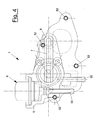
- Figure 4 is a plan view from above of the pump group according to the present invention; and
- Figure 5 is a plan view from above of the pump group according to the present invention, partially in section.
-
- With reference to the figures, a fuel pump group 1 according to the present invention, for fuel feeding systems for four-stroke injection engines, is shown.
- As can be seen in figure 1, the pump group 1 is mechanical and according to a preferred embodiment, it is mounted at the
power unit 100 and in particular on thehead 51 of the power unit itself. - The pump group 1, again according to the preferred embodiment shown in figures 1-5, has a
containment body 50 made by die casting, amechanical feeding pump 2, aninjector 8 positioned inside arelative housing 4 and apressure regulator 6 positioned inside therelative housing 5. - The
pump 2 and theinjector 8 are placed in communication by means of aconnection duct 7 made inside asupport 9 for the injector screwed onto thecontainment body 50. - The
containment body 50, as stated previously, is mounted directly on thehead 51 of thepower unit 100. - In detail, the
containment body 50 is mounted on thehead 51 of thepower unit 100 by means ofscrews 52, placing aheat insulation header 10 between thehead 51 of thepower unit 100 and thecontainment body 50. - The
pump 2, as can be seen better in figure 1, takes the alternating movement from adesmodromic system 11 formed from an eccentric 12, arranged on the cam axis of the engine, and from a forkedlever 13 engaged with the eccentric 12, as shall be illustrated hereafter. - The forked
lever 13, again as can be seen in the figures, is rotatably pivoted, at 14, through a suitable clamping screw, to thehead 51 of thepower unit 100. - The
pump 2 consists of a cylinder 16 -piston 15 group , in which thepiston 15 is actuated by ashaft 18 activated by the forkedlever 13. - In detail, the
forked lever 13 has a projection that abuts against the base of theshaft 18 to guide the stroke of theshaft 18 and, consequently, of thepiston 15 with respect to thecylinder 16. The contact between theshaft 18 and thefork 13 is ensured by suitable elastic means, such as ahelical spring 19. - The lubrication of the coupling between
cylinder 16 andpiston 15 is ensured by a suitable oil circuit that sends pressurised oil into athroat 17 made, for such a purpose, in the lower portion of thecylinder 16. - The
pump 2, as can be seen more clearly in figure 3, also comprises, at the top, adelivery chamber 28 connected, at the top, to theconnection duct 7 and, at the bottom, to the cylinder 16 -piston 15 group . - Through the
connection duct 7, thedelivery chamber 28 is placed in communication with theinjector 8. - In particular, an automatic cylindrical valve 40 is arranged between the cylinder 16 -
piston 15 group and thedelivery chamber 28. This valve is made up of afixed part 26 and a mobile part 25. - The valve 40 and in particular its mobile part 25 is able to lift up under the action of the
piston 15 to make the fuel flow throughsuitable holes 33 to thedelivery chamber 28 and from here to theinjector 8. - The number, position and arrangement of the
holes 33 can vary according to the delivery curve that one wishes to obtain. - During the downward stroke of the
piston 15, suitable elastic means, such as acounter spring 27, ensure that the valve 40 closes. - The feeding of the fuel to the
pump 2 is obtained through theholes 20 made in the high part of thecylinder 16. -
Such holes 20, which interface with thechamber 21 of thepump body 2, are connected to the fuel reservoir, not shown, through theduct 22. - The positioning of the
holes 20 with respect to thepiston 15 determines the suction-delivery diagram of thepump 2. - The
delivery chamber 28, as can be seen more clearly in figure 5, through theopening 35, thethroat 30 andsuitable holes 29, also communicates with apressure regulator 6 suitable for ensuring the correct pressure of the fuel going into theinjector 8. - The pump group 1 outlined above allows an automatic variation of the impulse flow rate to be carried out according to the number of revolutions of the engine.
- The stroke of the piston and in particular its speed, all other things being equal, is indeed directly connected to the drive shaft and therefore to its number of revolutions. This characteristic is used to have the maximum impulse flow rate at low operating speeds, in order to pressurise the unit quickly during the starting step, and optimal impulse flow rate values, in other words lower values, when the engine works at normal operating speed. The pump group according to the present invention may or may not foresee a fuel recirculation circuit, made by means of the
throat 23, formed on thecylinder 16, with the purpose of recovering the pressurised petrol that drips from the cylinder 16 -piston 15 coupling during the delivery step and injecting it through thesuitable hole 24 into thesuction chamber 21. - In the case of recirculation being present, as shown in figures 1-5, it should be noted that the amount of petrol necessary for recirculation must not be excessive in order to avoid overheating that would cause the deterioration of the fuel still present in the reservoir.
- In such a case, in line with the pressure regulator there is an outlet fitting 32 (figure 1) of the fuel necessary for the return of the petrol into the reservoir during recirculation.
- In an alternative embodiment that is not shown and that is not equipped with recirculation, the
outlet fitting 32 is not present, therefore the feeding unit is provided with just one pipe for feeding from the reservoir to thepump 2, without the return branch. - In such a case, the outlet of the
regulator 6 must be connected, directly or indirectly, with thechamber 21 through a duct that can be outside or inside thepump 2. - In the case of a feeding system for an indirect injection four-stroke engine the
containment group 50 also comprises anair intake duct 3 on which it is foreseen to mount anelastic fitting 34 for the attachment of the throttled body, see figures 1 and 2. - Although in the present description a pump group has been illustrated installed on the head of the engine group, it should however be understood that the pump group could also be installed in another area of the power unit, possibly replacing or integrating the desmodromic actuation system with another system suitable for the purpose.
- The pump group according to the present invention allows most of the components to be grouped together close to the throttled body of the engine, and also, unlike analogous systems adopted on four-wheeled vehicles, it has zero absorption of electricity and low cost and is small in size and, therefore, it has low impact upon the lay-out of the vehicle and finally it does not have high pressure pipes.
- The present invention has been described for illustrating but not limiting purposes according to its preferred embodiments, but it should be understood that variations and/or modifications can be made by men skilled in the art without for this reason departing from the relative scope of protection, as defined by the attached claims.
Claims (10)
- Pump group (1) for fuel feeding systems for four-stroke injection engines characterised in that said pump group (1) is mechanical and is mounted at the power unit (100) to carry out feeding with variable flow rate according to the revolutions of the engine.
- Pump group (1) according to claim 1, characterised in that it is mounted on the head (51) of the power unit (100).
- Pump group (1) according to claim 1 or 2, characterised in that it comprises a containment body (50) comprising at least one injector (8), positioned inside a relative housing (4), a mechanical feeding pump (2) and a connection duct (7) between said pump (2) and said injector (8).
- Pump group (1) according to claim 3, characterised in that said containment body (50) comprises reversible fastening means (52) to the head (51) of the power unit (100).
- Pump group (1) according to claim 3 or 4, characterised in that said pump (2) is actuated in an alternating manner by a desmodromic system (11).
- Pump group (1) according to claim 5, characterised in that said desmodromic system (11) comprises an eccentric (12), arranged on the cam axis of the power unit, engaged with a forked lever (13) hinged to the head (51) of said power unit (100).
- Pump group (1) according to claim 6, characterised in that said pump (2) comprises a cylinder (16) - piston (15) group actuated by a shaft (18) activated by said forked lever (13).
- Pump group (1) according to any one of claims 3 to 7, characterised in that said pump (2) comprises a delivery chamber (28) connected to said connection duct (7) and to an automatic valve (40) suitable for lifting up under the thrust of said piston (15) to make the fuel flow to said delivery chamber (28) and for going back down into position under the action of elastic means (27).
- Pump group (1) according to claims 8 and 7, characterised in that said pump (2) also comprises at least one hole for filling said pump (2) in communication with a feeding duct (22) coming from the reservoir.
- Pump group (1) according to any one of the previous claims from 3 to 9, characterised in that said containment body (50) comprises a fitting (34) for a throttled body.
Applications Claiming Priority (2)
| Application Number | Priority Date | Filing Date | Title |
|---|---|---|---|
| IT000032A ITMI20040032A1 (en) | 2004-01-14 | 2004-01-14 | VARIABLE FLOW FUEL PUMP GROUP |
| ITMI20040032 | 2004-01-14 |
Publications (3)
| Publication Number | Publication Date |
|---|---|
| EP1555428A2 true EP1555428A2 (en) | 2005-07-20 |
| EP1555428A3 EP1555428A3 (en) | 2007-06-06 |
| EP1555428B1 EP1555428B1 (en) | 2010-03-03 |
Family
ID=34611239
Family Applications (1)
| Application Number | Title | Priority Date | Filing Date |
|---|---|---|---|
| EP04078579A Not-in-force EP1555428B1 (en) | 2004-01-14 | 2004-12-31 | Fuel pump group with variable flow rate |
Country Status (7)
| Country | Link |
|---|---|
| EP (1) | EP1555428B1 (en) |
| CN (1) | CN100419250C (en) |
| AT (1) | ATE459800T1 (en) |
| DE (1) | DE602004025787D1 (en) |
| ES (1) | ES2342383T3 (en) |
| IT (1) | ITMI20040032A1 (en) |
| TW (1) | TW200525083A (en) |
Families Citing this family (1)
| Publication number | Priority date | Publication date | Assignee | Title |
|---|---|---|---|---|
| DE102013220739A1 (en) * | 2013-10-14 | 2015-04-16 | Continental Automotive Gmbh | pressure regulator |
Citations (3)
| Publication number | Priority date | Publication date | Assignee | Title |
|---|---|---|---|---|
| GB2195708A (en) * | 1986-09-30 | 1988-04-13 | Daimler Benz Ag | Magnetic valve controlled injection device consisting of pump and nozzle for air compression internal combustion engines |
| WO1997025530A1 (en) * | 1996-01-09 | 1997-07-17 | Daimler-Benz Aktiengesellschaft | Plug-in pump for internal combustion engine |
| US6109894A (en) * | 1994-11-07 | 2000-08-29 | Chatelain; Michel | Dual piston pump device for feeding two independent liquids |
Family Cites Families (1)
| Publication number | Priority date | Publication date | Assignee | Title |
|---|---|---|---|---|
| DE4138290A1 (en) * | 1991-11-21 | 1993-05-27 | Kloeckner Humboldt Deutz Ag | INTERNAL COMBUSTION ENGINE |
-
2004
- 2004-01-14 IT IT000032A patent/ITMI20040032A1/en unknown
- 2004-12-31 EP EP04078579A patent/EP1555428B1/en not_active Not-in-force
- 2004-12-31 DE DE602004025787T patent/DE602004025787D1/en active Active
- 2004-12-31 ES ES04078579T patent/ES2342383T3/en active Active
- 2004-12-31 AT AT04078579T patent/ATE459800T1/en active
-
2005
- 2005-01-06 TW TW094100314A patent/TW200525083A/en unknown
- 2005-01-14 CN CNB2005100040955A patent/CN100419250C/en not_active Expired - Fee Related
Patent Citations (3)
| Publication number | Priority date | Publication date | Assignee | Title |
|---|---|---|---|---|
| GB2195708A (en) * | 1986-09-30 | 1988-04-13 | Daimler Benz Ag | Magnetic valve controlled injection device consisting of pump and nozzle for air compression internal combustion engines |
| US6109894A (en) * | 1994-11-07 | 2000-08-29 | Chatelain; Michel | Dual piston pump device for feeding two independent liquids |
| WO1997025530A1 (en) * | 1996-01-09 | 1997-07-17 | Daimler-Benz Aktiengesellschaft | Plug-in pump for internal combustion engine |
Also Published As
| Publication number | Publication date |
|---|---|
| ATE459800T1 (en) | 2010-03-15 |
| ITMI20040032A1 (en) | 2004-04-14 |
| CN1644912A (en) | 2005-07-27 |
| EP1555428A3 (en) | 2007-06-06 |
| DE602004025787D1 (en) | 2010-04-15 |
| CN100419250C (en) | 2008-09-17 |
| EP1555428B1 (en) | 2010-03-03 |
| TW200525083A (en) | 2005-08-01 |
| ES2342383T3 (en) | 2010-07-06 |
Similar Documents
| Publication | Publication Date | Title |
|---|---|---|
| US5975032A (en) | Engine cooling system | |
| EP2138710B1 (en) | Saddle-straddling type motor vehicle | |
| EP1770273B2 (en) | Multi-cylinder engine | |
| CN101598046B (en) | Lubricating system for air-cooled general-purpose engine | |
| JP2002161813A (en) | Fuel system of four cycle engine for outboard engine | |
| JPH0794803B2 (en) | Lubricating oil passage structure of engine equipped with horizontal cylinder and outboard motor equipped with the engine | |
| US6276340B1 (en) | Engine injection control | |
| US7383811B2 (en) | Fuel injection system for engine | |
| US6912996B2 (en) | Engine with fuel injection system | |
| US6321711B1 (en) | Fuel supply system for a direct injected outboard engine | |
| CN106523226B (en) | High-pressure common rail system of diesel engine | |
| EP1555428B1 (en) | Fuel pump group with variable flow rate | |
| US5243945A (en) | Fuel injection system for the internal combustion engine | |
| US20010029927A1 (en) | Fuel supply system for a direct injected outboard engine | |
| JP3528494B2 (en) | Outboard fuel supply system | |
| US6830029B2 (en) | Fuel supply device for outboard motor | |
| JP5578050B2 (en) | Engine oil pump arrangement structure | |
| WO2018029572A1 (en) | An intake system for a two wheeled vehicle | |
| JP4586549B2 (en) | Direct injection multi-cylinder engine | |
| JP4126881B2 (en) | Intake control device for fuel injection engine | |
| US6691673B2 (en) | Fuel supply device for outboard motor | |
| JP2008208786A (en) | Oiling device for engine oil of motorcycle and repair method for oiling mechanism | |
| JP6308969B2 (en) | Small vehicle fuel injection device arrangement structure | |
| JP4224417B2 (en) | Vertical engine | |
| JP2003262172A (en) | Injection pump, and fuel supply device for diesel engine provided with the same |
Legal Events
| Date | Code | Title | Description |
|---|---|---|---|
| PUAI | Public reference made under article 153(3) epc to a published international application that has entered the european phase |
Free format text: ORIGINAL CODE: 0009012 |
|
| AK | Designated contracting states |
Kind code of ref document: A2 Designated state(s): AT BE BG CH CY CZ DE DK EE ES FI FR GB GR HU IE IS IT LI LT LU MC NL PL PT RO SE SI SK TR |
|
| AX | Request for extension of the european patent |
Extension state: AL BA HR LV MK YU |
|
| PUAL | Search report despatched |
Free format text: ORIGINAL CODE: 0009013 |
|
| AK | Designated contracting states |
Kind code of ref document: A3 Designated state(s): AT BE BG CH CY CZ DE DK EE ES FI FR GB GR HU IE IS IT LI LT LU MC NL PL PT RO SE SI SK TR |
|
| AX | Request for extension of the european patent |
Extension state: AL BA HR LV MK YU |
|
| RIC1 | Information provided on ipc code assigned before grant |
Ipc: F02M 69/14 20060101ALI20070502BHEP Ipc: F02M 69/04 20060101ALI20070502BHEP Ipc: F02B 75/16 20060101ALI20070502BHEP Ipc: F02B 67/04 20060101ALI20070502BHEP Ipc: F02M 69/02 20060101ALI20070502BHEP Ipc: F02M 59/46 20060101ALI20070502BHEP Ipc: F02M 59/10 20060101AFI20050421BHEP Ipc: F02M 61/14 20060101ALI20070502BHEP Ipc: F02M 53/00 20060101ALI20070502BHEP Ipc: F02M 59/44 20060101ALI20070502BHEP |
|
| 17P | Request for examination filed |
Effective date: 20071112 |
|
| AKX | Designation fees paid |
Designated state(s): AT BE BG CH CY CZ DE DK EE ES FI FR GB GR HU IE IS IT LI LT LU MC NL PL PT RO SE SI SK TR |
|
| 17Q | First examination report despatched |
Effective date: 20080131 |
|
| GRAP | Despatch of communication of intention to grant a patent |
Free format text: ORIGINAL CODE: EPIDOSNIGR1 |
|
| GRAS | Grant fee paid |
Free format text: ORIGINAL CODE: EPIDOSNIGR3 |
|
| GRAA | (expected) grant |
Free format text: ORIGINAL CODE: 0009210 |
|
| AK | Designated contracting states |
Kind code of ref document: B1 Designated state(s): AT BE BG CH CY CZ DE DK EE ES FI FR GB GR HU IE IS IT LI LT LU MC NL PL PT RO SE SI SK TR |
|
| REG | Reference to a national code |
Ref country code: GB Ref legal event code: FG4D |
|
| REG | Reference to a national code |
Ref country code: CH Ref legal event code: EP |
|
| REG | Reference to a national code |
Ref country code: IE Ref legal event code: FG4D |
|
| REF | Corresponds to: |
Ref document number: 602004025787 Country of ref document: DE Date of ref document: 20100415 Kind code of ref document: P |
|
| REG | Reference to a national code |
Ref country code: NL Ref legal event code: VDEP Effective date: 20100303 |
|
| REG | Reference to a national code |
Ref country code: ES Ref legal event code: FG2A Ref document number: 2342383 Country of ref document: ES Kind code of ref document: T3 |
|
| PG25 | Lapsed in a contracting state [announced via postgrant information from national office to epo] |
Ref country code: LT Free format text: LAPSE BECAUSE OF FAILURE TO SUBMIT A TRANSLATION OF THE DESCRIPTION OR TO PAY THE FEE WITHIN THE PRESCRIBED TIME-LIMIT Effective date: 20100303 |
|
| LTIE | Lt: invalidation of european patent or patent extension |
Effective date: 20100303 |
|
| PG25 | Lapsed in a contracting state [announced via postgrant information from national office to epo] |
Ref country code: SI Free format text: LAPSE BECAUSE OF FAILURE TO SUBMIT A TRANSLATION OF THE DESCRIPTION OR TO PAY THE FEE WITHIN THE PRESCRIBED TIME-LIMIT Effective date: 20100303 Ref country code: PL Free format text: LAPSE BECAUSE OF FAILURE TO SUBMIT A TRANSLATION OF THE DESCRIPTION OR TO PAY THE FEE WITHIN THE PRESCRIBED TIME-LIMIT Effective date: 20100303 Ref country code: FI Free format text: LAPSE BECAUSE OF FAILURE TO SUBMIT A TRANSLATION OF THE DESCRIPTION OR TO PAY THE FEE WITHIN THE PRESCRIBED TIME-LIMIT Effective date: 20100303 |
|
| PG25 | Lapsed in a contracting state [announced via postgrant information from national office to epo] |
Ref country code: EE Free format text: LAPSE BECAUSE OF FAILURE TO SUBMIT A TRANSLATION OF THE DESCRIPTION OR TO PAY THE FEE WITHIN THE PRESCRIBED TIME-LIMIT Effective date: 20100303 Ref country code: BE Free format text: LAPSE BECAUSE OF FAILURE TO SUBMIT A TRANSLATION OF THE DESCRIPTION OR TO PAY THE FEE WITHIN THE PRESCRIBED TIME-LIMIT Effective date: 20100303 Ref country code: CY Free format text: LAPSE BECAUSE OF FAILURE TO SUBMIT A TRANSLATION OF THE DESCRIPTION OR TO PAY THE FEE WITHIN THE PRESCRIBED TIME-LIMIT Effective date: 20100303 Ref country code: GR Free format text: LAPSE BECAUSE OF FAILURE TO SUBMIT A TRANSLATION OF THE DESCRIPTION OR TO PAY THE FEE WITHIN THE PRESCRIBED TIME-LIMIT Effective date: 20100604 Ref country code: NL Free format text: LAPSE BECAUSE OF FAILURE TO SUBMIT A TRANSLATION OF THE DESCRIPTION OR TO PAY THE FEE WITHIN THE PRESCRIBED TIME-LIMIT Effective date: 20100303 Ref country code: RO Free format text: LAPSE BECAUSE OF FAILURE TO SUBMIT A TRANSLATION OF THE DESCRIPTION OR TO PAY THE FEE WITHIN THE PRESCRIBED TIME-LIMIT Effective date: 20100303 Ref country code: SE Free format text: LAPSE BECAUSE OF FAILURE TO SUBMIT A TRANSLATION OF THE DESCRIPTION OR TO PAY THE FEE WITHIN THE PRESCRIBED TIME-LIMIT Effective date: 20100303 |
|
| PG25 | Lapsed in a contracting state [announced via postgrant information from national office to epo] |
Ref country code: BG Free format text: LAPSE BECAUSE OF FAILURE TO SUBMIT A TRANSLATION OF THE DESCRIPTION OR TO PAY THE FEE WITHIN THE PRESCRIBED TIME-LIMIT Effective date: 20100603 Ref country code: IS Free format text: LAPSE BECAUSE OF FAILURE TO SUBMIT A TRANSLATION OF THE DESCRIPTION OR TO PAY THE FEE WITHIN THE PRESCRIBED TIME-LIMIT Effective date: 20100703 Ref country code: SK Free format text: LAPSE BECAUSE OF FAILURE TO SUBMIT A TRANSLATION OF THE DESCRIPTION OR TO PAY THE FEE WITHIN THE PRESCRIBED TIME-LIMIT Effective date: 20100303 Ref country code: CZ Free format text: LAPSE BECAUSE OF FAILURE TO SUBMIT A TRANSLATION OF THE DESCRIPTION OR TO PAY THE FEE WITHIN THE PRESCRIBED TIME-LIMIT Effective date: 20100303 |
|
| PLBE | No opposition filed within time limit |
Free format text: ORIGINAL CODE: 0009261 |
|
| STAA | Information on the status of an ep patent application or granted ep patent |
Free format text: STATUS: NO OPPOSITION FILED WITHIN TIME LIMIT |
|
| PG25 | Lapsed in a contracting state [announced via postgrant information from national office to epo] |
Ref country code: DK Free format text: LAPSE BECAUSE OF FAILURE TO SUBMIT A TRANSLATION OF THE DESCRIPTION OR TO PAY THE FEE WITHIN THE PRESCRIBED TIME-LIMIT Effective date: 20100303 Ref country code: PT Free format text: LAPSE BECAUSE OF FAILURE TO SUBMIT A TRANSLATION OF THE DESCRIPTION OR TO PAY THE FEE WITHIN THE PRESCRIBED TIME-LIMIT Effective date: 20100705 |
|
| PGFP | Annual fee paid to national office [announced via postgrant information from national office to epo] |
Ref country code: AT Payment date: 20101129 Year of fee payment: 7 Ref country code: FR Payment date: 20101224 Year of fee payment: 7 |
|
| 26N | No opposition filed |
Effective date: 20101206 |
|
| PGFP | Annual fee paid to national office [announced via postgrant information from national office to epo] |
Ref country code: GB Payment date: 20101229 Year of fee payment: 7 |
|
| PGFP | Annual fee paid to national office [announced via postgrant information from national office to epo] |
Ref country code: DE Payment date: 20101230 Year of fee payment: 7 |
|
| PG25 | Lapsed in a contracting state [announced via postgrant information from national office to epo] |
Ref country code: MC Free format text: LAPSE BECAUSE OF NON-PAYMENT OF DUE FEES Effective date: 20101231 |
|
| PGFP | Annual fee paid to national office [announced via postgrant information from national office to epo] |
Ref country code: ES Payment date: 20110120 Year of fee payment: 7 |
|
| REG | Reference to a national code |
Ref country code: CH Ref legal event code: PL |
|
| PG25 | Lapsed in a contracting state [announced via postgrant information from national office to epo] |
Ref country code: CH Free format text: LAPSE BECAUSE OF NON-PAYMENT OF DUE FEES Effective date: 20101231 Ref country code: IE Free format text: LAPSE BECAUSE OF NON-PAYMENT OF DUE FEES Effective date: 20101231 Ref country code: LI Free format text: LAPSE BECAUSE OF NON-PAYMENT OF DUE FEES Effective date: 20101231 |
|
| PG25 | Lapsed in a contracting state [announced via postgrant information from national office to epo] |
Ref country code: IT Free format text: LAPSE BECAUSE OF NON-PAYMENT OF DUE FEES Effective date: 20101231 |
|
| GBPC | Gb: european patent ceased through non-payment of renewal fee |
Effective date: 20111231 |
|
| REG | Reference to a national code |
Ref country code: FR Ref legal event code: ST Effective date: 20120831 |
|
| PG25 | Lapsed in a contracting state [announced via postgrant information from national office to epo] |
Ref country code: LU Free format text: LAPSE BECAUSE OF NON-PAYMENT OF DUE FEES Effective date: 20101231 Ref country code: HU Free format text: LAPSE BECAUSE OF FAILURE TO SUBMIT A TRANSLATION OF THE DESCRIPTION OR TO PAY THE FEE WITHIN THE PRESCRIBED TIME-LIMIT Effective date: 20100904 |
|
| REG | Reference to a national code |
Ref country code: DE Ref legal event code: R119 Ref document number: 602004025787 Country of ref document: DE Effective date: 20120703 |
|
| PG25 | Lapsed in a contracting state [announced via postgrant information from national office to epo] |
Ref country code: GB Free format text: LAPSE BECAUSE OF NON-PAYMENT OF DUE FEES Effective date: 20111231 Ref country code: TR Free format text: LAPSE BECAUSE OF FAILURE TO SUBMIT A TRANSLATION OF THE DESCRIPTION OR TO PAY THE FEE WITHIN THE PRESCRIBED TIME-LIMIT Effective date: 20100303 Ref country code: DE Free format text: LAPSE BECAUSE OF NON-PAYMENT OF DUE FEES Effective date: 20120703 |
|
| REG | Reference to a national code |
Ref country code: AT Ref legal event code: MM01 Ref document number: 459800 Country of ref document: AT Kind code of ref document: T Effective date: 20111231 |
|
| PG25 | Lapsed in a contracting state [announced via postgrant information from national office to epo] |
Ref country code: AT Free format text: LAPSE BECAUSE OF NON-PAYMENT OF DUE FEES Effective date: 20111231 |
|
| PG25 | Lapsed in a contracting state [announced via postgrant information from national office to epo] |
Ref country code: FR Free format text: LAPSE BECAUSE OF NON-PAYMENT OF DUE FEES Effective date: 20120102 |
|
| REG | Reference to a national code |
Ref country code: ES Ref legal event code: FD2A Effective date: 20130703 |
|
| PG25 | Lapsed in a contracting state [announced via postgrant information from national office to epo] |
Ref country code: ES Free format text: LAPSE BECAUSE OF NON-PAYMENT OF DUE FEES Effective date: 20120101 |