EP1555395B1 - Gassteuerungssystem für Motorprüfstand - Google Patents
Gassteuerungssystem für Motorprüfstand Download PDFInfo
- Publication number
- EP1555395B1 EP1555395B1 EP04293145A EP04293145A EP1555395B1 EP 1555395 B1 EP1555395 B1 EP 1555395B1 EP 04293145 A EP04293145 A EP 04293145A EP 04293145 A EP04293145 A EP 04293145A EP 1555395 B1 EP1555395 B1 EP 1555395B1
- Authority
- EP
- European Patent Office
- Prior art keywords
- control
- signal
- angular position
- tra
- interface
- Prior art date
- Legal status (The legal status is an assumption and is not a legal conclusion. Google has not performed a legal analysis and makes no representation as to the accuracy of the status listed.)
- Expired - Lifetime
Links
Images




Classifications
-
- F—MECHANICAL ENGINEERING; LIGHTING; HEATING; WEAPONS; BLASTING
- F01—MACHINES OR ENGINES IN GENERAL; ENGINE PLANTS IN GENERAL; STEAM ENGINES
- F01D—NON-POSITIVE DISPLACEMENT MACHINES OR ENGINES, e.g. STEAM TURBINES
- F01D21/00—Shutting-down of machines or engines, e.g. in emergency; Regulating, controlling, or safety means not otherwise provided for
- F01D21/003—Arrangements for testing or measuring
Definitions
- the invention relates generally to turbomachines. It applies in particular to aircraft engines.
- the present invention improves the situation.
- the invention proposes a gas control device for an aircraft turbomachine, of the type comprising a control assembly, capable of acting on the native control of the turbomachine, as a function of a manual input defined by a control member, in wherein the control member is arranged to output a joystick angular position signal in the form of a voltage, in particular a DC voltage.
- the device further comprises an actuator module adapted to receive as input the transformed angular position signal and to output a native control for hydromechanically controlled turbomachines, the automaton being adapted to control the actuator module comprising a motor and gearbox.
- the actuator module is able to act electromechanically on a lever of a turbomachine regulator with hydromechanical control and, in addition, the automaton is adapted to control the lever of the actuator module.
- the interface is capable, from an excitation signal transmitted by a turbomachine regulator, of converting an angular position signal transformed into two sinusoidal signals transmitted to the turbomachine regulator whose native control is sinusoidal type signals. .
- the transformed angular position signal comprises either a linear signal or two trigonometric signals.
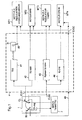
- the figure 1 is a schematic diagram of a test bench capable of working on different types of engines, illustrated.
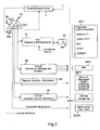
- the figure 2 is the same diagram of principle, a little more detailed, but without showing the engines.
- control member may include a physical controller PM, to ensure proper gas control.
- this lever PM acts on the lever CL by means of a position control 2, called "servo-joystick".
- CL lever is associated with a potentiometric type angular position sensor CL1.
- This angular position, or its copy, is transmitted electrically in the form of an analog position signal CLS1, in particular a continuous potentiometric voltage signal, to a control assembly 4, to which we will return.
- Reference MT1 designates a motor with gas control by hydromechanical regulation. It can be one of the following engines: CFM56-2, CFM56-3, JT8D9 to JT8D17, M53, ATAR, LARZAC, all manufactured by the Applicant.
- the input member of the throttle control, on the engine side, is then a lever 89.
- the control assembly 4 comprises an electronic spool 41 (TEG), which acts on an actuator 81, which controls turn the lever 89.
- electronic drawer means a module that can be in the form of a drawer receiving electronic racks and able to act on actuator type means, regulator or others.
- Reference MT2 designates a motor with electric voltage control, such as for example the M88 model of the Applicant.
- the control unit 4 comprises a specific drawer of this motor 42 (TSM88), which is responsible for providing the appropriate voltages.
- the reference MT3 designates a throttle-controlled throttle-type signaling motor, in particular for a so-called "FADEC"("Full Authority Digital Engine Control") regulator, such as for example the CFM56-5A / 5B / 5C engines.
- FADEC Frull Authority Digital Engine Control
- Such engines can operate either in ECU ("Engine Control Unit”) or EEC ("Electronic Engine Control") mode.
- the FADEC controller basically involves a redundant calculator.
- the reference MT3 also covers the motors whose control computer is not redundant, like the so-called PMC ("Power Management Control") computers, for example the CF6 80 C2 PMC / PMUX engine.
- PMC Power Management Control
- control assembly 4 comprises a stage 43, which can operate by simply copying CLS2 signals from the CL lever, to the extent that it is also output type synchroresolver.
- Reference MT4 denotes a throttle-controlled throttle control motor, such as, for example, the CF6 80 E1 FADEC, CF680 C2 FADEC or CFM 56-7B engine of the Applicant.
- control unit 4 comprises a specific interface 44 (ISCF6), which can operate by adaptation of the signals from the CL lever, to the extent that it is output type synchro-resolver.
- ISCF6 specific interface 44
- elements 1 and 4 are placed in the control room. If necessary, the actuator 89 is placed on the reactor or in the immediate vicinity.
- actuators are possible depending on the type of reactor (in particular: travel, engine torque and idling torque)
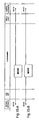
- the figure 7 illustrates more particularly the case of the resolver interface intended to work with a signal redundancy regulator.
- this box comprises two resolver interfaces 70-1 and 70-2 each receiving as input the angle reference signal of the controller.
- the latter comprises two analog outputs each connected to a different resolver interface.
- the resolver interface receiving two trigonometric type signals may be an electronic card comprising conventional components providing the functions of multiplication of analog signals.
- This man-machine interface also makes it possible to modify the angular position of the joystick by sending appropriate commands to the controller.
- the operator can click virtual buttons M ++, M +, M- and M - - presented on the screen in order to increase or decrease the angular position of the joystick from a value displayed on the screen. screen. It can also directly enter the value of the desired angular position.
- the virtual button M ++ has a step of incrementation (or slope) greater than the step of incrementing the virtual button M +. The same goes for the buttons M- and M - -.
- the figure 9 represents other virtual buttons assigned to the action of bringing the joystick on the stop Idle Flying (virtual button RV), to the action of bringing the handle on the stop Slow motion Sol (virtual button RS), to the indication that the operator skips the stop (virtual button B).
- the position of the indicators I which can move on graduated scales indicate the values of the 4 stops.
- the operator can click on virtual buttons M ++, M +, M- and M - - presented on the screen to increase or decrease the current setpoint C.
- the values of the ground and flight idle can also be modified from the same maneuvers by the operator.
- these values are transmitted to the controller 4 by a PC type computer called federator and used as a gateway between the controller and the pilot screen.
- the PLC 4 transmits these values to the physical controller 1.
- the parameters of the control member comprise the travel of the control member, the position of the stops of the joystick, the value of the desired angular position, the acceleration by angular unit and the deceleration by angular unit associated with either the angular input by the operator, either to the virtual buttons M ++, M +, M-, M- - (which corresponds to the incrementation step), or to the position of each stop.
- the selection of the engine control law by the operator is to select the type of engine (or turbomachine) wanted.
- the selected motor makes it possible to send to an electronic drawer the expected type of signal, the drawer 41 then being able to act on the actuator 81.
- the Figures 11 to 22 illustrate an example of implementation of the automaton in the form of logic circuits.
- the human-machine interface type operator panel for example a graphical interface connected to the controller, allows an operator to enter data to thus perform tests on a selected engine on the test bench. This graphical interface also allows the operator to follow the evolution of the current test.
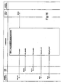
- the figure 10 illustrates the meaning of the symbols used in the logic circuits of Figures 11 to 22 .
- the symbol 100 associates two inputs into an output signal.
- the symbol 108 illustrates a setting 1 of the input signal.
- the symbol 110 illustrates a setting 0 of the input signal.
- Symbols 112 and 114 illustrate logical flip-flops.
- Symbols 114 and 116 illustrate a trigger on a rising edge and a falling edge of a signal.
- Symbol 120 illustrates a timing of a signal.
- Symbol 124 illustrates the equality between the input and output signal.
- the symbol 126 checks the superiority between a main signal and a value and delivers the main signal as an output signal.
- the symbol 128 verifies the superiority or equality between a main signal and a value and delivers the main signal as an output signal.
- the symbol 130 checks the inferiority between a main signal and a value and delivers the main signal as an output signal.
- the symbol 132 checks the inferiority or equality between a main signal and a value and delivers the main signal as an output signal.
- the symbol 134 checks the difference between a main signal and a value and outputs the main signal as the output signal.
- the symbol 136 adds two input signals and outputs a corresponding output signal.
- the symbol 138 multiplies two input signals and outputs a corresponding output signal.
- Symbol 142 divides two input signals and outputs a corresponding output signal. Acronyms are also used to designate logic circuits such as the initials MOVE which designates an instruction to copy a memory into another memory.
- an operator who wishes to perform a test must choose a motor among the proposed engines, enter and validate the minimum and maximum angles of the joystick, and start the test.
- FIG. 13-A and 13-B respectively illustrate voltage fault detection circuits at cards 1 and 2 of the PLC.
- the input E0.0, respectively E0.1 of the PLC is activated as soon as a voltage fault is detected at the level of the card 1, respectively 2.
- These logic circuits provide a signal on the outputs M153.0 and M153 .1 the PLC warning of current faults.
- Other logic circuits allow the detection of specific faults of the PLC.
- the figure 11-A has a fault acknowledgment by an operator entering the MW104 command.
- the fault acknowledgment information is presented by the interface (MW104 and MW152) and the M4.0 output of the controller resets the test and allows it to be restarted.
- the MOVE boxes are instructions for copying a memory into another memory, here a copy of the information for an on-screen display.
- the figure 11-B illustrates the acquisition of the minimum angle of the joystick.
- An operator enters a value of the minimum angle of the joystick to be applied between 0 ° and 360 ° (command MW108). This value must be different from 0 and is associated with an average value MW150 which must be different from 256 to validate the value of the minimum angle of the joystick.
- the voltage signal on the M4.1 output of the controller represents the validation of the acquisition of the minimum angle of the joystick.
- the figure 11-C illustrates the acquisition of the maximum angle of the joystick.
- An operator enters a value of the maximum angle of the joystick to be applied between 0 ° and 360 ° (command MW106). This value must be different from 0 and is associated with the average value MW150 which must be different from 256 to validate the value of the maximum angle of the joystick.
- the voltage signal on the output of the M4.2 PLC represents the validation of the acquisition of the maximum angle of the joystick.
- the Figures 12-A and 12-B illustrate the logic circuits allowing the display on the graphical interface of the value MW106 of the maximum angle of the joystick and the value MW108 of the minimum angle of the joystick once validated as illustrated on the Figure 11-B and 11-C .
- the input 0 values of the MOVE boxes are used for initialization.
- the angular movement of the joystick corresponds to a "law lever". This travel is selected as described above by the user.
- FIGS. 14-A to 14-E each illustrate a logic circuit used for one of the five motors that the operator can choose by the command MW100.
- the motor can only be selected when the test state is at a standstill: the value of the MW 102 start / stop command is at 0 when the state is at a standstill, a value that can be modified by operator input.
- the command MW100 can be equal to an integer of 1 to 5 to designate the motor chosen by the operator, the motors being numbered from 1 to 5 in the examples of the figures 14 .
- the operator can enter the values of the minimum and maximum of the angular range of the selected motor, the angular range varying from -360 ° to 360 °.
- These controls are MD170 and MD174 for Engine 1, MD180 and MD184 for Engine 2, MD190 and MD194 for Engine 3, MD200 and MD204 for Engine 4, MD210 and MD214 for Engine 5.
- the angular range related to the choice of motor is called "motor control law” or "motor law”.
- On / off command MW102 has been set to 1.
- the logic circuit for which MW100 1 is activated.
- the controller collects output voltage values MD158 and MD162 associated with the minimum and maximum angle values of the selected motor.
- the voltage values MD158 and MD162 corresponding to the minimum and maximum angle values of the selected motor are used as inputs by the PLC on the Figures 15-A and 15-B . These voltage values are recopied in memory by the MOVE box, which makes it possible to obtain the voltage values corresponding to the dummy values of the minimum and maximum angles MD110 and MD114 of the lever for the chosen motor.
- the angular range of the joystick is modified according to the selected motor and the associated control law.
- the logic circuit of the automaton of the figure 16 converts the voltage value of the potentiometer on the PEW controller 304 to a voltage value MD154 corresponding to the angle of the current joystick. This conversion is made from the voltage range of the potentiometer, the voltage values corresponding to the values of the maximum and minimum real angles of the joystick, the voltage values corresponding to the dummy values of the minimum and maximum angles MD110 and MD114 of the joystick for the engine chosen.
- FIGS. 17-A to 17-C illustrate the logic circuits leading to the calculation of the angle setpoint in degrees and then in radian.
- the figure 17-A corresponds to an initialization circuit before calculating the new angle setpoint.
- the output MD20 is a voltage representing a value in degrees.
- the logical circuit of the figure 17-B allows to obtain at the output the value of the angle of the joystick in degrees MD20.
- the figure 17-C illustrates the conversion of the MD20 value into a MD24 radian angle by the multiplication of a factor ⁇ / 180.
- the automaton can propose, as indicated in the description above, to the resolver interface, a setpoint angle value which is then transformed into two sine and cosine values. It is also possible to propose an automaton which delivers as output values, the cosine and the sine of the setpoint angle.
- the figures 18 illustrate an automaton proposing at the output the values of cosine and sine of the setpoint angle of the joystick.
- the value of the radian angle MD24 of the reference of the joystick is at the input of the logic circuit COS which converts this value into a value MD30 of cosine of this angle at the output of the logic circuit.
- this value MD30 is at the input of the logic scaling circuit FC106, the values 1 and -1 at the input represent the high and low limits of the input signal.
- the value M3.0 is a validation bit always at 1 which serves to validate the call of the logic circuit FC106.
- the MW36 scaled cosine value is output from the controller, the MW34 output indicates the cosine scaling state.
- the value of the radian angle MD24 of the reference of the joystick is at the input of the logic circuit SIN which converts this value into a value MD40 of sine of this angle at the output of the logic circuit.
- this value MD40 is at the input of the scaling logic, the values 1 and -1 at the input represent the high and low limits of the input signal.
- the value M3.0 is a validation bit always at 1 which serves to validate the call of the logic circuit FC106.
- the scaled sinus value MW46 is output from the PLC, output MW44 indicates the sine scaling state.
- the figures 19 illustrate logic scaling circuits for the outputs of the angle values in MD20 degrees of the logic circuits of the Figures 17-A and 17-B .
- the logic circuit of the figure 19-A receives, as high and low limits of the input signal, the voltage values corresponding to the minimum and maximum angles MD158 and MD162 of the selected motor (angular range of the motor law).
- the M3.1 input signal is always at zero. From these inputs, the logic circuit of the figure 19-A allows the copy of the instruction in the angular range of the motor law for the ACQ acquisition system called output MW56 and the simple recopy of the setpoint in the angular range of the motor law called output MW54.
- the logic circuit of the figure 19-B receives, as high and low limits of the input signal, the values 140 ° and 40 ° by way of example only.
- the M3.1 input signal is always at zero. From these inputs, the logic circuit of the figure 19-B allows the copy of the setpoint in the angular range of the motor law for the ACQ acquisition system called MW60 output and the simple copy of the setpoint in the angular range of the motor law called MW58 output.
- the figures 20 allow the assignment of words internal to the PLC to analog outputs of the PLC.
- the Figures 20-A, 20-B and 20-C are redundant respectively with the Figures 20-E, 20-F, 20-G so that the outputs of the PLC are redundant for a resolver interface such as that of the figure 7 .
- the circuit of the figure 20-A proposes, from input MW46 representing the sinus of the setpoint angle, an output PAW272 as the first sinus output of the setpoint angle at the resolver interface.
- the circuit of the figure 20-E is the redundancy of the circuit of the figure 20-A and proposes a PAW288 output as the second sinus output of the setpoint angle at the resolver interface.
- the circuit of the figure 20-B proposes, from input MW36 representing the cosine of the setpoint angle, an output PAW274 as the first output of the cosine of the setpoint angle at the resolver interface.
- the circuit of the figure 20-F is the redundancy of the circuit of the figure 20-B and proposes a PAW290 output as the second cosine output from the setpoint angle to the resolver interface.
- the logic circuit of the figure 20-C allows to output a copy of the motor control in the scale of the motor law for the ACQ acquisition system from input MW56 (from the figure 19-A ) corresponding to the setpoint angle scaled in the motor law.
- the logical circuit of the figure 20-G allows outputting a copy of the motor control in the [40 °, 140 °] scale for the ACQ acquisition system from input MW60 (from the figure 19-B ) corresponding to the setpoint angle scaled.
- the logical circuit of the figure 20-D allows to deliver, to the housing 41 (power servo-amp) of the figure 3 , PAW278 and PAW294 voltage signals.
- the signal PAW 278 corresponds to the voltage signal of the joystick potentiometer PEW 304
- the PAW signal 294 corresponds to half the PEW304 voltage signal of the joystick potentiometer.
Landscapes
- Engineering & Computer Science (AREA)
- Mechanical Engineering (AREA)
- General Engineering & Computer Science (AREA)
- Combined Controls Of Internal Combustion Engines (AREA)
- Testing Of Engines (AREA)
- Control Of Turbines (AREA)
- Mechanical Control Devices (AREA)
- Feedback Control In General (AREA)
- Electrical Control Of Air Or Fuel Supplied To Internal-Combustion Engine (AREA)
- Output Control And Ontrol Of Special Type Engine (AREA)
- Control Of Vehicle Engines Or Engines For Specific Uses (AREA)
- Sampling And Sample Adjustment (AREA)
Claims (10)
- Gassteuerungsvorrichtung für eine Luftfahrt-Turbomaschine, vom Typ mit einem Steuerungssystem, das in der Lage ist, auf die eigene Steuerung der Turbomaschine (MT1-MT4) zu agieren, in Abhängigkeit eines manuellen Eingangs, der von einem Steuerungsorgan (1, 2) definiert wird, in dem das Steuerungsorgan angeordnet ist, um ein Signal der Winkelposition des Handgriffs (CL, 10JS) in Form einer Spannung, insbesondere einer kontinuierlichen Spannung, zu liefern,
dadurch gekennzeichnet, dass das Steuerungssystem aufweist:- einen Automaten (4), der in der Lage ist, das Handgriff-Winkelpositionssignal in ein transformiertes Winkelpositionssignal (TRA) gemäß einem gewählten Steuerungsgesetz umzuwandeln,- wenigstens ein Interface (70), das in der Lage ist, das transformierte Winkelpositionssignal (TRA) in zwei Sinussignale (COS-RES, SIN-RES), insbesondere vom Typ Koordinatenwandler, umzuwandeln,
was ermöglicht, durch dieselbe Vorrichtung unterschiedliche Turbomaschinen zu steuern, insbesondere Turbomaschinen, die als Eigenesteuerung Signale vom Sinustyp haben, und- ein Bedienungsinterface (IHM), das geeignet ist, einer Bedienungsperson vorzuschlagen,- die verwendete Steuerungsgesetz auszuwählen und hinzuzufügen,- die Parameter des Steuerungsorgans einzugeben und zu modifizieren. - Vorrichtung nach Anspruch 1, dadurch gekennzeichnet, dass die Vorrichtung weiterhin ein Stellmodul (81) aufweist, das geeignet ist, am Eingang das transformierte Winkelpositionssignal (TRA) aufzunehmen und am Ausgang eine eigene Steuerung für Turbomaschinen (MT1) mit hydromechanischer Steuerung zu liefern, wobei der Automat geeignet ist, sich dem Stellmodul (81) zu unterwerfen, das einen Motor und ein Getriebe aufweist.
- Vorrichtung nach Anspruch 2, dadurch gekennzeichnet, dass das Stellmodul in der Lage ist, elektromagnetisch auf einen Hebel (89) eines Turbomaschinereglers mit hydromechanischer Steuerung einzuwirken, und dass der Automat in der Lage ist, den Hebel des Stellmoduls (81) zu steuern.
- Vorrichtung nach einem der Ansprüche 1 bis 3, dadurch gekennzeichnet, dass das Interface (70) in der Lage ist, ausgehend von einem Anregungssignal (EXC-RES), das von einem Turbomaschinenregler (MT3) übertragen wird, ein transformiertes Winkelpositionssignal (TRA) in zwei Sinussignale (COS-RES, SIN-RES) umzuwandeln, die dem Turbomaschinenregler (MT3) übertragen werden, der als Eigensteuerung Signale vom Sinustyp hat.
- Vorrichtung nach Anspruch 4, dadurch gekennzeichnet, dass das transformierte Winkelpositionssignal entweder ein lineares Signal oder zwei trigonometrische Signale aufweist.
- Vorrichtung nach Anspruch 4 oder 5, dadurch gekennzeichnet, dass der Automat geeignet ist, wenigstens zwei transformierte Winkelpositionssignale dem Interface (70) zu liefern, wobei das Interface (70) geeignet ist, wenigstens vier Sinussignale (COS-RES1, SIN-RES1; COS-RES2, SIN-RES2) zu liefern, die dem Turbomaschinenregler (MT3) übertragen werden, vom redundanten Typ.
- Vorrichtung nach einem der vorhergehenden Ansprüche, dadurch gekennzeichnet, dass das transformierte Winkelpositionssignal (TRA) ein Spannungssignal für Turbomaschinenspannungsregler (MT2) aufweist.
- Vorrichtung nach einem der vorhergehenden Ansprüche, dadurch gekennzeichnet, dass das Steuerungsorgan einen Handgriff (CL) oder einen Mini-Joystick (10JS) aufweist.
- Vorrichtung nach einem der vorhergehenden Ansprüche, dadurch gekennzeichnet, dass das Steuerungsorgan eine Nothaltsteuerungseinrichtung, insbesondere einen Druckknopf (SL, 10SL) aufweist.
- Vorrichtung nach einem der vorhergehenden Ansprüche, dadurch gekennzeichnet, dass die Parameter des Steuerungsorgans den Steuerausschlag des Steuerungsorgans, die Position der Handgriffsanschläge, den Wert der gewünschten Winkelposition, die Beschleunigung pro Winkeleinheit und die Verzögerung pro Winkeleinheit aufweisen.
Applications Claiming Priority (2)
| Application Number | Priority Date | Filing Date | Title |
|---|---|---|---|
| FR0400270 | 2004-01-13 | ||
| FR0400270A FR2864998B1 (fr) | 2004-01-13 | 2004-01-13 | Dispositif de commande de gaz, notamment pour banc d'essai de turbomachine |
Publications (2)
| Publication Number | Publication Date |
|---|---|
| EP1555395A1 EP1555395A1 (de) | 2005-07-20 |
| EP1555395B1 true EP1555395B1 (de) | 2010-10-06 |
Family
ID=34610761
Family Applications (1)
| Application Number | Title | Priority Date | Filing Date |
|---|---|---|---|
| EP04293145A Expired - Lifetime EP1555395B1 (de) | 2004-01-13 | 2004-12-28 | Gassteuerungssystem für Motorprüfstand |
Country Status (10)
| Country | Link |
|---|---|
| US (1) | US7140175B2 (de) |
| EP (1) | EP1555395B1 (de) |
| JP (1) | JP4203025B2 (de) |
| AT (1) | ATE483892T1 (de) |
| CA (1) | CA2492157C (de) |
| DE (1) | DE602004029441D1 (de) |
| ES (1) | ES2354015T3 (de) |
| FR (1) | FR2864998B1 (de) |
| RU (1) | RU2289113C2 (de) |
| UA (1) | UA88438C2 (de) |
Families Citing this family (7)
| Publication number | Priority date | Publication date | Assignee | Title |
|---|---|---|---|---|
| US7863850B2 (en) * | 2007-05-11 | 2011-01-04 | GM Global Technology Operations LLC | Apparatus, system, and method for simulating outputs of a resolver to test motor-resolver systems |
| FR2934065B1 (fr) * | 2008-07-17 | 2010-08-27 | Airbus France | Dispositif pour la determination de la position d'une manette des gaz dans un aeronef |
| US8682562B2 (en) * | 2009-05-08 | 2014-03-25 | Rolls-Royce Corporation | Turbine engine thrust scheduling |
| WO2017078809A1 (en) | 2015-11-04 | 2017-05-11 | Innovative Solutions & Support, Inc. | Precision operator for an aircraft autothrottle or autopilot system |
| US10737799B2 (en) | 2015-11-04 | 2020-08-11 | Geoffrey S. M. Hedrick | Precision operator for an aircraft autothrottle or autopilot system with engine performance adjust |
| US11235885B2 (en) * | 2019-12-20 | 2022-02-01 | Pratt & Whitney Canada Corp. | Method and system for determining a throttle position of an aircraft |
| KR20230028367A (ko) | 2020-06-26 | 2023-02-28 | 이노베이티브 솔루션즈 앤드 서포트 인코포레이티드 | 항속 시간 및 연료 경제를 위한 항공기 제어 |
Family Cites Families (9)
| Publication number | Priority date | Publication date | Assignee | Title |
|---|---|---|---|---|
| US2657574A (en) * | 1947-11-18 | 1953-11-03 | Curran John Ltd | Engine test bench |
| US2664762A (en) * | 1951-08-03 | 1954-01-05 | Northrop Aircraft Inc | Jet engine throttle control |
| US2866385A (en) * | 1956-01-10 | 1958-12-30 | Northrop Aircraft Inc | Automatic jet engine starting device |
| US4466278A (en) * | 1982-11-22 | 1984-08-21 | The Bendix Corporation, Flight Sys. Div. | Self-adjusting bias for synchro system |
| FR2576973B1 (fr) * | 1985-01-31 | 1987-05-07 | Proizv Ob Soj | Dispositif pour le controle automatique et les essais du systeme de commande automatique d'une installation de turbines a gaz |
| US5029778A (en) * | 1989-09-11 | 1991-07-09 | The Boeing Company | Throttle control system having real-time-computed thrust vs throttle position function |
| US5188316A (en) * | 1991-12-30 | 1993-02-23 | Dover Corporation | Aircraft autothrottle system |
| RU2118810C1 (ru) * | 1996-05-07 | 1998-09-10 | Казанский государственный технический университет им.А.Н.Туполева | Способ диагностики технического состояния авиационных гтд |
| RU2135975C1 (ru) * | 1997-05-27 | 1999-08-27 | ОАО "Рыбинские моторы" | Способ испытания на наземном стенде газотурбинного двигателя и его узлов |
-
2004
- 2004-01-13 FR FR0400270A patent/FR2864998B1/fr not_active Expired - Fee Related
- 2004-12-17 US US11/013,436 patent/US7140175B2/en not_active Expired - Lifetime
- 2004-12-28 EP EP04293145A patent/EP1555395B1/de not_active Expired - Lifetime
- 2004-12-28 ES ES04293145T patent/ES2354015T3/es not_active Expired - Lifetime
- 2004-12-28 DE DE602004029441T patent/DE602004029441D1/de not_active Expired - Lifetime
- 2004-12-28 AT AT04293145T patent/ATE483892T1/de not_active IP Right Cessation
-
2005
- 2005-01-05 JP JP2005000454A patent/JP4203025B2/ja not_active Expired - Fee Related
- 2005-01-06 CA CA002492157A patent/CA2492157C/fr not_active Expired - Lifetime
- 2005-01-12 UA UAA200500291A patent/UA88438C2/ru unknown
- 2005-01-12 RU RU2005100706/06A patent/RU2289113C2/ru active
Also Published As
| Publication number | Publication date |
|---|---|
| US7140175B2 (en) | 2006-11-28 |
| RU2289113C2 (ru) | 2006-12-10 |
| FR2864998A1 (fr) | 2005-07-15 |
| UA88438C2 (ru) | 2009-10-26 |
| US20050150206A1 (en) | 2005-07-14 |
| FR2864998B1 (fr) | 2006-03-03 |
| RU2005100706A (ru) | 2006-06-20 |
| CA2492157A1 (fr) | 2005-07-13 |
| DE602004029441D1 (de) | 2010-11-18 |
| JP4203025B2 (ja) | 2008-12-24 |
| ES2354015T3 (es) | 2011-03-09 |
| JP2005201262A (ja) | 2005-07-28 |
| CA2492157C (fr) | 2008-10-07 |
| EP1555395A1 (de) | 2005-07-20 |
| ATE483892T1 (de) | 2010-10-15 |
Similar Documents
| Publication | Publication Date | Title |
|---|---|---|
| EP2505502B1 (de) | Verfahren, Vorrichtung zur Unterstützung der Steuerung eines Luftfahrzeugs, und Luftfahrzeug | |
| EP2293429B1 (de) | Gesicherte vorrichtung zur überwachung und steuerung für ein flugzeugsteuerung-stellglied | |
| EP2917537B1 (de) | Verfahren zur überwachung eines schubkraftfehlers eines mantelstrom-triebwerks eines flugzeugs | |
| EP0516501A1 (de) | Verfahren und Vorrichtung für die Revision von dem Flugplan eines Flugzeuges | |
| FR2961927A1 (fr) | Systeme de simulation temps reel de l'environnement d'un moteur d'aeronef | |
| FR2594091A1 (fr) | Systeme de commande de moteur et de rotor d'helicoptere | |
| CA2492157C (fr) | Dispositif de commande de gaz, notamment pour banc d'essai de turbomachine | |
| EP3647192B1 (de) | Pilotenassistenzverfahren und -vorrichtung eines hybrid-drehflügelflugzeugs, das mit einem auftriebsrotor und mindestens einem schuberzeugenden vortriebsrotor ausgestattet ist | |
| EP4137413A1 (de) | Verfahren und system zum betrieb eines flugzeuges mit einem turboproptriebwerk | |
| CA2463178C (fr) | Indicateur de pilotage pour un aeronef, en particulier un avion de transport, destine a fournir la poussee engendree par au moins un moteur de l'aeronef | |
| EP2653387A1 (de) | Notinstrument für einen Luftfahrzeug | |
| FR3051772B1 (fr) | Procede, dispositif d'aide au pilotage d'un aeronef, et aeronef | |
| WO2017029456A1 (fr) | Système de régulation d'un paramètre régulé | |
| CA3145495A1 (fr) | Systeme de pilotage d'aeronef, aeronef et procede associes | |
| CA2206832C (fr) | Indicateur de pilotage pour aeronef | |
| FR3097527A1 (fr) | Procédé d’aide au pilotage d’un giravion hybride muni d’un rotor de sustentation et d’au moins un rotor propulsif à hélice générant une poussée | |
| WO1996010222A1 (fr) | Systeme pour l'elaboration d'un signal d'anomalie pendant le decollage d'un aeronef | |
| EP4104024B1 (de) | Messung der übertragungsfunktion in einem mechatronischen system | |
| FR3045013A1 (fr) | Systeme de commande hydraulique d’un inverseur de poussee comprenant un module de concentration des donnees | |
| CA2518877A1 (fr) | Dispositif et procede de controle d'une console | |
| JP4019710B2 (ja) | エンジンベンチシステム | |
| EP0227536A1 (de) | Vorrichtung zur Regelung eines Verbrennungsmotors und eine solche Vorrichtung benutzendes Verfahren | |
| EP0375487A1 (de) | Verfahren und Einrichtung zum Testen des Programmes einer speicherprogrammierbaren Steuerung | |
| FR2777097A1 (fr) | Systeme generateur de commandes erronees d'un actionneur dans un moteur thermique | |
| Jayanti et al. | Development of flight control panel interface for electronic flight control system of high aspect ratio light utility aircraft |
Legal Events
| Date | Code | Title | Description |
|---|---|---|---|
| PUAI | Public reference made under article 153(3) epc to a published international application that has entered the european phase |
Free format text: ORIGINAL CODE: 0009012 |
|
| AK | Designated contracting states |
Kind code of ref document: A1 Designated state(s): AT BE BG CH CY CZ DE DK EE ES FI FR GB GR HU IE IS IT LI LT LU MC NL PL PT RO SE SI SK TR |
|
| AX | Request for extension of the european patent |
Extension state: AL BA HR LV MK YU |
|
| RAP1 | Party data changed (applicant data changed or rights of an application transferred) |
Owner name: SNECMA |
|
| 17P | Request for examination filed |
Effective date: 20050830 |
|
| AKX | Designation fees paid |
Designated state(s): AT BE BG CH CY CZ DE DK EE ES FI FR GB GR HU IE IS IT LI LT LU MC NL PL PT RO SE SI SK TR |
|
| 17Q | First examination report despatched |
Effective date: 20080624 |
|
| GRAP | Despatch of communication of intention to grant a patent |
Free format text: ORIGINAL CODE: EPIDOSNIGR1 |
|
| GRAS | Grant fee paid |
Free format text: ORIGINAL CODE: EPIDOSNIGR3 |
|
| GRAA | (expected) grant |
Free format text: ORIGINAL CODE: 0009210 |
|
| AK | Designated contracting states |
Kind code of ref document: B1 Designated state(s): AT BE BG CH CY CZ DE DK EE ES FI FR GB GR HU IE IS IT LI LT LU MC NL PL PT RO SE SI SK TR |
|
| REG | Reference to a national code |
Ref country code: GB Ref legal event code: FG4D Free format text: NOT ENGLISH |
|
| REG | Reference to a national code |
Ref country code: CH Ref legal event code: EP |
|
| REG | Reference to a national code |
Ref country code: IE Ref legal event code: FG4D Free format text: LANGUAGE OF EP DOCUMENT: FRENCH |
|
| REF | Corresponds to: |
Ref document number: 602004029441 Country of ref document: DE Date of ref document: 20101118 Kind code of ref document: P |
|
| REG | Reference to a national code |
Ref country code: SE Ref legal event code: TRGR |
|
| REG | Reference to a national code |
Ref country code: NL Ref legal event code: VDEP Effective date: 20101006 |
|
| PG25 | Lapsed in a contracting state [announced via postgrant information from national office to epo] |
Ref country code: SI Free format text: LAPSE BECAUSE OF FAILURE TO SUBMIT A TRANSLATION OF THE DESCRIPTION OR TO PAY THE FEE WITHIN THE PRESCRIBED TIME-LIMIT Effective date: 20101006 |
|
| REG | Reference to a national code |
Ref country code: ES Ref legal event code: FG2A Effective date: 20110225 |
|
| LTIE | Lt: invalidation of european patent or patent extension |
Effective date: 20101006 |
|
| REG | Reference to a national code |
Ref country code: IE Ref legal event code: FD4D |
|
| PG25 | Lapsed in a contracting state [announced via postgrant information from national office to epo] |
Ref country code: LT Free format text: LAPSE BECAUSE OF FAILURE TO SUBMIT A TRANSLATION OF THE DESCRIPTION OR TO PAY THE FEE WITHIN THE PRESCRIBED TIME-LIMIT Effective date: 20101006 |
|
| PG25 | Lapsed in a contracting state [announced via postgrant information from national office to epo] |
Ref country code: IS Free format text: LAPSE BECAUSE OF FAILURE TO SUBMIT A TRANSLATION OF THE DESCRIPTION OR TO PAY THE FEE WITHIN THE PRESCRIBED TIME-LIMIT Effective date: 20110206 Ref country code: PT Free format text: LAPSE BECAUSE OF FAILURE TO SUBMIT A TRANSLATION OF THE DESCRIPTION OR TO PAY THE FEE WITHIN THE PRESCRIBED TIME-LIMIT Effective date: 20110207 Ref country code: NL Free format text: LAPSE BECAUSE OF FAILURE TO SUBMIT A TRANSLATION OF THE DESCRIPTION OR TO PAY THE FEE WITHIN THE PRESCRIBED TIME-LIMIT Effective date: 20101006 Ref country code: BG Free format text: LAPSE BECAUSE OF FAILURE TO SUBMIT A TRANSLATION OF THE DESCRIPTION OR TO PAY THE FEE WITHIN THE PRESCRIBED TIME-LIMIT Effective date: 20110106 Ref country code: FI Free format text: LAPSE BECAUSE OF FAILURE TO SUBMIT A TRANSLATION OF THE DESCRIPTION OR TO PAY THE FEE WITHIN THE PRESCRIBED TIME-LIMIT Effective date: 20101006 Ref country code: AT Free format text: LAPSE BECAUSE OF FAILURE TO SUBMIT A TRANSLATION OF THE DESCRIPTION OR TO PAY THE FEE WITHIN THE PRESCRIBED TIME-LIMIT Effective date: 20101006 |
|
| BERE | Be: lapsed |
Owner name: SNECMA Effective date: 20101231 |
|
| PG25 | Lapsed in a contracting state [announced via postgrant information from national office to epo] |
Ref country code: GR Free format text: LAPSE BECAUSE OF FAILURE TO SUBMIT A TRANSLATION OF THE DESCRIPTION OR TO PAY THE FEE WITHIN THE PRESCRIBED TIME-LIMIT Effective date: 20110107 |
|
| PG25 | Lapsed in a contracting state [announced via postgrant information from national office to epo] |
Ref country code: IE Free format text: LAPSE BECAUSE OF FAILURE TO SUBMIT A TRANSLATION OF THE DESCRIPTION OR TO PAY THE FEE WITHIN THE PRESCRIBED TIME-LIMIT Effective date: 20101006 Ref country code: EE Free format text: LAPSE BECAUSE OF FAILURE TO SUBMIT A TRANSLATION OF THE DESCRIPTION OR TO PAY THE FEE WITHIN THE PRESCRIBED TIME-LIMIT Effective date: 20101006 Ref country code: MC Free format text: LAPSE BECAUSE OF NON-PAYMENT OF DUE FEES Effective date: 20101231 Ref country code: CZ Free format text: LAPSE BECAUSE OF FAILURE TO SUBMIT A TRANSLATION OF THE DESCRIPTION OR TO PAY THE FEE WITHIN THE PRESCRIBED TIME-LIMIT Effective date: 20101006 |
|
| REG | Reference to a national code |
Ref country code: CH Ref legal event code: PL |
|
| PLBE | No opposition filed within time limit |
Free format text: ORIGINAL CODE: 0009261 |
|
| STAA | Information on the status of an ep patent application or granted ep patent |
Free format text: STATUS: NO OPPOSITION FILED WITHIN TIME LIMIT |
|
| PG25 | Lapsed in a contracting state [announced via postgrant information from national office to epo] |
Ref country code: RO Free format text: LAPSE BECAUSE OF FAILURE TO SUBMIT A TRANSLATION OF THE DESCRIPTION OR TO PAY THE FEE WITHIN THE PRESCRIBED TIME-LIMIT Effective date: 20101006 Ref country code: DK Free format text: LAPSE BECAUSE OF FAILURE TO SUBMIT A TRANSLATION OF THE DESCRIPTION OR TO PAY THE FEE WITHIN THE PRESCRIBED TIME-LIMIT Effective date: 20101006 Ref country code: PL Free format text: LAPSE BECAUSE OF FAILURE TO SUBMIT A TRANSLATION OF THE DESCRIPTION OR TO PAY THE FEE WITHIN THE PRESCRIBED TIME-LIMIT Effective date: 20101006 Ref country code: SK Free format text: LAPSE BECAUSE OF FAILURE TO SUBMIT A TRANSLATION OF THE DESCRIPTION OR TO PAY THE FEE WITHIN THE PRESCRIBED TIME-LIMIT Effective date: 20101006 |
|
| 26N | No opposition filed |
Effective date: 20110707 |
|
| PG25 | Lapsed in a contracting state [announced via postgrant information from national office to epo] |
Ref country code: BE Free format text: LAPSE BECAUSE OF NON-PAYMENT OF DUE FEES Effective date: 20101231 |
|
| PG25 | Lapsed in a contracting state [announced via postgrant information from national office to epo] |
Ref country code: LI Free format text: LAPSE BECAUSE OF NON-PAYMENT OF DUE FEES Effective date: 20101231 Ref country code: CH Free format text: LAPSE BECAUSE OF NON-PAYMENT OF DUE FEES Effective date: 20101231 |
|
| REG | Reference to a national code |
Ref country code: DE Ref legal event code: R097 Ref document number: 602004029441 Country of ref document: DE Effective date: 20110707 |
|
| PG25 | Lapsed in a contracting state [announced via postgrant information from national office to epo] |
Ref country code: CY Free format text: LAPSE BECAUSE OF FAILURE TO SUBMIT A TRANSLATION OF THE DESCRIPTION OR TO PAY THE FEE WITHIN THE PRESCRIBED TIME-LIMIT Effective date: 20101006 |
|
| PG25 | Lapsed in a contracting state [announced via postgrant information from national office to epo] |
Ref country code: LU Free format text: LAPSE BECAUSE OF NON-PAYMENT OF DUE FEES Effective date: 20101228 Ref country code: HU Free format text: LAPSE BECAUSE OF FAILURE TO SUBMIT A TRANSLATION OF THE DESCRIPTION OR TO PAY THE FEE WITHIN THE PRESCRIBED TIME-LIMIT Effective date: 20110407 |
|
| PG25 | Lapsed in a contracting state [announced via postgrant information from national office to epo] |
Ref country code: TR Free format text: LAPSE BECAUSE OF FAILURE TO SUBMIT A TRANSLATION OF THE DESCRIPTION OR TO PAY THE FEE WITHIN THE PRESCRIBED TIME-LIMIT Effective date: 20101006 |
|
| PGFP | Annual fee paid to national office [announced via postgrant information from national office to epo] |
Ref country code: ES Payment date: 20121205 Year of fee payment: 9 |
|
| REG | Reference to a national code |
Ref country code: ES Ref legal event code: FD2A Effective date: 20150401 |
|
| PG25 | Lapsed in a contracting state [announced via postgrant information from national office to epo] |
Ref country code: ES Free format text: LAPSE BECAUSE OF NON-PAYMENT OF DUE FEES Effective date: 20131229 |
|
| REG | Reference to a national code |
Ref country code: FR Ref legal event code: PLFP Year of fee payment: 12 |
|
| REG | Reference to a national code |
Ref country code: FR Ref legal event code: PLFP Year of fee payment: 13 |
|
| REG | Reference to a national code |
Ref country code: FR Ref legal event code: CD Owner name: SNECMA, FR Effective date: 20170713 |
|
| REG | Reference to a national code |
Ref country code: FR Ref legal event code: PLFP Year of fee payment: 14 |
|
| PGFP | Annual fee paid to national office [announced via postgrant information from national office to epo] |
Ref country code: SE Payment date: 20171123 Year of fee payment: 14 |
|
| REG | Reference to a national code |
Ref country code: SE Ref legal event code: EUG |
|
| PG25 | Lapsed in a contracting state [announced via postgrant information from national office to epo] |
Ref country code: SE Free format text: LAPSE BECAUSE OF NON-PAYMENT OF DUE FEES Effective date: 20181229 |
|
| PGFP | Annual fee paid to national office [announced via postgrant information from national office to epo] |
Ref country code: GB Payment date: 20231124 Year of fee payment: 20 |
|
| PGFP | Annual fee paid to national office [announced via postgrant information from national office to epo] |
Ref country code: FR Payment date: 20231122 Year of fee payment: 20 Ref country code: DE Payment date: 20231121 Year of fee payment: 20 |
|
| REG | Reference to a national code |
Ref country code: DE Ref legal event code: R071 Ref document number: 602004029441 Country of ref document: DE |
|
| REG | Reference to a national code |
Ref country code: GB Ref legal event code: PE20 Expiry date: 20241227 |
|
| PG25 | Lapsed in a contracting state [announced via postgrant information from national office to epo] |
Ref country code: GB Free format text: LAPSE BECAUSE OF EXPIRATION OF PROTECTION Effective date: 20241227 |
|
| PG25 | Lapsed in a contracting state [announced via postgrant information from national office to epo] |
Ref country code: GB Free format text: LAPSE BECAUSE OF EXPIRATION OF PROTECTION Effective date: 20241227 |
|
| PGFP | Annual fee paid to national office [announced via postgrant information from national office to epo] |
Ref country code: IT Payment date: 20231121 Year of fee payment: 20 |