EP1555393A2 - Gasturbinenmotorkomponenten mit einem Umgehungskreislauf - Google Patents
Gasturbinenmotorkomponenten mit einem Umgehungskreislauf Download PDFInfo
- Publication number
- EP1555393A2 EP1555393A2 EP05250168A EP05250168A EP1555393A2 EP 1555393 A2 EP1555393 A2 EP 1555393A2 EP 05250168 A EP05250168 A EP 05250168A EP 05250168 A EP05250168 A EP 05250168A EP 1555393 A2 EP1555393 A2 EP 1555393A2
- Authority
- EP
- European Patent Office
- Prior art keywords
- channel
- radially inner
- flange arm
- component
- channels
- Prior art date
- Legal status (The legal status is an assumption and is not a legal conclusion. Google has not performed a legal analysis and makes no representation as to the accuracy of the status listed.)
- Granted
Links
Images

Classifications
-
- F—MECHANICAL ENGINEERING; LIGHTING; HEATING; WEAPONS; BLASTING
- F01—MACHINES OR ENGINES IN GENERAL; ENGINE PLANTS IN GENERAL; STEAM ENGINES
- F01D—NON-POSITIVE DISPLACEMENT MACHINES OR ENGINES, e.g. STEAM TURBINES
- F01D11/00—Preventing or minimising internal leakage of working-fluid, e.g. between stages
- F01D11/001—Preventing or minimising internal leakage of working-fluid, e.g. between stages for sealing space between stator blade and rotor
-
- F—MECHANICAL ENGINEERING; LIGHTING; HEATING; WEAPONS; BLASTING
- F01—MACHINES OR ENGINES IN GENERAL; ENGINE PLANTS IN GENERAL; STEAM ENGINES
- F01D—NON-POSITIVE DISPLACEMENT MACHINES OR ENGINES, e.g. STEAM TURBINES
- F01D11/00—Preventing or minimising internal leakage of working-fluid, e.g. between stages
- F01D11/02—Preventing or minimising internal leakage of working-fluid, e.g. between stages by non-contact sealings, e.g. of labyrinth type
-
- F—MECHANICAL ENGINEERING; LIGHTING; HEATING; WEAPONS; BLASTING
- F01—MACHINES OR ENGINES IN GENERAL; ENGINE PLANTS IN GENERAL; STEAM ENGINES
- F01D—NON-POSITIVE DISPLACEMENT MACHINES OR ENGINES, e.g. STEAM TURBINES
- F01D11/00—Preventing or minimising internal leakage of working-fluid, e.g. between stages
- F01D11/08—Preventing or minimising internal leakage of working-fluid, e.g. between stages for sealing space between rotor blade tips and stator
- F01D11/12—Preventing or minimising internal leakage of working-fluid, e.g. between stages for sealing space between rotor blade tips and stator using a rubstrip, e.g. erodible. deformable or resiliently-biased part
- F01D11/122—Preventing or minimising internal leakage of working-fluid, e.g. between stages for sealing space between rotor blade tips and stator using a rubstrip, e.g. erodible. deformable or resiliently-biased part with erodable or abradable material
-
- F—MECHANICAL ENGINEERING; LIGHTING; HEATING; WEAPONS; BLASTING
- F01—MACHINES OR ENGINES IN GENERAL; ENGINE PLANTS IN GENERAL; STEAM ENGINES
- F01D—NON-POSITIVE DISPLACEMENT MACHINES OR ENGINES, e.g. STEAM TURBINES
- F01D25/00—Component parts, details, or accessories, not provided for in, or of interest apart from, other groups
- F01D25/08—Cooling; Heating; Heat-insulation
- F01D25/10—Heating, e.g. warming-up before starting
-
- F—MECHANICAL ENGINEERING; LIGHTING; HEATING; WEAPONS; BLASTING
- F01—MACHINES OR ENGINES IN GENERAL; ENGINE PLANTS IN GENERAL; STEAM ENGINES
- F01D—NON-POSITIVE DISPLACEMENT MACHINES OR ENGINES, e.g. STEAM TURBINES
- F01D25/00—Component parts, details, or accessories, not provided for in, or of interest apart from, other groups
- F01D25/08—Cooling; Heating; Heat-insulation
- F01D25/12—Cooling
-
- Y—GENERAL TAGGING OF NEW TECHNOLOGICAL DEVELOPMENTS; GENERAL TAGGING OF CROSS-SECTIONAL TECHNOLOGIES SPANNING OVER SEVERAL SECTIONS OF THE IPC; TECHNICAL SUBJECTS COVERED BY FORMER USPC CROSS-REFERENCE ART COLLECTIONS [XRACs] AND DIGESTS
- Y02—TECHNOLOGIES OR APPLICATIONS FOR MITIGATION OR ADAPTATION AGAINST CLIMATE CHANGE
- Y02T—CLIMATE CHANGE MITIGATION TECHNOLOGIES RELATED TO TRANSPORTATION
- Y02T50/00—Aeronautics or air transport
- Y02T50/60—Efficient propulsion technologies, e.g. for aircraft
Definitions
- This invention relates generally to gas turbine engines and more particularly to seal bypass circuits in such engines.
- a gas turbine engine includes a compressor that provides pressurized air to a combustor wherein the air is mixed with fuel and ignited for generating hot combustion gases. These gases flow downstream to one or more turbines that extract energy therefrom to power the compressor and provide useful work such as powering an aircraft in flight.
- Aircraft engines ordinarily include a stationary turbine nozzle disposed at the outlet of the combustor for channeling combustion gases into the first stage turbine rotor disposed downstream thereof. The turbine nozzle directs the combustion gases in such a manner that the turbine blades can do work.
- combustor liners and turbine rotor blades and nozzles are cooled to meet life expectancy requirements. This cooling is commonly accomplished with relatively cool air that is diverted from the compressor discharge.
- a forward outer seal is provided between the stationary turbine nozzle and the first stage turbine rotor for sealing the compressor discharge air that is bled off for cooling purposes from the hot gases in the turbine flow path.
- Conventional forward outer seals comprise a rotating labyrinth seal made up of a rotating member and a static member that are generally situated circumferentially about the longitudinal centerline axis of the engine.
- the static member includes an annular flange to which a stator element is mounted.
- the stator element is normally made of a honeycomb material.
- the rotating member has a number of thin, tooth-like projections extending radially toward the stator element. The outer circumference of each projection rotates within a small tolerance of the stator element, thereby effecting sealing between the cooling air and the hot gases in the turbine flow path.
- the above-mentioned need is met by the present invention, which, in one embodiment, provides a gas turbine engine component having a bypass circuit formed in the inner surface of an annular flange arm.
- the bypass circuit includes a channel formed in the radially inner surface. At least one inlet passage extends radially through the flange arm in fluid communication with the channel, and at least one outlet slot is formed in the radially inner surface in fluid communication with the channel.
- the present invention provides a gas turbine engine component including an annular flange arm having a radially inner surface and an annular backing plate mounted to the radially inner surface, the backing plate having a radially outer surface.
- a bypass circuit includes a channel formed in the radially outer surface of the backing plate. At least one inlet passage extends radially through the flange arm in fluid communication with the channel, and at least one outlet slot is formed in the radially outer surface in fluid communication with the channel.
- the gas turbine engine component includes an annular flange arm having a radially inner surface, a radially outer surface, a forward end and an aft end defining an aft edge.
- First and second channels are formed in the radially inner surface, with the second channel being spaced axially from the first channel.
- a plurality of connecting slots is formed in the radially inner surface; each one of the connecting slots extends axially between the first and second channels.
- a plurality of inlet passages extends radially through the flange from the radially outer surface to the first channel.
- a plurality of outlet slots is formed in the radially inner surface, with each outlet slot extending axially from the second channel to the aft edge.
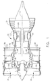
- FIG. 1 schematically shows an exemplary turbofan gas turbine engine 10. While turbofan engines in general are well known in the art, a brief description of the overall configuration of the engine 10 and the interrelationship of its various components will enhance understanding of the invention to be described below. Furthermore, it should be pointed out that a turbofan engine is used only as an example; the present invention is not limited to turbofan engines and can be implemented in a wide variety of engine types as well as other applications.
- the engine 10 includes, in serial axial flow communication about a longitudinal centerline axis 12, a fan 14, booster 16, high pressure compressor 18, combustor 20, high pressure turbine 22, and low pressure turbine 24.
- the high pressure turbine 22 is drivingly connected to the high pressure compressor 18 with a first rotor shaft 26, and the low pressure turbine 24 is drivingly connected to both the booster 16 and the fan 14 with a second rotor shaft 28.
- the fan 14 comprises a plurality of radially extending fan blades 30 mounted on an annular disk 32, wherein the disk 32 and the blades 30 are rotatable about the longitudinal centerline axis 12 of engine 10.
- ambient air 34 enters the engine inlet and a first portion of the ambient air 34, denoted the primary gas stream 36, passes through the fan 14, booster 16 and high pressure compressor 18, being pressurized by each component in succession.
- the primary gas stream 36 then enters the combustor 20 where the pressurized air is mixed with fuel and burned to provide a high energy stream of hot combustion gases.
- the high energy gas stream passes through the high pressure turbine 22 where it is expanded, with energy extracted to drive the high pressure compressor 18, and then the low pressure turbine 24 where it is further expanded, with energy being extracted to drive the fan 14 and the booster 16.
- a second portion of the ambient air 34 denoted the secondary or bypass airflow 38, passes through the fan 14 and the fan outlet guide vanes 40 before exiting the engine through an annular duct 42, wherein the secondary airflow 38 provides a significant portion of the engine thrust.
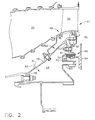
- the high pressure turbine 22 includes a turbine nozzle assembly 44 and a first stage turbine rotor (not shown in Figure 2) located aft or downstream of the turbine nozzle assembly 44.
- the turbine nozzle assembly 44 and the turbine rotor are spaced axially to define a forward wheel cavity 45 therebetween (i.e., immediately forward of the turbine rotor).
- the forward wheel cavity 45 is in fluid communication with the turbine flow path through which the hot combustion gases flow.
- the turbine nozzle assembly 44 includes an inner nozzle support 46 to which a plurality of circumferentially adjoining nozzle segments 48 is mounted.
- the nozzle segments 48 collectively form a complete 360° assembly.
- Each segment 48 has two or more circumferentially spaced vanes 50 (one shown in Figure 2) over which the combustion gases flow.
- the vanes 50 are configured so as to optimally direct the combustion gases to the first stage turbine rotor.
- the inner nozzle support 46 is a stationary member suitably supported in the engine 10 and has a substantially conical configuration.
- the nozzle segments 48 are mounted to the axially and radially distal end of the inner nozzle support 46.
- the turbine nozzle assembly 44 also includes a stationary member 52 fastened to an inwardly extending flange 53 formed on the inner nozzle support 46, near the axially and radially distal end thereof. Although shown as a separate piece, the stationary member 52 could alternatively be integrally formed with the inner nozzle support 46. The inner nozzle support 46 and the stationary member 52 define a chamber 54 located axially therebetween.
- the stationary member 52 is a generally annular structure having an outer flange 56, and inner flange 58 and an inducer 60 radially disposed between the outer flange 56 and the inner flange 58.
- the outer flange 56 is formed on a flange arm 61 that is annular in configuration and defines an axially extending, substantially cylindrical surface.
- cooling air typically air diverted from the compressor 18
- the inducer 60 accelerates and directs some of this air tangentially toward the turbine rotor located aft of the turbine nozzle assembly 44.
- the inducer 60 typically comprises a circumferentially disposed array of vanes that controls the tangential speed and direction of the airflow so that it is substantially equal to that of the turbine rotor.
- the engine 10 further includes an annular rotating member 64 fixed for rotation with the turbine rotor.
- the rotating member 64 contacts the stationary member 52 to form a forward outer seal 66 for sealing compressor discharge air bled off for cooling purposes from the hot gases in the turbine flow path.
- the forward outer seal 66 is a rotating labyrinth seal that includes a number of thin, tooth-like projections 68 attached to, or integrally formed on, the rotating member 64.
- the projections 68 are annular members that extend radially outward toward the flange arm 61.
- the labyrinth seal 66 further includes an annular stator element 70 attached to the flange arm 61 and positioned radially outward of and circumferentially about the projections 68.
- each one of the projections 68 is axially aligned with a corresponding tier of the stator element 70.
- axially aligned it is meant that each projection 68 is located along the axial direction between the forward and aft edges of the corresponding tier.
- the outer circumference of each projection 68 rotates within a small tolerance of the corresponding inner circumference of the stator element 70, thereby effecting sealing between the cooling air and the hot gases in the turbine flow path.
- the stator element 70 is preferably made of a honeycomb material to reduce friction and subsequent heat generation during operation.
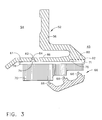
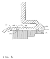
- bypass circuit 72 provides for the flow of air from the chamber 54 to the forward wheel cavity 45, thereby providing faster heating of the flange arm 61 and the outer flange 56 and reducing the thermal gradient thereof.
- the airflow through the bypass circuit 72 also purges the forward wheel cavity 45 so as to prevent hot gas ingestion.
- the bypass circuit 72 comprises first and second channels 74 and 76 formed in the radially inner surface 78 of the flange arm 61, which is the surface to which the backing plate 71 is mounted. Both of the first and second channels 74 and 76 extend around the entire circumference of the flange arm 61 to define continuous ring channels.
- the channels 74 and 76 are spaced axially with the first channel 74 being located near the forward end of the flange arm 61, and the second channel 76 being located near the aft end of the flange arm 61.
- the bypass circuit 72 further includes a plurality of connecting slots 80 formed in the radially inner surface 78 and equally spaced about the circumference of the flange arm 61.
- the connecting slots 80 extend axially between the first and second channels 74 and 76 to allow air to flow from the first channel 74 to the second channel 76.
- the bypass circuit 72 further includes a plurality of inlet passages 82 equally spaced about the circumference of the flange arm 61.
- Each inlet passage 82 extends radially through the flange arm 61 from an inlet port 84 formed on the radially outer surface 86 of the flange arm 61 to the first channel 74.
- the inlet passages 82 thus provide fluid communication between the chamber 54 and the first channel 74.
- the inlet passages could alternatively have a non-radial orientation as long as they provided fluid communication between the chamber 54 and the first channel 74.
- the number and size of the inlet passages 82 are selected to provide a significant contribution to control the desired amount of airflow through the bypass circuit 72.
- a plurality of outlet slots 88 is formed in the radially inner surface 78 and equally spaced about the circumference of the flange arm 61.
- Each outlet slot 88 extends axially from the second channel 76 to the aft end of the flange arm 61 to define an outlet port 90 in the aft facing edge 92 of the flange arm 61.
- the outlet slots 88 are thus in fluid communication with the first channel 74 via the second channel 76 and the connecting slots 80. Although they can be substantially parallel to the centerline axis 12, the outlet slots 88, as well as the connecting slots 80, are preferably angled in a circumferential direction to minimize flow-turning losses and pre-swirl the cavity purge air to reduce cavity windage and absolute air temperature.
- the present invention is not limited to two ring channels. Additional ring channels, and corresponding additional sets of connecting slots, could be utilized.
- the bypass circuit could be configured with a single ring channel. In this case, a plurality of inlet passages would be formed in the flange arm in fluid communication with the single ring channel. A plurality of outlet slots would be formed in the flange arm so as to extend from the single ring channel to the aft end of the flange arm. Connecting slots would not be required in this embodiment.
- the configuration of the bypass circuit simplifies machining relative to conventional bypass circuits.
- the two circumferential channels 74 and 76 can be turned on a lathe, and the angled connecting slots 80 and outlet slots 88 can be milled with a ball mill. This provides a large fillet radius that minimizes stress concentrations in the flange arm 61.
- the connecting slots 80 and outlet slots 88 define fillet radii that are greater than the slot depth. In one embodiment, slot fillet radii are approximately 3-4 times greater than the slot depth.
- bypass circuit 72 During engine operation, air from the chamber 54 enters the bypass circuit 72 via the inlet ports 84. The air passes through the inlet passages 82 to the first channel 74. Air then passes from the first channel 74 to the second channel 76 via the connecting slots 80. From the second channel 76, the air flows through the outlet slots 88 and exits the bypass circuit 72 through the outlet ports 90 into the forward wheel cavity 45.
- the geometry of the bypass circuit 72 provides a more uniform distribution of the relatively hot air to heat the flange arm 61 and the outer flange 56 evenly.
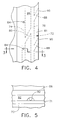
- the bypass circuit 172 comprises first and second channels 174 and 176 formed in the radially outer surface 179 of the backing plate 171, which is the surface that is mounted to the flange arm 161. Both of the first and second channels 174 and 176 extend around the entire circumference of the backing plate 171 to define continuous ring channels.
- the channels 174 and 176 are spaced axially with the first channel 174 being located near the forward end of the backing plate 171, and the second channel 176 being located near the aft end of the backing plate 171.
- the bypass circuit 172 further includes a plurality of connecting slots 180 formed in the radially outer surface 179 and equally spaced about the circumference of the backing plate 171.
- the connecting slots 180 extend axially between the first and second channels 174 and 176 to allow air to flow from the first channel 174 to the second channel 176.
- the bypass circuit 172 further includes a plurality of inlet passages 182 equally spaced about the circumference of the flange arm 161. Each inlet passage 182 extends radially through the flange arm 161 from an inlet port 184 formed on the radially outer surface 186 of the flange arm 161 to the first channel 174.
- a plurality of outlet slots 188 is formed in the radially outer surface 179 and equally spaced about the circumference of the backing plate 171. Each outlet slot 188 extends axially from the second channel 176 to the aft end of the backing plate 171 to define an outlet port 190 in the aft facing edge of the backing plate 171.
- the outlet slots 188 are thus in fluid communication with the first channel 174 via the second channel 176 and the connecting slots 180.
- this embodiment is not limited to two ring channels. Additional ring channels, and corresponding additional sets of connecting slots, could be utilized.
- the bypass circuit could be configured with just a single ring channel.
Landscapes
- Engineering & Computer Science (AREA)
- Mechanical Engineering (AREA)
- General Engineering & Computer Science (AREA)
- Turbine Rotor Nozzle Sealing (AREA)
- Structures Of Non-Positive Displacement Pumps (AREA)
Applications Claiming Priority (2)
| Application Number | Priority Date | Filing Date | Title |
|---|---|---|---|
| US757188 | 2001-01-09 | ||
| US10/757,188 US7025565B2 (en) | 2004-01-14 | 2004-01-14 | Gas turbine engine component having bypass circuit |
Publications (4)
| Publication Number | Publication Date |
|---|---|
| EP1555393A2 true EP1555393A2 (de) | 2005-07-20 |
| EP1555393A3 EP1555393A3 (de) | 2013-01-30 |
| EP1555393B1 EP1555393B1 (de) | 2017-07-19 |
| EP1555393B2 EP1555393B2 (de) | 2020-09-23 |
Family
ID=34620680
Family Applications (1)
| Application Number | Title | Priority Date | Filing Date |
|---|---|---|---|
| EP05250168.1A Expired - Lifetime EP1555393B2 (de) | 2004-01-14 | 2005-01-14 | Gasturbinenmotorkomponenten mit einem Umgehungskreislauf |
Country Status (4)
| Country | Link |
|---|---|
| US (2) | US7025565B2 (de) |
| EP (1) | EP1555393B2 (de) |
| JP (1) | JP4746325B2 (de) |
| CN (1) | CN100543283C (de) |
Cited By (3)
| Publication number | Priority date | Publication date | Assignee | Title |
|---|---|---|---|---|
| EP2615253A1 (de) * | 2012-01-09 | 2013-07-17 | General Electric Company | Turbinenschaufeldichtungsträger mit Schlitzen für Kühlung und Montage |
| US9062561B2 (en) | 2010-09-29 | 2015-06-23 | Rolls-Royce Plc | Endwall component for a turbine stage of a gas turbine engine |
| EP3047130B1 (de) * | 2013-09-18 | 2020-01-15 | United Technologies Corporation | Gas turbinen dichtungsanordnung welche wabendichtungen mit keilprofil beinhaltet |
Families Citing this family (25)
| Publication number | Priority date | Publication date | Assignee | Title |
|---|---|---|---|---|
| US7341429B2 (en) * | 2005-11-16 | 2008-03-11 | General Electric Company | Methods and apparatuses for cooling gas turbine engine rotor assemblies |
| ITMI20061086A1 (it) * | 2006-06-01 | 2007-12-02 | Nuovo Pignone Spa | Dispositivo per ottimizzare il raffreddamento nelle turbine a gas |
| US8167547B2 (en) * | 2007-03-05 | 2012-05-01 | United Technologies Corporation | Gas turbine engine with canted pocket and canted knife edge seal |
| JP2010190057A (ja) * | 2009-02-16 | 2010-09-02 | Ihi Corp | タービンの設計方法及びタービン |
| US9816441B2 (en) * | 2009-03-30 | 2017-11-14 | United Technologies Corporation | Gas turbine engine with stacked accessory components |
| US8887486B2 (en) * | 2011-10-24 | 2014-11-18 | Hamilton Sundstrand Corporation | Ram air fan inlet housing |
| US9194259B2 (en) * | 2012-05-31 | 2015-11-24 | General Electric Company | Apparatus for minimizing solid particle erosion in steam turbines |
| US9850780B2 (en) | 2012-12-29 | 2017-12-26 | United Technologies Corporation | Plate for directing flow and film cooling of components |
| US9206742B2 (en) * | 2012-12-29 | 2015-12-08 | United Technologies Corporation | Passages to facilitate a secondary flow between components |
| US10704468B2 (en) | 2013-02-28 | 2020-07-07 | Raytheon Technologies Corporation | Method and apparatus for handling pre-diffuser airflow for cooling high pressure turbine components |
| JP6353056B2 (ja) * | 2013-09-06 | 2018-07-04 | ゼネラル・エレクトリック・カンパニイ | 第1のハニカム層および第2のハニカム層ならびにこれらの間の穿孔された中間シールプレートを備えるガスタービン用積層シールアセンブリ |
| CA2932601C (en) | 2015-06-17 | 2023-10-03 | Rolls-Royce Corporation | Labyrinth seal with tunable flow splitter |
| US10329938B2 (en) * | 2017-05-31 | 2019-06-25 | General Electric Company | Aspirating face seal starter tooth abradable pocket |
| US11149692B2 (en) | 2018-06-12 | 2021-10-19 | General Electric Company | Deflection mitigation structure for combustion system |
| DE102018210513A1 (de) * | 2018-06-27 | 2020-01-02 | MTU Aero Engines AG | Rotor für eine Strömungsmaschine und Strömungsmaschine mit einem solchen Rotor |
| US11293375B2 (en) | 2020-02-12 | 2022-04-05 | General Electric Company | Variable area ejector |
| US11674396B2 (en) | 2021-07-30 | 2023-06-13 | General Electric Company | Cooling air delivery assembly |
| US11674405B2 (en) | 2021-08-30 | 2023-06-13 | General Electric Company | Abradable insert with lattice structure |
| US20230265862A1 (en) | 2022-02-21 | 2023-08-24 | General Electric Company | Turbofan engine having angled inlet pre-swirl vanes |
| US11725526B1 (en) | 2022-03-08 | 2023-08-15 | General Electric Company | Turbofan engine having nacelle with non-annular inlet |
| US12385430B2 (en) | 2023-11-30 | 2025-08-12 | General Electric Company | Gas turbine engine with forward swept outlet guide vanes |
| US12209557B1 (en) | 2023-11-30 | 2025-01-28 | General Electric Company | Gas turbine engine with forward swept outlet guide vanes |
| US12228037B1 (en) | 2023-12-04 | 2025-02-18 | General Electric Company | Guide vane assembly with fixed and variable pitch inlet guide vanes |
| US12313021B1 (en) | 2024-03-14 | 2025-05-27 | General Electric Company | Outer nacelle with inlet guide vanes and acoustic treatment |
| US12331646B1 (en) * | 2024-05-13 | 2025-06-17 | Rtx Corporation | Air seal for a turbine engine |
Citations (2)
| Publication number | Priority date | Publication date | Assignee | Title |
|---|---|---|---|---|
| US4320903A (en) | 1978-09-27 | 1982-03-23 | Societe Nationale D'etude Et De Construction De Moteurs D'aviation | Labyrinth seals |
| US4513975A (en) | 1984-04-27 | 1985-04-30 | General Electric Company | Thermally responsive labyrinth seal |
Family Cites Families (15)
| Publication number | Priority date | Publication date | Assignee | Title |
|---|---|---|---|---|
| US2648520A (en) * | 1949-08-02 | 1953-08-11 | Heinz E Schmitt | Air-cooled turbine blade |
| US4157232A (en) * | 1977-10-31 | 1979-06-05 | General Electric Company | Turbine shroud support |
| US4280792A (en) | 1979-02-09 | 1981-07-28 | Avco Corporation | Air-cooled turbine rotor shroud with restraints |
| US4397471A (en) * | 1981-09-02 | 1983-08-09 | General Electric Company | Rotary pressure seal structure and method for reducing thermal stresses therein |
| FR2574473B1 (fr) | 1984-11-22 | 1987-03-20 | Snecma | Anneau de turbine pour une turbomachine a gaz |
| FR2624953B1 (fr) | 1987-12-16 | 1990-04-20 | Snecma | Chambre de combustion, pour turbomachines, possedant un convergent a doubles parois |
| US5984630A (en) * | 1997-12-24 | 1999-11-16 | General Electric Company | Reduced windage high pressure turbine forward outer seal |
| US6050079A (en) * | 1997-12-24 | 2000-04-18 | General Electric Company | Modulated turbine cooling system |
| EP1033476B1 (de) * | 1999-03-03 | 2006-09-13 | General Electric Company | Wärmeaustausch Kreislauf für einen Turbinenrotor |
| US6471216B1 (en) * | 1999-05-24 | 2002-10-29 | General Electric Company | Rotating seal |
| JP2001197924A (ja) * | 2000-01-18 | 2001-07-24 | Soung An Jae | 文様人造爪およびその製造方法 |
| US6485025B1 (en) * | 2000-11-27 | 2002-11-26 | Neomet Limited | Metallic cellular structure |
| JP2002172018A (ja) * | 2001-09-07 | 2002-06-18 | General Kk | 付け爪製造装置 |
| JP2004344628A (ja) * | 2003-05-23 | 2004-12-09 | Masaru Tsukamoto | コンピューター化した付け爪用デザインの製作方法及びこれを用いた付け爪 |
| JP2004303249A (ja) * | 2004-03-30 | 2004-10-28 | Kenji Sato | 包装材印刷システム、広告料金課金装置、包装材印刷方法、サーバ装置、クライアント装置、プリンタ、被印刷材、店舗、コンピュータプログラム、記録媒体 |
-
2004
- 2004-01-14 US US10/757,188 patent/US7025565B2/en not_active Expired - Lifetime
-
2005
- 2005-01-13 JP JP2005006070A patent/JP4746325B2/ja not_active Expired - Fee Related
- 2005-01-14 CN CNB2005100043385A patent/CN100543283C/zh not_active Expired - Lifetime
- 2005-01-14 EP EP05250168.1A patent/EP1555393B2/de not_active Expired - Lifetime
-
2006
- 2006-04-05 US US11/278,701 patent/US7210900B2/en not_active Expired - Lifetime
Patent Citations (2)
| Publication number | Priority date | Publication date | Assignee | Title |
|---|---|---|---|---|
| US4320903A (en) | 1978-09-27 | 1982-03-23 | Societe Nationale D'etude Et De Construction De Moteurs D'aviation | Labyrinth seals |
| US4513975A (en) | 1984-04-27 | 1985-04-30 | General Electric Company | Thermally responsive labyrinth seal |
Cited By (5)
| Publication number | Priority date | Publication date | Assignee | Title |
|---|---|---|---|---|
| US9062561B2 (en) | 2010-09-29 | 2015-06-23 | Rolls-Royce Plc | Endwall component for a turbine stage of a gas turbine engine |
| EP2615253A1 (de) * | 2012-01-09 | 2013-07-17 | General Electric Company | Turbinenschaufeldichtungsträger mit Schlitzen für Kühlung und Montage |
| US9011078B2 (en) | 2012-01-09 | 2015-04-21 | General Electric Company | Turbine vane seal carrier with slots for cooling and assembly |
| RU2618805C2 (ru) * | 2012-01-09 | 2017-05-11 | Дженерал Электрик Компани | Держатель уплотнения и сопловая лопатка для газовой турбины (варианты) |
| EP3047130B1 (de) * | 2013-09-18 | 2020-01-15 | United Technologies Corporation | Gas turbinen dichtungsanordnung welche wabendichtungen mit keilprofil beinhaltet |
Also Published As
| Publication number | Publication date |
|---|---|
| JP2005201275A (ja) | 2005-07-28 |
| CN1670349A (zh) | 2005-09-21 |
| EP1555393A3 (de) | 2013-01-30 |
| US20060162339A1 (en) | 2006-07-27 |
| CN100543283C (zh) | 2009-09-23 |
| US7025565B2 (en) | 2006-04-11 |
| EP1555393B1 (de) | 2017-07-19 |
| EP1555393B2 (de) | 2020-09-23 |
| US7210900B2 (en) | 2007-05-01 |
| US20050150234A1 (en) | 2005-07-14 |
| JP4746325B2 (ja) | 2011-08-10 |
Similar Documents
| Publication | Publication Date | Title |
|---|---|---|
| US7025565B2 (en) | Gas turbine engine component having bypass circuit | |
| EP1205636B1 (de) | Turbinenschaufel einer Gasturbine sowie Verfahren zur Kühlung der Schaufel | |
| EP0608142B1 (de) | Kühlsystem für eine Gasturbine | |
| EP2075437B1 (de) | System zur Kühlung einer Gasturbine aus mehreren Quellen | |
| EP1167722B1 (de) | Verfahren zur Kühlung einer Gasturbine sowie Gasturbine | |
| EP1921255B1 (de) | Turbinenmotor mit Zwischenkühlung | |
| JP4492951B2 (ja) | 三重回路タービン冷却 | |
| CA2609279C (en) | Compound clearance control engine | |
| US6331097B1 (en) | Method and apparatus for purging turbine wheel cavities | |
| CN114718656B (zh) | 用于控制燃气涡轮发动机内的叶片间隙的系统 | |
| GB2270118A (en) | System for cooling a turbomachine compressor and for controlling clearances therein. | |
| EP2855884A1 (de) | Kühlmittelversorgungssystem für hochdruckturbine | |
| US20190203600A1 (en) | Compressor Cooling in a Gas Turbine Engine | |
| CA2956362A1 (en) | Gas turbine engine with a rim seal between the rotor and stator | |
| JP2017110652A (ja) | 活性高圧圧縮機クリアランス制御 | |
| EP1057976B1 (de) | Rotierende Dichtung | |
| US10934845B2 (en) | Dual cooling airflow to blades | |
| GB2057573A (en) | Turbine rotor assembly | |
| US20240352942A1 (en) | Tandem blade rotor disk | |
| EP3647542A1 (de) | Zwischengekühlter tangentialer luftinjektor für gasturbinentriebwerke |
Legal Events
| Date | Code | Title | Description |
|---|---|---|---|
| PUAI | Public reference made under article 153(3) epc to a published international application that has entered the european phase |
Free format text: ORIGINAL CODE: 0009012 |
|
| AK | Designated contracting states |
Kind code of ref document: A2 Designated state(s): AT BE BG CH CY CZ DE DK EE ES FI FR GB GR HU IE IS IT LI LT LU MC NL PL PT RO SE SI SK TR |
|
| AX | Request for extension of the european patent |
Extension state: AL BA HR LV MK YU |
|
| PUAL | Search report despatched |
Free format text: ORIGINAL CODE: 0009013 |
|
| AK | Designated contracting states |
Kind code of ref document: A3 Designated state(s): AT BE BG CH CY CZ DE DK EE ES FI FR GB GR HU IE IS IT LI LT LU MC NL PL PT RO SE SI SK TR |
|
| AX | Request for extension of the european patent |
Extension state: AL BA HR LV MK YU |
|
| RIC1 | Information provided on ipc code assigned before grant |
Ipc: F01D 25/12 20060101ALI20121221BHEP Ipc: F01D 11/02 20060101ALI20121221BHEP Ipc: F01D 11/00 20060101AFI20121221BHEP Ipc: F01D 25/10 20060101ALI20121221BHEP Ipc: F01D 11/12 20060101ALI20121221BHEP |
|
| 17P | Request for examination filed |
Effective date: 20130730 |
|
| RBV | Designated contracting states (corrected) |
Designated state(s): AT BE BG CH CY CZ DE DK EE ES FI FR GB GR HU IE IS IT LI LT LU MC NL PL PT RO SE SI SK TR |
|
| AKX | Designation fees paid |
Designated state(s): DE FR GB |
|
| 17Q | First examination report despatched |
Effective date: 20131115 |
|
| GRAP | Despatch of communication of intention to grant a patent |
Free format text: ORIGINAL CODE: EPIDOSNIGR1 |
|
| STAA | Information on the status of an ep patent application or granted ep patent |
Free format text: STATUS: GRANT OF PATENT IS INTENDED |
|
| INTG | Intention to grant announced |
Effective date: 20170223 |
|
| GRAS | Grant fee paid |
Free format text: ORIGINAL CODE: EPIDOSNIGR3 |
|
| GRAA | (expected) grant |
Free format text: ORIGINAL CODE: 0009210 |
|
| STAA | Information on the status of an ep patent application or granted ep patent |
Free format text: STATUS: THE PATENT HAS BEEN GRANTED |
|
| AK | Designated contracting states |
Kind code of ref document: B1 Designated state(s): DE FR GB |
|
| REG | Reference to a national code |
Ref country code: GB Ref legal event code: FG4D |
|
| REG | Reference to a national code |
Ref country code: DE Ref legal event code: R096 Ref document number: 602005052347 Country of ref document: DE |
|
| REG | Reference to a national code |
Ref country code: DE Ref legal event code: R026 Ref document number: 602005052347 Country of ref document: DE |
|
| PLAF | Information modified related to communication of a notice of opposition and request to file observations + time limit |
Free format text: ORIGINAL CODE: EPIDOSCOBS2 |
|
| PLBI | Opposition filed |
Free format text: ORIGINAL CODE: 0009260 |
|
| PLAX | Notice of opposition and request to file observation + time limit sent |
Free format text: ORIGINAL CODE: EPIDOSNOBS2 |
|
| 26 | Opposition filed |
Opponent name: UNITED TECHNOLOGIES CORPORATION Effective date: 20180419 |
|
| REG | Reference to a national code |
Ref country code: DE Ref legal event code: R119 Ref document number: 602005052347 Country of ref document: DE |
|
| PLBB | Reply of patent proprietor to notice(s) of opposition received |
Free format text: ORIGINAL CODE: EPIDOSNOBS3 |
|
| GBPC | Gb: european patent ceased through non-payment of renewal fee |
Effective date: 20180114 |
|
| REG | Reference to a national code |
Ref country code: DE Ref legal event code: R073 Ref document number: 602005052347 Country of ref document: DE |
|
| PG25 | Lapsed in a contracting state [announced via postgrant information from national office to epo] |
Ref country code: FR Free format text: LAPSE BECAUSE OF NON-PAYMENT OF DUE FEES Effective date: 20180131 Ref country code: DE Free format text: LAPSE BECAUSE OF NON-PAYMENT OF DUE FEES Effective date: 20180801 |
|
| REG | Reference to a national code |
Ref country code: FR Ref legal event code: ST Effective date: 20180928 |
|
| REG | Reference to a national code |
Ref country code: GB Ref legal event code: S28 Free format text: APPLICATION FILED |
|
| REG | Reference to a national code |
Ref country code: DE Ref legal event code: R074 Ref document number: 602005052347 Country of ref document: DE |
|
| REG | Reference to a national code |
Ref country code: DE Ref legal event code: R074 Ref document number: 602005052347 Country of ref document: DE |
|
| PG25 | Lapsed in a contracting state [announced via postgrant information from national office to epo] |
Ref country code: GB Free format text: LAPSE BECAUSE OF NON-PAYMENT OF DUE FEES Effective date: 20180114 |
|
| REG | Reference to a national code |
Ref country code: FR Ref legal event code: RN Effective date: 20181025 |
|
| REG | Reference to a national code |
Ref country code: GB Ref legal event code: S28 Free format text: RESTORATION ALLOWED Effective date: 20190109 |
|
| PG25 | Lapsed in a contracting state [announced via postgrant information from national office to epo] |
Ref country code: DE Free format text: LAPSE BECAUSE OF NON-PAYMENT OF DUE FEES Effective date: 20180801 |
|
| PGRI | Patent reinstated in contracting state [announced from national office to epo] |
Ref country code: DE Effective date: 20181115 |
|
| PG25 | Lapsed in a contracting state [announced via postgrant information from national office to epo] |
Ref country code: FR Free format text: LAPSE BECAUSE OF NON-PAYMENT OF DUE FEES Effective date: 20180131 |
|
| PGRI | Patent reinstated in contracting state [announced from national office to epo] |
Ref country code: FR Effective date: 20181204 |
|
| APAH | Appeal reference modified |
Free format text: ORIGINAL CODE: EPIDOSCREFNO |
|
| APAW | Appeal reference deleted |
Free format text: ORIGINAL CODE: EPIDOSDREFNO |
|
| APAY | Date of receipt of notice of appeal deleted |
Free format text: ORIGINAL CODE: EPIDOSDNOA2O |
|
| APBM | Appeal reference recorded |
Free format text: ORIGINAL CODE: EPIDOSNREFNO |
|
| APBP | Date of receipt of notice of appeal recorded |
Free format text: ORIGINAL CODE: EPIDOSNNOA2O |
|
| APBU | Appeal procedure closed |
Free format text: ORIGINAL CODE: EPIDOSNNOA9O |
|
| PUAH | Patent maintained in amended form |
Free format text: ORIGINAL CODE: 0009272 |
|
| STAA | Information on the status of an ep patent application or granted ep patent |
Free format text: STATUS: PATENT MAINTAINED AS AMENDED |
|
| 27A | Patent maintained in amended form |
Effective date: 20200923 |
|
| AK | Designated contracting states |
Kind code of ref document: B2 Designated state(s): DE FR GB |
|
| REG | Reference to a national code |
Ref country code: DE Ref legal event code: R102 Ref document number: 602005052347 Country of ref document: DE |
|
| REG | Reference to a national code |
Ref country code: DE Ref legal event code: R082 Ref document number: 602005052347 Country of ref document: DE Representative=s name: HOFFMANN EITLE PATENT- UND RECHTSANWAELTE PART, DE Ref country code: DE Ref legal event code: R082 Ref document number: 602005052347 Country of ref document: DE Representative=s name: HOFFMANN - EITLE PATENT- UND RECHTSANWAELTE PA, DE |
|
| P01 | Opt-out of the competence of the unified patent court (upc) registered |
Effective date: 20230414 |
|
| PGFP | Annual fee paid to national office [announced via postgrant information from national office to epo] |
Ref country code: GB Payment date: 20231219 Year of fee payment: 20 |
|
| PGFP | Annual fee paid to national office [announced via postgrant information from national office to epo] |
Ref country code: FR Payment date: 20231219 Year of fee payment: 20 |
|
| PGFP | Annual fee paid to national office [announced via postgrant information from national office to epo] |
Ref country code: DE Payment date: 20231219 Year of fee payment: 20 |
|
| REG | Reference to a national code |
Ref country code: DE Ref legal event code: R071 Ref document number: 602005052347 Country of ref document: DE |
|
| REG | Reference to a national code |
Ref country code: GB Ref legal event code: PE20 Expiry date: 20250113 |
|
| PG25 | Lapsed in a contracting state [announced via postgrant information from national office to epo] |
Ref country code: GB Free format text: LAPSE BECAUSE OF EXPIRATION OF PROTECTION Effective date: 20250113 |