EP1555147A1 - Air conditioning device for a vehicle - Google Patents
Air conditioning device for a vehicle Download PDFInfo
- Publication number
- EP1555147A1 EP1555147A1 EP04290087A EP04290087A EP1555147A1 EP 1555147 A1 EP1555147 A1 EP 1555147A1 EP 04290087 A EP04290087 A EP 04290087A EP 04290087 A EP04290087 A EP 04290087A EP 1555147 A1 EP1555147 A1 EP 1555147A1
- Authority
- EP
- European Patent Office
- Prior art keywords
- air
- air conditioning
- conditioning device
- outflow openings
- vehicle interior
- Prior art date
- Legal status (The legal status is an assumption and is not a legal conclusion. Google has not performed a legal analysis and makes no representation as to the accuracy of the status listed.)
- Granted
Links
Images


Classifications
-
- B—PERFORMING OPERATIONS; TRANSPORTING
- B60—VEHICLES IN GENERAL
- B60H—ARRANGEMENTS OF HEATING, COOLING, VENTILATING OR OTHER AIR-TREATING DEVICES SPECIALLY ADAPTED FOR PASSENGER OR GOODS SPACES OF VEHICLES
- B60H1/00—Heating, cooling or ventilating [HVAC] devices
- B60H1/00007—Combined heating, ventilating, or cooling devices
- B60H1/00021—Air flow details of HVAC devices
- B60H1/00064—Air flow details of HVAC devices for sending air streams of different temperatures into the passenger compartment
-
- B—PERFORMING OPERATIONS; TRANSPORTING
- B60—VEHICLES IN GENERAL
- B60H—ARRANGEMENTS OF HEATING, COOLING, VENTILATING OR OTHER AIR-TREATING DEVICES SPECIALLY ADAPTED FOR PASSENGER OR GOODS SPACES OF VEHICLES
- B60H1/00—Heating, cooling or ventilating [HVAC] devices
- B60H1/00007—Combined heating, ventilating, or cooling devices
- B60H1/00021—Air flow details of HVAC devices
- B60H2001/00114—Heating or cooling details
- B60H2001/00128—Electric heaters
-
- B—PERFORMING OPERATIONS; TRANSPORTING
- B60—VEHICLES IN GENERAL
- B60H—ARRANGEMENTS OF HEATING, COOLING, VENTILATING OR OTHER AIR-TREATING DEVICES SPECIALLY ADAPTED FOR PASSENGER OR GOODS SPACES OF VEHICLES
- B60H1/00—Heating, cooling or ventilating [HVAC] devices
- B60H1/00007—Combined heating, ventilating, or cooling devices
- B60H1/00021—Air flow details of HVAC devices
- B60H2001/00185—Distribution of conditionned air
- B60H2001/002—Distribution of conditionned air to front and rear part of passenger compartment
Definitions
- the present invention relates to an air conditioning device for a motor vehicle having the features of the preamble of the claim 1.
- the invention further relates to an air distributor for a Air conditioning device according to claim 9.
- An air conditioning system of a motor vehicle usually has several in the vehicle interior opening outflow openings, the optionally supplied with cooled or heated air can.
- at least two outflow openings each in the footwell, in the area of a center console and above a dashboard provided, at least one on each Driver and a passenger side.
- To distribute the air-conditioned Air on the various outflow openings is this in known Air conditioning systems each assigned at least one adjusting device, by means of which a passage opening is variably opened or can be closed.
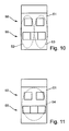
- Figures 10 and 11 illustrate in schematic representations known arrangements of vehicle air conditioning systems, in which a Row of outflow openings (not shown) in a front Area 50 of a vehicle interior 51, for example. In the area of a Dashboard, arranged by the conditioned air in the Vehicle interior 51 can be promoted.
- Figure 10 illustrates an arrangement in which the temperature for a left-hand climate zone 52 and for a right climate zone 53 separately adjustable are, while in the arrangement of Figure 11, the entire Vehicle interior 51 forms a common climate zone 54. Both shown arrangements is common that the front area 50 each can be conditioned in the desired manner, while the rear area 55 may be due to lack of outflow openings not adequately with conditioned air can be supplied.
- the present invention is based on the object, a vehicle air conditioning for indoor temperature control or air conditioning to provide sufficient air conditioning of ayedfond Schemes allows.
- an air conditioning device in a region of an air duct at least one branch channel is arranged near a mixing flap is through which conditioned air into a rear area the vehicle interior is conductive.
- the inventive Air conditioning device enables sufficient air conditioning the Anlagenfond Schemes at the same time very compact Construction of the air distribution facilities. There are no additional ones Mixing flaps, adjusting motors, adjusting mechanisms o. Like. Necessary, as is the case with known air conditioners.
- the Air outlet for the at least one branch channel is preferably so placed so that it rests within the mixing zone. hereby The rear seats can be supplied with cold, warm or tempered air become.
- the air distribution in the front area of the vehicle interior can done in a known manner. So can the air distribution between at least two outflow openings opening into the motor vehicle interior by means of at least one distribution or mixing flap is variably adjustable.
- flaps By means of one or more such flaps can with only one Component a variable air distribution between two or more outflow openings be achieved.
- First outflow openings can For example, lead into a footwell of the vehicle interior, while second outflow openings in an upper region of the Automotive interior can open.
- the air conditioning system Optionally, a separate regulation for a right and a Provide left interior zone, while the rear area typically has no separate control for left and right side. Possibly.
- Further flaps can be provided by means of which the in the fund area opening outflow openings variably closed could be.
- the outflow openings for the rear area can be in the B-pillars and / or arranged in the C-pillars.
- Optional or additional can have one or more outflow openings in the floor area be provided near a center tunnel.
- Several outflow openings at different heights can allow stratification of the air so that lower outflow preferably for introduction of hot air and upper outlets for introduction of cold air can serve.
- the branch channel and / or the outflow openings by means of flaps o.
- flaps Like. Are variably openable or closable.
- An air distributor of an air conditioning device comprises a housing with a blower disposed therein, a cooling device, a heating device and at least one branch channel in one area the air duct located near the mixing flap is.
- the inventive Air distributor is simple and very compact and needed Less mobile compared to known devices Actuators.
- FIGS 1 and 2 illustrate in principle representations of the Structure and the basic function of an inventive Air conditioning device 10.
- a housing 11 comprises an air duct 12 and has a blower 13 for generating a Air flow through the air duct 12 on.
- a cooling device 14 is arranged, a filter 16 can be connected upstream.
- the cooling device 14 is usually a so-called. Evaporator or a heat exchanger device and serves to cool the funded by the fan 13 Air flow 15.
- Downstream of the cooling device 14 is located a heater 18 disposed in a lower sub-channel 20 is.
- Parallel to this sub-channel 20 extends an additional bypass channel 21, the channel cross-section regulated by means of a mixing flap 22 and the means of the mixing flap 22 also completely closed can be.
- the mixing flap 22 serves for regulation the air temperature, since with closed flap 22 the entire conveyed air through the sub-channel 20 and the heater 18 flows, while the mixing flap open 22, the air due the lower resistance to the heater 18 over flows through the bypass passage 21.
- the air duct 12 opens after the branch again in a single channel and leads in shown embodiment to three outflow openings 24, 26, 28, each in a motor vehicle interior (not shown) lead.
- the first outflow opening 24 is directed downwards and serves usually for air conditioning or heating a footwell of the vehicle interior.
- the second outflow opening 26 may, for example, in a dashboard are located and used for air conditioning or heating of a middle area of the vehicle interior while the upward directed third outflow opening 28 primarily for heating or ventilation of a windshield and / or side windows the vehicle is used, for example, to keep them fog-free.
- the third outflow opening 28 also has a defroster function on.
- an air conditioning device 10 for Air conditioning of a vehicle interior that shown in Figure 1 Outflow openings 24, 26 and 28 in pairs for each side of the Vehicle interior available.
- the heater 18 may be a series of electrically heated Have wires that flows through the air to be heated become.
- a PTC element 30 be provided, in the illustrated embodiment, the heater is downstream and that for faster warming up can serve a desired temperature.
- the two distribution flaps 32 and 34 are arranged so close to each other, that is an overlap of their swivel ranges results.
- the two distribution flaps 32 and 34 must be made of this Reason so coupled in their pivotal movements, that they do not collide with each other.
- In this corner area is a pivot axis 38 of second distribution flap 34, depending on their position, the second outflow opening 26 or close the third outflow opening 28 can.
- FIG. 2 The schematic sectional view of Figure 2 illustrates the arrangement a branch channel 40 according to the invention, which is in one area the air duct 12 near the mixing flap 22 is arranged is and by what conditioned air in a rear Area of the vehicle interior is conductive.
- the Branch channels 40 are placed so that they are directly from the blend damper 22 tempered. Depending on their position flows then cooled or heated air in the vehicle fund.
- FIGS. 3 to 5 there are numerous positions the mixing flap 22 possible, so that the different desired air conditioning and heating conditions in the vehicle.
- FIG. 3 shows a middle position the blend flap 22, in which the rear seats and the front Area of the vehicle interior with tempered air applied become.
- FIG. 4 shows a stop position of the mixing flap 22, in which the sub-channel 20 with the heating device arranged therein 18 closed and only the bypass channel 21 is open, so that the fund is supplied with cooled air.
- FIG. 5 shows a further stop position of the mixing flap 22, in which the Partial channel 20 opened with the heating device 18 disposed therein and the bypass channel 21 is closed, so that the rear with heated Air is applied.
- FIG 6 illustrates a schematic representation of a vehicle interior 51, in which an air conditioning of a front area 50 and a rear area 55 by means of an air conditioning device 10 according to the embodiment described above is possible.
- the air-conditioned Air for the rear climate zone 57 is in the illustrated embodiment to lateral outflow openings in the area of the B-pillars the vehicle body promoted (see Figure 8).
- FIG 7 illustrates a schematic representation of a vehicle interior 51, each with a separate air conditioning of a left front area, a right front area and the Rear area 55 is possible.
- the conditioned air for the rear climate zone 57 is arranged too centrally in the embodiment shown Outflow openings in the region of a center tunnel of the vehicle body promoted (see Figure 9).
- Figures 8 and 9 illustrate in schematic representations possible embodiments of outflow openings for the rear climatic zone 57.
- the arrangement of Figure 8 provides outflow openings 60 and 61 in front of the B-pillar of the vehicle body, which are each arranged at different heights.
- the higher arranged upper outflow opening 60 may preferably serve for the supply of colder air into the rear climate zone 57, while the lower arranged lower outflow opening 61 is preferably used for hot air supply.
- the arrangement according to FIG. 9 has mean outflow openings 62 on, for example, in the area of a center tunnel 63 of the vehicle body let accommodate. Again, you can choose one, two or more outflow openings 62 for the rear climate zone 57th be provided, possibly also at different heights.
- All shown variants of the air conditioning device 10 have a very compact case design and allow the Air distribution to multiple outlets through fewer air distribution flaps or even just a flap in the desired manner to control.
- the branch channels 40 can be closed or reduce in their cross section, so that the air conditioning of the Fund area can be controlled as needed.
Abstract
Description
Die vorliegende Erfindung betrifft eine Klimatisierungsvorrichtung für
ein Kraftfahrzeug mit den Merkmalen des Oberbegriffs des Anspruchs
1. Die Erfindung betrifft weiterhin einen Luftverteiler für eine
Klimatisierungsvorrichtung gemäß Anspruch 9.The present invention relates to an air conditioning device for
a motor vehicle having the features of the preamble of the
Eine Klimaanlage eines Kraftfahrzeuges weist üblicherweise mehrere in den Fahrzeuginnenraum mündende Ausströmöffnungen auf, die wahlweise mit gekühlter oder erwärmter Luft beaufschlagt werden können. Typischerweise sind wenigstens jeweils zwei Ausströmöffnungen im Fußraum, im Bereich einer Mittelkonsole sowie oberhalb einer Armaturentafel vorgesehen, jeweils mindestens eine auf einer Fahrer- sowie einer Beifahrerseite. Zur Verteilung der klimatisierten Luft auf die verschiedenen Ausströmöffnungen ist diesen bei bekannten Klimaanlagen jeweils wenigstens eine Stelleinrichtung zugeordnet, mittels derer eine Durchlassöffnung variabel geöffnet oder verschlossen werden kann. An air conditioning system of a motor vehicle usually has several in the vehicle interior opening outflow openings, the optionally supplied with cooled or heated air can. Typically, at least two outflow openings each in the footwell, in the area of a center console and above a dashboard provided, at least one on each Driver and a passenger side. To distribute the air-conditioned Air on the various outflow openings is this in known Air conditioning systems each assigned at least one adjusting device, by means of which a passage opening is variably opened or can be closed.
Bei modernen Fahrzeugen werden an die Klimaanlage hohe Anforderungen gestellt, da sich der Innenraum des Fahrzeugs aufgrund von oftmals sehr großen Glasflächen bei Sonneneinstrahlung stark aufheizt. Oftmals sind zudem großflächige Glasdächer vorhanden, die bis in den Fondbereich reichen können, wodurch die Aufheizung des Innenraums zusätzlich begünstigt wird. Selbst wenn die Vordersitze noch ausreichend klimatisiert werden können, kann oftmals ein ausreichender Klimatisierungskomfort für die im Fondbereich sitzenden Passagiere nicht gewährleistet werden. Herkömmliche Klimatisierungseinrichtungen sind teilweise nicht in der Lage, für eine ausreichende Klimatisierung des Fondbereichs des Fahrzeuges zu sorgen, da die entstehenden Temperaturunterschiede zwischen Frontbereich und Fondbereich nicht ausgeglichen werden können.In modern vehicles, high demands are placed on the air conditioning system as the interior of the vehicle is due to Often very large glass surfaces in sunlight strong heating up. Often there are also large-scale glass roofs, which can reach into the rear area, causing the heating of the interior is additionally favored. Even if the front seats can still be adequately air conditioned, can often be adequate air conditioning comfort for those sitting in the rear area Passengers are not guaranteed. Conventional air conditioning equipment are partially unable to provide adequate Air conditioning of the rear area of the vehicle, because the resulting temperature differences between front area and fund area can not be compensated.
Die Figuren 10 und 11 verdeutlichen in schematischen Darstellungen
bekannte Anordnungen von Fahrzeugklimaanlagen, bei denen eine
Reihe von Ausströmöffnungen (nicht dargestellt) in einem vorderen
Bereich 50 eines Fahrzeuginnenraums 51, bspw. im Bereich einer
Armaturentafel, angeordnet sind, durch die klimatisierte Luft in den
Fahrzeuginnenraum 51 gefördert werden kann. Figur 10 verdeutlicht
eine Anordnung, bei der die Temperatur für eine linke Klimazone 52
und für eine rechte Klimazone 53 separat voneinander einstellbar
sind, während bei der Anordnung gemäß Figur 11 der gesamte
Fahrzeuginnenraum 51 eine gemeinsame Klimazone 54 bildet. Beiden
gezeigten Anordnungen ist gemeinsam, dass der vordere Bereich
50 jeweils in gewünschter Weise klimatisiert werden kann, während
der Fondbereich 55 unter Umständen aufgrund fehlender Ausströmöffnungen
nicht in ausreichender Weise mit klimatisierter Luft
versorgt werden kann. Figures 10 and 11 illustrate in schematic representations
known arrangements of vehicle air conditioning systems, in which a
Row of outflow openings (not shown) in a
Der vorliegenden Erfindung liegt die Aufgabe zugrunde, eine Fahrzeugklimaanlage zur Innenraumtemperierung bzw. -klimatisierung zur Verfügung zu stellen, die eine ausreichende Klimatisierung eines Fahrzeugfondbereichs ermöglicht.The present invention is based on the object, a vehicle air conditioning for indoor temperature control or air conditioning to provide sufficient air conditioning of a Fahrzeugfondbereichs allows.
Diese Aufgabe wird durch die im Anspruch 1 angegebenen Merkmale
gelöst. Vorteilhafte Ausgestaltungen und Weiterbildungen der
Erfindung ergeben sich aus den abhängigen Ansprüchen.This object is achieved by the features specified in
Bei einer erfindungsgemäßen Klimatisierungsvorrichtung gemäß Anspruch
1 ist vorgesehen, dass in einem Bereich eines Luftführungskanals
nahe einer Mischungsklappe wenigstens ein Zweigkanal angeordnet
ist, durch welchen klimatisierte Luft in einen hinteren Bereich
des Fahrzeuginnenraums leitbar ist. Die erfindungsgemäße
Klimatisierungsvorrichtung ermöglicht eine ausreichende Klimatisierung
des Fahrzeugfondbereichs bei gleichzeitig sehr kompakter
Bauweise der Luftverteilungseinrichtungen. Es sind keine zusätzlichen
Mischungsklappen, Verstellmotoren, Verstellmechanismen o.
dgl. notwendig, wie dies bei bekannten Klimaanlagen der Fall ist. Der
Luftaustritt für den wenigstens einen Zweigkanal ist vorzugsweise so
platziert, dass er innerhalb der Mischungszone anliegt. Hierdurch
können die Fondsitze mit kalter, warmer oder temperierter Luft versorgt
werden.In an air conditioning device according to the invention according to
Die Luftverteilung im Frontbereich des Fahrzeuginnenraums kann auf bekannte Weise erfolgen. So kann die Luftverteilung zwischen wenigstens zwei in den Kraftfahrzeuginnenraum mündenden Ausströmöffnungen mittels wenigstens einer Verteiler- oder Mischungsklappe variabel einstellbar ist. The air distribution in the front area of the vehicle interior can done in a known manner. So can the air distribution between at least two outflow openings opening into the motor vehicle interior by means of at least one distribution or mixing flap is variably adjustable.
Mittels einer oder mehreren solcher Klappen kann mit nur einem Bauteil eine variable Luftverteilung zwischen zwei oder mehr Ausströmöffnungen erreicht werden. Erste Ausströmöffnungen können bspw. in einen Fußraum des Kraftfahrzeuginnenraums münden, während zweite Ausströmöffnungen in einen oberen Bereich des Kraftfahrzeuginnenraums münden können. Die Klimatisierungsanlage kann wahlweise eine getrennte Regelung für eine rechte und eine linke Innenraumzone vorsehen, während der Fondbereich typischerweise keine getrennte Regelung für linke und rechte Seite aufweist. Ggf. können weitere Klappen vorgesehen sein, mittels derer die in den Fondbereich mündenden Ausströmöffnungen variabel verschließbar sein können.By means of one or more such flaps can with only one Component a variable air distribution between two or more outflow openings be achieved. First outflow openings can For example, lead into a footwell of the vehicle interior, while second outflow openings in an upper region of the Automotive interior can open. The air conditioning system Optionally, a separate regulation for a right and a Provide left interior zone, while the rear area typically has no separate control for left and right side. Possibly. Further flaps can be provided by means of which the in the fund area opening outflow openings variably closed could be.
Die Ausströmöffnungen für den Fondbereich können in den B-Säulen und/oder in den C-Säulen angeordnet sein. Wahlweise oder zusätzlich kann eine oder mehrere Ausströmöffnungen im Bodenbereich nahe eines Mitteltunnels vorgesehen sein. Mehrere Ausströmöffnungen in unterschiedlichen Höhen können eine Schichtung der Luft ermöglichen, so dass untere Ausströmöffnung vorzugsweise zur Einleitung von Warmluft und obere Ausströmöffnungen zur Einleitung von Kaltluft dienen können. Es kann weiterhin vorgesehen sein, dass der Zweigkanal und/oder die Ausströmöffnungen mittels Klappen o. dgl. variabel öffenbar bzw. verschließbar sind.The outflow openings for the rear area can be in the B-pillars and / or arranged in the C-pillars. Optional or additional can have one or more outflow openings in the floor area be provided near a center tunnel. Several outflow openings at different heights can allow stratification of the air so that lower outflow preferably for introduction of hot air and upper outlets for introduction of cold air can serve. It can also be provided that the branch channel and / or the outflow openings by means of flaps o. Like. Are variably openable or closable.
Ein Luftverteiler einer Klimatisierungsvorrichtung gemäß einer der zuvor beschriebenen Ausführungsformen umfasst ein Gehäuse mit einem darin angeordneten Gebläse, eine Kühleinrichtung, eine Heizeinrichtung sowie wenigstens einen Zweigkanal, der in einem Bereich des Luftführungskanals nahe der Mischungsklappe angeordnet ist. An air distributor of an air conditioning device according to any one of previously described embodiments comprises a housing with a blower disposed therein, a cooling device, a heating device and at least one branch channel in one area the air duct located near the mixing flap is.
Mit Hilfe des Zweigkanals kann klimatisierte Luft in einen Fondbereich des Fahrzeuginnenraums gefördert werden. Der erfindungsgemäße Luftverteiler ist einfach und sehr kompakt aufgebaut und benötigt gegenüber bekannten Vorrichtungen weniger bewegliche Stellelemente.With the help of the branch channel, conditioned air can enter a rear area be promoted of the vehicle interior. The inventive Air distributor is simple and very compact and needed Less mobile compared to known devices Actuators.
Die Erfindung wird nachfolgend in bevorzugten Ausführungsbeispielen anhand der zugehörigen Zeichnungen näher erläutert. Es zeigen die:
Figuren 1 und 2- schematische Schnittdarstellungen einer beispielhaften Ausführungsform einer erfindungsgemäßen Klimatisierungsvorrichtung, die
- Figuren 3 bis 5
- verschiedene Betriebszustände der Klimatisierungsvorrichtung, jeweils in schematischer Schnittdarstellung, die
- Figuren 6 und 7
- verschiedene Varianten einer Luftverteilung in einem Fahrzeuginnenraum in schematischen Darstellungen, die
- Figuren 8 und 9
- verschiedene Varianten von Ausströmöffnungen im Fondbereich des Fahrzeuginnenraums und die
Figuren 10 und 11- schematische Darstellungen von Luftverteilungen, wie sie mit bekannten Klimatisierungsvorrichtungen realisiert werden können.
- Figures 1 and 2
- schematic sectional views of an exemplary embodiment of an air conditioning device according to the invention, the
- FIGS. 3 to 5
- various operating conditions of the air conditioning device, each in a schematic sectional view, the
- FIGS. 6 and 7
- various variants of an air distribution in a vehicle interior in schematic representations, the
- FIGS. 8 and 9
- Different variants of outflow openings in the rear of the vehicle interior and the
- FIGS. 10 and 11
- schematic representations of air distribution, as can be realized with known air conditioning devices.
Die Figuren 1 und 2 verdeutlichen jeweils in Prinzipdarstellungen den
Aufbau sowie die grundsätzliche Funktion einer erfindungsgemäßen
Klimatisierungsvorrichtung 10. Ein Gehäuse 11 umfasst einen Luftführungskanal
12 und weist ein Gebläse 13 zur Erzeugung einer
Luftströmung durch den Luftführungskanal 12 auf. In diesem ist
stromabwärts des Gebläses 13 eine Kühleinrichtung 14 angeordnet,
der ein Filter 16 vorgeschaltet sein kann. Die Kühleinrichtung 14 ist
üblicherweise ein sog. Verdampfer bzw. eine Wärmetauschereinrichtung
und dient zur Abkühlung der vom Gebläse 13 geförderten
Luftströmung 15. Stromabwärts der Kühleinrichtung 14 befindet sich
eine Heizeinrichtung 18, die in einem unteren Teilkanal 20 angeordnet
ist.Figures 1 and 2 illustrate in principle representations of the
Structure and the basic function of an inventive
Parallel zu diesem Teilkanal 20 verläuft ein zusätzlicher Bypasskanal
21, dessen Kanalquerschnitt mittels einer Mischungsklappe 22 reguliert
und der mittels der Mischungsklappe 22 auch vollständig verschlossen
werden kann. Die Mischungsklappe 22 dient zur Regulierung
der Lufttemperatur, da bei verschlossener Klappe 22 die gesamte
geförderte Luft durch den Teilkanal 20 und die Heizeinrichtung
18 strömt, während bei geöffneter Mischungsklappe 22 die Luft aufgrund
des geringeren Widerstandes an der Heizeinrichtung 18 vorbei
durch den Bypasskanal 21 strömt. Der Luftführungskanal 12 mündet
nach der Verzweigung wieder in einem einzigen Kanal und führt im
gezeigten Ausführungsbeispiel zu drei Ausströmöffnungen 24, 26,
28, die jeweils in einen Kraftfahrzeuginnenraum (nicht dargestellt)
münden.Parallel to this sub-channel 20 extends an
Die erste Ausströmöffnung 24 ist nach unten gerichtet und dient
normalerweise zur Klimatisierung bzw. Erwärmung eines Fußraumes
des Fahrzeuginnenraums. The
Die zweite Ausströmöffnung 26 kann sich bspw. in einer Armaturentafel
befinden und dient zur Klimatisierung bzw. Erwärmung eines
mittleren Bereichs des Fahrzeuginnenraums, während die nach oben
gerichtete dritte Ausströmöffnung 28 in erster Linie zur Erwärmung
bzw. Belüftung einer Windschutzscheibe und/oder von Seitenscheiben
des Fahrzeugs dient, bspw., um diese beschlagfrei zu halten.
Die dritte Ausströmöffnung 28 weist zudem eine Defrosterfunktion
auf. Typischerweise sind bei einer Klimatisierungsvorrichtung 10 zur
Klimatisierung eines Fahrzeugsinnenraums die in Figur 1 dargestellten
Ausströmöffnungen 24, 26 und 28 paarweise für jede Seite des
Fahrzeuginnenraums vorhanden.The
Die Heizeinrichtung 18 kann eine Reihe von elektrisch beheizbaren
Drähten aufweisen, die von der zu erwärmenden Luft durchströmt
werden. Alternativ dazu oder zusätzlich kann ein PTC-Element 30
vorgesehen sein, das im gezeigten Ausführungsbeispiel der Heizeinrichtung
nachgeordnet ist und das zur schnelleren Erwärmung auf
eine gewünschte Temperatur dienen kann.The
Die beiden Verteilerklappen 32 und 34 sind so nah beieinander angeordnet,
dass sich eine Überschneidung ihrer Schwenkbereiche
ergibt. Die beiden Verteilerklappen 32 und 34 müssen aus diesem
Grund in ihren Schwenkbewegungen so miteinander gekoppelt sein,
dass sie nicht miteinander kollidieren. Hierbei grenzen die zweite und
die dritte Ausströmöffnung 26 und 28 in einer Kante aneinander.
In diesem Eckbereich befindet sich eine Schwenkachse 38 der
zweiten Verteilerklappe 34, die je nach ihrer Stellung die zweite Ausströmöffnung
26 oder die dritte Ausströmöffnung 28 verschließen
kann. The two
Die Ausgestaltung der vorderen Ausströmöffnungen ist jedoch nur beispielhaft zu verstehen und kann auch in unterschiedlichster Weise variiert werden.However, the configuration of the front outflow openings is only to understand by example and can also in different ways be varied.
Die schematische Schnittansicht der Figur 2 verdeutlicht die Anordnung
eines erfindungsgemäßen Zweigkanals 40, der in einem Bereich
des Luftführungskanals 12 nahe der Mischungsklappe 22 angeordnet
ist und durch welchen klimatisierte Luft in einen hinteren
Bereich des Fahrzeuginnenraums leitbar ist. Vorzugsweise sind zu
beiden Seiten der Mischungsklappe 22 Zweigkanäle 40 in symmetrischer
Bauweise angeordnet, durch welche ein Teil der klimatisierten
Luft in den Fondbereich des Fahrzeuginnenraums leitbar ist. Die
Zweigkanäle 40 sind so platziert, dass sie unmittelbar von der Mischungsklappe
22 temperiert werden. Je nach deren Stellung strömt
dann gekühlte oder erwärmte Luft in den Fahrzeugfond.The schematic sectional view of Figure 2 illustrates the arrangement
a
Wie anhand der Figuren 3 bis 5 verdeutlicht ist, sind zahlreiche Stellungen
der Mischungsklappe 22 möglich, so dass sich die verschiedenen
gewünschten Klimatisierungs- und Erwärmungsbedingungen
im Fahrzeug herstellen lassen. Figur 3. zeigt eine mittlere Stellung
der Mischungsklappe 22, bei der die Fondsitze sowie der vordere
Bereich des Fahrzeuginnenraums mit temperierter Luft beaufschlagt
werden. Figur 4 zeigt eine Anschlagstellung der Mischungsklappe
22, bei welcher der Teilkanal 20 mit der darin angeordneten Heizeinrichtung
18 verschlossen und nur der Bypasskanal 21 geöffnet ist, so
dass der Fond mit gekühlter Luft beaufschlagt wird. Figur 5 zeigt eine
weitere Anschlagstellung der Mischungsklappe 22, bei welcher der
Teilkanal 20 mit der darin angeordneten Heizeinrichtung 18 geöffnet
und der Bypasskanal 21 verschlossen ist, so dass der Fond mit erwärmter
Luft beaufschlagt wird. As illustrated by FIGS. 3 to 5, there are numerous positions
the mixing
Figur 6 verdeutlicht in schematischer Darstellung einen Fahrzeuginnenraum
51, bei dem eine Klimatisierung eines vorderen Bereichs 50
sowie eines Fondbereichs 55 mit Hilfe einer Klimatisierungsvorrichtung
10 entsprechend der zuvor beschriebenen Ausführungsform
ermöglicht ist. Es werden dabei zwei Klimazonen gebildet, nämlich
eine vordere Klimazone 56 und eine hintere Klimazone 57. Die klimatisierte
Luft für die hintere Klimazone 57 wird im gezeigten Ausführungsbeispiel
zu seitlichen Ausströmöffnungen im Bereich der B-Säulen
der Fahrzeugkarosserie gefördert (vgl. Figur 8).Figure 6 illustrates a schematic representation of a
Figur 7 verdeutlicht in schematischer Darstellung einen Fahrzeuginnenraum
51, bei dem jeweils eine getrennte Klimatisierung eines linken
vorderen Bereichs, eines rechten vorderen Bereichs sowie des
Fondbereichs 55 ermöglicht ist. Es werden dabei wenigstens drei
Klimazonen gebildet, nämlich die beiden vorderen Klimazone 58 und
59 für die linke bzw. die rechte Seite des vorderen Bereichs 50 und
die hintere Klimazone 57. Die klimatisierte Luft für die hintere Klimazone
57 wird im gezeigten Ausführungsbeispiel zu mittig angeordneten
Ausströmöffnungen im Bereich eines Mitteltunnels der Fahrzeugkarosserie
gefördert (vgl. Figur 9).Figure 7 illustrates a schematic representation of a
Die Figuren 8 und 9 verdeutlichen in schematischen Darstellungen
mögliche Ausgestaltungen von Ausströmöffnungen für die hintere
Klimazone 57. Die Anordnung gemäß Figur 8 sieht Ausströmöffnungen
60 und 61 im Bereich der B-Säule der Fahrzeugkarosserie vor,
die jeweils in unterschiedlichen Höhen angeordnet sind.
Die höher angeordnete obere Ausströmöffnung 60 kann vorzugsweise
zur Zufuhr von kälterer Luft in die hintere Klimazone 57 dienen,
während die tiefer angeordnete untere Ausströmöffnung 61 vorzugsweise
zur Warmluftzufuhr dient. Figures 8 and 9 illustrate in schematic representations possible embodiments of outflow openings for the rear
The higher arranged
Wahlweise kann es auch ausreichen, jeweils nur eine Ausströmöffnung für den Fondbereich vorzusehen. Gleichartige oder ähnliche Anordnungen können jeweils in der linken und rechten B-Säule und/oder in einer linken und rechten C-Säule des Fahrzeugs vorgesehen sein.Optionally, it may also be sufficient, in each case only one outflow opening for the fund area. Similar or similar Arrangements can be made in each of the left and right B-pillars and / or provided in a left and right C pillar of the vehicle be.
Die Anordnung gemäß Figur 9 weist mittlere Ausströmöffnungen 62
auf, die sich bspw. im Bereich eines Mitteltunnels 63 der Fahrzeugkarosserie
unterbringen lassen. Auch hier können wahlweise eine,
zwei oder mehr Ausströmöffnungen 62 für die hintere Klimazone 57
vorgesehen sein, ggf. auch in unterschiedlichen Höhen.The arrangement according to FIG. 9 has
Alle gezeigten Varianten der Klimatisierungsvorrichtung 10 weisen
ein sehr kompaktes Gehäusedesign auf und ermöglichen es, die
Luftverteilung auf mehrere Ausströmöffnungen mittels weniger Luftverteilungsklappen
oder gar nur einer Klappe in gewünschter Weise
zu steuern. Wahlweise lassen sich die Zweigkanäle 40 verschließen
oder in ihrem Querschnitt reduzieren, so dass die Klimatisierung des
Fondbereichs je nach Bedarf gesteuert werden kann.All shown variants of the
Claims (9)
Priority Applications (2)
| Application Number | Priority Date | Filing Date | Title |
|---|---|---|---|
| DE200450008769 DE502004008769D1 (en) | 2004-01-13 | 2004-01-13 | Air conditioning device for a motor vehicle |
| EP20040290087 EP1555147B1 (en) | 2004-01-13 | 2004-01-13 | Air conditioning device for a vehicle |
Applications Claiming Priority (1)
| Application Number | Priority Date | Filing Date | Title |
|---|---|---|---|
| EP20040290087 EP1555147B1 (en) | 2004-01-13 | 2004-01-13 | Air conditioning device for a vehicle |
Publications (2)
| Publication Number | Publication Date |
|---|---|
| EP1555147A1 true EP1555147A1 (en) | 2005-07-20 |
| EP1555147B1 EP1555147B1 (en) | 2008-12-31 |
Family
ID=34610229
Family Applications (1)
| Application Number | Title | Priority Date | Filing Date |
|---|---|---|---|
| EP20040290087 Expired - Fee Related EP1555147B1 (en) | 2004-01-13 | 2004-01-13 | Air conditioning device for a vehicle |
Country Status (2)
| Country | Link |
|---|---|
| EP (1) | EP1555147B1 (en) |
| DE (1) | DE502004008769D1 (en) |
Citations (8)
| Publication number | Priority date | Publication date | Assignee | Title |
|---|---|---|---|---|
| DE4015376A1 (en) * | 1990-05-12 | 1991-11-14 | Bayerische Motoren Werke Ag | Supporting frame e.g. for loudspeaker in vehicle - has hollow holder so that air can flow out of vehicle rear |
| FR2717745A1 (en) * | 1994-03-24 | 1995-09-29 | Valeo Thermique Habitacle | Heating and air-conditioning for automobile passenger compartment |
| JPH1035251A (en) * | 1996-07-24 | 1998-02-10 | Denso Corp | Vehicular air conditioner |
| US5816064A (en) * | 1997-03-06 | 1998-10-06 | Chrysler Corporation | Modular air conditioning assembly for a motor vehicle |
| EP1110769A2 (en) * | 1999-12-21 | 2001-06-27 | Behr GmbH & Co. | Heating or air conditioning system for motor vehicle |
| US6415857B1 (en) * | 1999-08-17 | 2002-07-09 | Denso Corporation | Vehicle air conditioner with front and rear foot air outlets |
| US6457767B1 (en) * | 1998-05-25 | 2002-10-01 | Volvo Person Vagnar Ab | Motor vehicle having a load carrying post |
| US20030060154A1 (en) * | 1998-02-20 | 2003-03-27 | Renault | Ventilating, heating and air conditioning device for motor vehicle passenger compartment |
-
2004
- 2004-01-13 EP EP20040290087 patent/EP1555147B1/en not_active Expired - Fee Related
- 2004-01-13 DE DE200450008769 patent/DE502004008769D1/en not_active Expired - Lifetime
Patent Citations (8)
| Publication number | Priority date | Publication date | Assignee | Title |
|---|---|---|---|---|
| DE4015376A1 (en) * | 1990-05-12 | 1991-11-14 | Bayerische Motoren Werke Ag | Supporting frame e.g. for loudspeaker in vehicle - has hollow holder so that air can flow out of vehicle rear |
| FR2717745A1 (en) * | 1994-03-24 | 1995-09-29 | Valeo Thermique Habitacle | Heating and air-conditioning for automobile passenger compartment |
| JPH1035251A (en) * | 1996-07-24 | 1998-02-10 | Denso Corp | Vehicular air conditioner |
| US5816064A (en) * | 1997-03-06 | 1998-10-06 | Chrysler Corporation | Modular air conditioning assembly for a motor vehicle |
| US20030060154A1 (en) * | 1998-02-20 | 2003-03-27 | Renault | Ventilating, heating and air conditioning device for motor vehicle passenger compartment |
| US6457767B1 (en) * | 1998-05-25 | 2002-10-01 | Volvo Person Vagnar Ab | Motor vehicle having a load carrying post |
| US6415857B1 (en) * | 1999-08-17 | 2002-07-09 | Denso Corporation | Vehicle air conditioner with front and rear foot air outlets |
| EP1110769A2 (en) * | 1999-12-21 | 2001-06-27 | Behr GmbH & Co. | Heating or air conditioning system for motor vehicle |
Non-Patent Citations (1)
| Title |
|---|
| PATENT ABSTRACTS OF JAPAN vol. 1998, no. 06 30 April 1998 (1998-04-30) * |
Also Published As
| Publication number | Publication date |
|---|---|
| EP1555147B1 (en) | 2008-12-31 |
| DE502004008769D1 (en) | 2009-02-12 |
Similar Documents
| Publication | Publication Date | Title |
|---|---|---|
| EP1607254B1 (en) | Device for supplying air to the interior of a vehicle | |
| DE4107961C2 (en) | Heating and ventilating device with separate means for temperature control on the front seats of the cabin of a motor vehicle | |
| DE10057039A1 (en) | Heater/air conditioning unit used in motor vehicle, has heating unit having two sub regions which flows partial air streams running in opposite directions | |
| DE19804287C1 (en) | Air conditioner for motor vehicle interior | |
| DE102014224817A1 (en) | air conditioning | |
| EP1228907B1 (en) | Air conditioning device for a motor vehicle | |
| EP1762406B1 (en) | Vehicle with a ventilation system for the windows and seats | |
| DE10016433A1 (en) | Air conditioning for a motor vehicle | |
| EP2011675B1 (en) | Air conditioner | |
| DE19923189C1 (en) | Air-conditioning installation for automobile rear passenger space uses evaporator and heat exchanger behind each front seat and fan positioned between front passenger seats | |
| EP1555147B1 (en) | Air conditioning device for a vehicle | |
| EP1531068B1 (en) | Air conditioning system for a vehicle | |
| WO2005084973A1 (en) | Air-conditioning device, in particular for a motor vehicle | |
| EP2011676B1 (en) | Air conditioner | |
| DE19835286A1 (en) | Heating or air conditioning plant for vehicle, with heat transmitter projecting at least partly into two adjacent air channels | |
| DE102006012400B4 (en) | Heating and ventilation system for a vehicle with a cold air bypass downstream of the mixing flap | |
| EP1555148B1 (en) | Air conditioning device, in particular for a vehicle | |
| EP1319538B1 (en) | Heating or air conditioning installation for motor vehicles | |
| EP1531067B1 (en) | Air conditioning system in particular for a motor vehicle | |
| EP1319539B1 (en) | Heating or air conditioning installation for motor vehicles | |
| DE102005051518A1 (en) | Automotive air conditioning | |
| EP1344663B1 (en) | Air-Conditioning or heating system with multiple air passages for a vehicle | |
| WO2014012897A2 (en) | Air conditioning system | |
| DE102021209994A1 (en) | Air conditioning system of a motor vehicle | |
| EP2133223B1 (en) | Air conditioning for a motor vehicle |
Legal Events
| Date | Code | Title | Description |
|---|---|---|---|
| PUAI | Public reference made under article 153(3) epc to a published international application that has entered the european phase |
Free format text: ORIGINAL CODE: 0009012 |
|
| AK | Designated contracting states |
Kind code of ref document: A1 Designated state(s): AT BE BG CH CY CZ DE DK EE ES FI FR GB GR HU IE IT LI LU MC NL PT RO SE SI SK TR |
|
| AX | Request for extension of the european patent |
Extension state: AL LT LV MK |
|
| RAP1 | Party data changed (applicant data changed or rights of an application transferred) |
Owner name: BEHR FRANCE ROUFFACH SAS |
|
| 17P | Request for examination filed |
Effective date: 20060120 |
|
| AKX | Designation fees paid |
Designated state(s): CZ DE FR |
|
| 17Q | First examination report despatched |
Effective date: 20060824 |
|
| GRAP | Despatch of communication of intention to grant a patent |
Free format text: ORIGINAL CODE: EPIDOSNIGR1 |
|
| GRAS | Grant fee paid |
Free format text: ORIGINAL CODE: EPIDOSNIGR3 |
|
| GRAA | (expected) grant |
Free format text: ORIGINAL CODE: 0009210 |
|
| AK | Designated contracting states |
Kind code of ref document: B1 Designated state(s): CZ DE FR |
|
| REF | Corresponds to: |
Ref document number: 502004008769 Country of ref document: DE Date of ref document: 20090212 Kind code of ref document: P |
|
| PGFP | Annual fee paid to national office [announced via postgrant information from national office to epo] |
Ref country code: CZ Payment date: 20090309 Year of fee payment: 6 |
|
| PLBE | No opposition filed within time limit |
Free format text: ORIGINAL CODE: 0009261 |
|
| STAA | Information on the status of an ep patent application or granted ep patent |
Free format text: STATUS: NO OPPOSITION FILED WITHIN TIME LIMIT |
|
| 26N | No opposition filed |
Effective date: 20091001 |
|
| PGFP | Annual fee paid to national office [announced via postgrant information from national office to epo] |
Ref country code: FR Payment date: 20100210 Year of fee payment: 7 |
|
| PG25 | Lapsed in a contracting state [announced via postgrant information from national office to epo] |
Ref country code: CZ Free format text: LAPSE BECAUSE OF NON-PAYMENT OF DUE FEES Effective date: 20100113 |
|
| PGFP | Annual fee paid to national office [announced via postgrant information from national office to epo] |
Ref country code: DE Payment date: 20110207 Year of fee payment: 8 |
|
| REG | Reference to a national code |
Ref country code: FR Ref legal event code: ST Effective date: 20110930 |
|
| PG25 | Lapsed in a contracting state [announced via postgrant information from national office to epo] |
Ref country code: FR Free format text: LAPSE BECAUSE OF NON-PAYMENT OF DUE FEES Effective date: 20110131 |
|
| PG25 | Lapsed in a contracting state [announced via postgrant information from national office to epo] |
Ref country code: DE Free format text: LAPSE BECAUSE OF NON-PAYMENT OF DUE FEES Effective date: 20120801 |
|
| REG | Reference to a national code |
Ref country code: DE Ref legal event code: R119 Ref document number: 502004008769 Country of ref document: DE Effective date: 20120801 |