EP1555130B1 - Adjustment of fluid-ejection energy to yield fluid drop masses having consistent ratio - Google Patents
Adjustment of fluid-ejection energy to yield fluid drop masses having consistent ratio Download PDFInfo
- Publication number
- EP1555130B1 EP1555130B1 EP04017681A EP04017681A EP1555130B1 EP 1555130 B1 EP1555130 B1 EP 1555130B1 EP 04017681 A EP04017681 A EP 04017681A EP 04017681 A EP04017681 A EP 04017681A EP 1555130 B1 EP1555130 B1 EP 1555130B1
- Authority
- EP
- European Patent Office
- Prior art keywords
- fluid
- color
- drops
- targets
- eject
- Prior art date
- Legal status (The legal status is an assumption and is not a legal conclusion. Google has not performed a legal analysis and makes no representation as to the accuracy of the status listed.)
- Expired - Fee Related
Links
- 239000012530 fluid Substances 0.000 title claims description 304
- 238000000034 method Methods 0.000 claims description 23
- 239000003086 colorant Substances 0.000 claims description 13
- 239000000976 ink Substances 0.000 description 34
- 238000007639 printing Methods 0.000 description 11
- 238000007641 inkjet printing Methods 0.000 description 6
- 230000006870 function Effects 0.000 description 5
- 238000010586 diagram Methods 0.000 description 4
- 230000003287 optical effect Effects 0.000 description 4
- 230000003595 spectral effect Effects 0.000 description 4
- 230000000903 blocking effect Effects 0.000 description 3
- 230000003247 decreasing effect Effects 0.000 description 3
- 230000007935 neutral effect Effects 0.000 description 3
- 238000007789 sealing Methods 0.000 description 2
- 230000006978 adaptation Effects 0.000 description 1
- 238000013459 approach Methods 0.000 description 1
- 230000006399 behavior Effects 0.000 description 1
- 230000015572 biosynthetic process Effects 0.000 description 1
- 238000004590 computer program Methods 0.000 description 1
- 239000000470 constituent Substances 0.000 description 1
- 230000001419 dependent effect Effects 0.000 description 1
- 239000000428 dust Substances 0.000 description 1
- 230000007613 environmental effect Effects 0.000 description 1
- 230000008020 evaporation Effects 0.000 description 1
- 238000001704 evaporation Methods 0.000 description 1
- 238000002347 injection Methods 0.000 description 1
- 239000007924 injection Substances 0.000 description 1
- 238000004519 manufacturing process Methods 0.000 description 1
- 239000004065 semiconductor Substances 0.000 description 1
- 230000035939 shock Effects 0.000 description 1
- 230000001629 suppression Effects 0.000 description 1
Images


Classifications
-
- B—PERFORMING OPERATIONS; TRANSPORTING
- B41—PRINTING; LINING MACHINES; TYPEWRITERS; STAMPS
- B41J—TYPEWRITERS; SELECTIVE PRINTING MECHANISMS, i.e. MECHANISMS PRINTING OTHERWISE THAN FROM A FORME; CORRECTION OF TYPOGRAPHICAL ERRORS
- B41J2/00—Typewriters or selective printing mechanisms characterised by the printing or marking process for which they are designed
- B41J2/005—Typewriters or selective printing mechanisms characterised by the printing or marking process for which they are designed characterised by bringing liquid or particles selectively into contact with a printing material
- B41J2/01—Ink jet
- B41J2/21—Ink jet for multi-colour printing
- B41J2/2121—Ink jet for multi-colour printing characterised by dot size, e.g. combinations of printed dots of different diameter
- B41J2/2128—Ink jet for multi-colour printing characterised by dot size, e.g. combinations of printed dots of different diameter by means of energy modulation
Definitions
- Inkjet printers have become popular for printing on media, especially when precise printing of color images is needed. For instance, such printers have become popular for printing color image files generated using digital cameras, for printing color copies of business presentations, and so on. Industrial usage of inkjet printers has also become common for high-speed color printing on large numbers of items.
- An inkjet printer is more generically a fluid-ejection device that ejects drops of fluid, such as ink, onto media, such as paper.
- an inkjet printer may include a number of different printheads, corresponding, for instance, to a particular color model, such as the cyan-magenta-yellow-black (CMYK) color model, so that nearly any color can be achieved by outputting various combinations of the differently colored inks.
- CMYK cyan-magenta-yellow-black
- the fluid drop masses output by the different printheads should have constant, or consistent, ratios with respect to one another.
- EP 1 292 117 A describes a color calibration chart and a system and method for calibrating printer pens.
- a test page is produced by ink pens for calibrating drop weights for at least a first and a second printhead.
- the test page comprises an area for color swatches, wherein a plurality of color swatches are disposed in the area.
- a test page further comprises a predetermined substantially uniform color background disposed in the area between and around the plurality of color swatches.
- a sensor is used for a sensing spectral data for each of the color swatches of the plurality of color swatches.
- the sensed spectral data for each color swatch of the plurality of color swatches are compared to spectral data for the background color.
- One of the plurality of color swatches having spectral data which is closest to the background color is selected and used for adjusting ink volume for at least one of the ink pens.
- Late published EP 1 398 956 A1 describes a 4-dimensional gray neutrality calibration.
- a gray neutrality calibration is applied to a color signal.
- the color signal is represented as a position in a multi dimensional color space, in which each dimension of the color space represents a respective primary color.
- a gray axis is defined in the multi dimensional color space as a set of coordinates for which a plurality of the primary colors each have the same value as each other.
- the distance between the position representing the color signal and the gray axis is determined. Using the determined distance between the color signal position and the gray axis, a gray neutrality correction is applied to the input color signal.
- US 2001/024583 A1 describes a printing apparatus and a driving condition setting method for a printhead.
- the printing apparatus is capable of setting driving conditions in consideration of conditions on the printing apparatus main body side.
- the printing apparatus includes a printing head having a plurality of print elements and a head driver for generating a pulse-like driving signal supplied to the printhead.
- the apparatus sets driving conditions for a printhead with test patterns obtained by simultaneously driving a predetermined number of the print elements.
- the test patterns are printed on the printing medium while the pulse width of the driving signal is decreased stepwise from a predetermined value.
- a boundary value of a pulse width with which a print element is not properly driven is obtained from the test patterns.
- the pulse width of a driving signal generated by the head driver is controlled on the basis of the boundary value.
- EP 1 364 796 A describes an ink cartridge.
- the ink cartridge includes ink chambers storing ink.
- a sealing member sealing the ink chamber is provided with ink injection openings injecting ink in the ink chambers and air inflow openings through which the ink chambers communicate with an outside of the ink.
- the ink cartridge further comprises an ink blocking part first blocking the ink from being discharged through the air inflow passageways in corporation with the air inflow openings, and an ink storage part storing the ink passing through the air inflow openings.
- the ink cartridge is provided with the ink blocking part and the storage part, so that suppression of ink evaporation is maximized.
- the air inflow passageways maintain a negative pressure and are prevented from being clogged with flowing-back ink caused by shocks or movements of a printer during carrying of the printer or an external temperature rise, or with an inflow of minute dust.
- the present invention provides a method according to claim 1 as well as an image-forming device according to claim 5.
- Preferred embodiments of the invention are defined in the dependent claims.
- FIG. 1 shows a rudimentary fluid-ejection assembly 100, according to an embodiment of the invention.
- the fluid-ejection assembly 100 includes a fluid-ejection mechanism 102, a sensing mechanism 104, and a controller 106.
- the fluid-ejection assembly 100 may be an inkjet-printing assembly, and may be a part of a fluid-ejection device, such as an inkjet-printing device.
- the fluid-ejection mechanism 102 is depicted as including printheads 110C, 110M, 110Y, and 110K, collectively referred to as the printheads 110, and which may be inkjet printheads.
- the printheads 110C, 110M, 110Y, and 110K eject cyan fluid drops 112C, magenta fluid drops 112M, yellow fluid drops 112Y, and black fluid drops 112K, respectively, which are collectively referred to as the fluid drops 112, and which may be ink drops.
- the fluid drops 112 are ejected towards media 108, such as paper, or another type of media.
- the printheads 110 thus eject differently colored fluids 112 in accordance with the cyan-magenta-yellow-black (CMYK) color model in FIG. 1 .
- the printheads 110 may eject differently color fluids 112 in accordance with a different color model.
- the sensing mechanism 104 may include or be an optical sensor that emits light 114 towards the media 108, and detects, or senses, light 116 that is reflected back off the media 108 as a result.
- the sensing mechanism 104 may provide luminance, hue, and chroma values to the controller 106, as indicated by the arrow 118, based on the part of the media 108 that the light 114 is incident to, as reflected back as the reflected light 116.
- the controller 106 controls the energy levels that cause the printheads 110 of the fluid-ejection mechanism 102 to fire, or eject ink, where the printheads 110 may be thermal-inkjet (TIJ), piezoelectric, or another type of printheads.
- TIJ thermal-inkjet
- the controller 106 based on the chroma or other values provided by the sensing mechanism 104, is able to individually adjust the energy used to eject the colored fluids 112 by the printheads 110 of the fluid-ejection mechanism 102, as described in detail later in the detailed description.
- the controller 106 may include hardware, software, or a combination of hardware and software.
- FIG. 2 shows an example of the printheads 110 of the fluid-ejection mechanism 102 ejecting the fluid drops 112 such that the drops 112 have different fluid drop masses, or sizes, even though the same energy is used to cause each of the printheads 110 to eject its corresponding one of the drops 112, in conjunction with which embodiments of the invention may be implemented.
- Each of the printheads 110 receives an energy E to eject its corresponding one of the drops 112.
- the printheads 110C and 110K eject fluid drops 112C and 112K, respectively, that have the same drop mass M 1 .
- the printhead 110M ejects the fluid drop 112M that has a drop mass M 2 that is less than the drop mass M 1 .
- the printhead 110Y ejects the fluid drop 112Y that has a drop mass M 3 that is greater than the drop mass M 1 .
- the printheads 110M and 110Y eject fluid drops 112M and 112Y that have drop masses that differ from the drop masses of the fluid drops 112C and 112K ejected by the printheads 110C and 110K, even though the same energy E is used to cause each of the printheads 110 to eject its corresponding one of the drops 112.
- This can affect print quality, because it is generally presumed that the drop sizes, or drop masses, of the fluid drops 112 ejected by the different printheads 110 are substantially the same size. Embodiments of the invention that correct this problem are described in the succeeding sections of the detailed description.
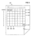
- FIG. 3 shows a grid 300 of multiple-color fluid targets 306A, 306B, ..., 306K ejected on the media 108 that have different combinations of cyan fluid and magenta fluid, and which is used to ensure that ejections of cyan fluid and magenta have substantially identical fluid drop masses, according to an embodiment of the invention.
- the multiple-color fluid targets 306A, 306B, ..., 306K of the grid 300 are collectively referred to as the fluid targets 306.
- the amount of cyan fluid is adjusted over the columns 302A, 302B, 302C, ..., 302N, collectively referred to as the columns 302, by varying the amount of energy used to eject cyan fluid drops within the targets 306 in each of the columns 302.
- the amount of magenta fluid is adjusted over the rows 304A, 304B, 304C, ..., 304N, collectively referred to as the rows 304, by varying the amount of energy used to eject magenta fluid drops within the targets 306 in each of the rows 304.
- the amount of energy used to eject cyan fluid drops within the targets 306 in the column 302A is lower than the amount of energy used to eject cyan fluid drops within the targets 306 in the column 302B
- the amount of energy used to eject cyan fluid drops within the targets 306 in the column 302B is lower than the amount of energy used to eject cyan fluid drops within the targets 306 in the column 302C, and so on.
- the amount of energy used to eject magenta fluid drops within the targets 306 in the row 304A is lower than the amount of energy used to eject magenta fluid drops within the targets in the row 304B
- the amount of every used to eject magenta fluid drops within the targets 306 in the row 304B is lower than the amount of energy used to eject magenta fluid drops within the targets 306 in the row 304C, and so on. Therefore, in each of the multiple-color fluid-drop targets 306, there is a unique combination of the energy used to eject cyan fluid and the energy used to eject magenta fluid.
- the grid 300 of the multiple-color fluid targets 306 is achieved by having the printheads 110C and 110M of the fluid-ejection mechanism 102 eject fluid onto the media 108 as prescribed. Furthermore, each of the multiple-color fluid targets 306 has a combination of two colored fluids, cyan and magenta fluid, in FIG. 3 for illustrative and descriptive clarity. In actuality, each of the multiple-color fluid targets 306 has a combination of all the differently colored fluids that the printheads 110 of the fluid-ejection mechanism 102 are able to eject. In the case of the fluid-ejection mechanism 102, this means that in actuality the fluid-targets 306 would have different combinations of cyan, magenta, yellow, and black fluids, as can be appreciated by those of ordinary skill within the art.
- the sensing mechanism 104 is employed to determine the most color-neutral target of the multiple-color fluid targets 306. This can be accomplished by measuring the chroma value of each of the fluid targets 306, and determining which of the targets 306 has the lowest, or minimum, chroma value.
- the most color-neutral target is the one of the fluid targets 306 that has substantially equal fluid drop masses of both cyan fluid and magenta fluid.
- the amount of energy used to eject the cyan fluid drops within the targets 306 in the columns 302A, 302B, 302C, ..., 302N may be E A , E B , E C , ..., E N , respectively.
- the amount of energy used to eject the cyan fluid drops within the targets 306 in the rows 304A, 304B, 304C, ..., 304N may also be E A , E B , E C , ..., E N , respectively.
- the resulting fluid drop mass of the magenta fluid drops may be less than that of the cyan fluid drops.
- those fluid targets identified by the column 302A and the row 304A, the column 302B and the row 304B, and so on, resulting from using the same amount of energy to eject both cyan and magenta fluid drops, are not color neutral because the cyan fluid drops are larger than the magenta fluid drops in these targets.
- the fluid target identified by the column 302B and the row 304C is the most color neutral, even though the amount of energy used to eject the magenta fluid drops in this target is greater than the amount of energy used to eject the cyan fluid drops in the target.
- a fluid target would nevertheless be most color-neutral target where the fluid drop masses, or sizes, of the cyan fluid drops and the magenta fluid drops are substantially equal to each other. Having substantially equal fluid drop masses within this fluid target means that the target yields a minimal chroma value by the sensing mechanism 104, such that it is selected as the most color-neutral fluid target.
- the energy used to eject the cyan fluid drops within the most color-neutral target of the multiple-color fluid targets 306, and the energy used to eject the magenta fluid drops within this most color-neutral target, is stored by the controller 106 for subsequent ejections of cyan and magenta fluid drops by the printheads 110C and 110M of the fluid-ejection mechanism 102. That is, the controller 106 adjusts the energy used to eject cyan and magenta fluid by determining the energy used to eject cyan and magenta fluid within the most color-neutral target. Thereafter, when cyan and magenta fluid is to be ejected, the resulting cyan and magenta fluid drops have substantially identical fluid drop masses, or sizes.
- FIG. 4 shows a method 400 for adjusting fluid-ejection energy to yield substantially identical fluid drop masses that summarizes and generalizes the foregoing description, according to an embodiment of the invention.
- Multiple-color fluid targets are output, via fluid ejection, by varying the energy used to eject fluid drops of each fluid color of each target (402).
- each of the fluid targets 306 has a different combination of cyan and magenta fluid, because each of the fluid targets 306 was generated using a different fluid-ejection energy for the cyan and magenta fluid.
- each multiple-color fluid target is output such that the energy used for each of these differently colored fluids varies over the targets.
- the most color-neutral multiple-color fluid target is determined (404). This can be accomplished by scanning each fluid target to determine its chroma value (406), and selecting the target having the lowest, or minimum, chroma value as the most color neutral target (408). Finally, the energy used to eject fluid for each fluid color is adjusted, by determining the energy used to eject fluid for each fluid color within the most color-neutral target (410). The energy determined and adjusted for each color of fluid is then used in subsequent fluid ejection so that substantially identical fluid drop masses are achieved.
- FIG. 5 shows a method 500 that is consistent with the method 400, but which is performed by the controller 106 to achieve substantially identical fluid drop masses of differently colored fluids.
- the method 400 may thus be implemented as a computer program stored on a computer-readable medium.
- the medium may be a volatile or a non-volatile medium.
- the medium may also be a magnetic medium, such as a floppy disk, hard disk drive, or tape cartridge, an optical medium, such as an optical disc, and/or a semiconductor medium, like a random-access memory or a flash memory.
- the controller 106 first causes the fluid-ejection mechanism 102 to output multiple-color fluid targets by varying the energy used to eject fluid drops of each fluid color of each fluid target (502), as has been described. Next, the controller 106 causes the scanning mechanism 104 to scan each fluid target to determine its chroma value (504). The controller 106 finally adjusts the energy used to eject fluid for each fluid color by determining the energy used to eject fluid for each fluid color within the fluid target having the minimum, or lowest, chroma value (506).
- the grid 300 of multiple-color fluid targets 306 in FIG. 3 is generated by varying the energy used to eject fluid by the printheads 110 of the fluid-ejection mechanism 102.
- the most color-neutral target of the fluid targets 306 is identified.
- the different levels of energy employed to eject fluid by the printheads 110 within the most color-neutral target are then subsequently used to eject fluid, such that substantially identical fluid drop mass is ensured.
- the grid of multiple-color fluid targets 306 in FIG. 3 can be generated by varying the number of fluid drops of ink of each of the fluid colors of each of the targets 306, where the same level of energy is used to eject the fluid drops of each of the targets 306, for a given fluid color. That is, the amount of cyan fluid is adjusted over the columns 302 by varying the number of cyan fluid drops that are ejected within the targets 306 in each of the columns 302, without varying the fluid-ejection energy. Similarly, the amount of magenta fluid is adjusted over the rows 304 by varying the number of magenta drops that are ejected within the targets 306 in each of the rows 304, without varying the fluid-ejection energy.
- the number of cyan fluid drops within the targets 306 in the column 302A may be lower than the number of cyan fluid drops within the targets 306 in the column 302B, the number of cyan fluid drops within the targets 306 in the column 302B may be lower than the number of cyan fluid drops within the targets 306 in the column 302C, and so on.
- the number of magenta fluid drops within the targets 306 in the row 304A may be lower than the number of cyan fluid drops within the targets 306 in the row 304B, the number of magenta fluid drops within the targets 306 in the row 304B may be lower than the number of magenta fluid drops within the targets 306 in the row 304C, and so on.
- each of the multiple-color fluid-drop targets 306 there is a unique combination of the number of cyan fluid drops and the number of magenta fluid drops, even though the same fluid-ejection energy is used to eject the cyan fluid drops in each of the targets 306, and the same fluid-ejection energy is used to eject the magenta fluid drops in each of the targets 306.
- the sensing mechanism 104 is employed to determine the most color-neutral target of the multiple-color fluid targets 306.
- the number of fluid drops ejected for each fluid color within the most color-neutral target is compared to a reference number of fluid drops of the fluid color to ensure color neutrality.
- the most color-neutral target may be the target in which eighty cyan fluid drops and forty magenta fluid drops were ejected.
- the reference number of fluid drops of each these colors may be fifty drops. Therefore, the energy used to eject fluid for each fluid color is adjusted based on the number of fluid drops ejected for the fluid color on the most color-neutral target, compared to the reference number of fluid drops that should have been ejected, to ensure color neutrality.
- a linear relationship between energy and fluid drop mass is employed to adjust the energy to eject a fluid drop based on the number of drops ejected on the most color-neutral target compared to a reference number of fluid drops, for each color of fluid.
- the adjustment is 100 % ⁇ 80 - 50 80 , or an increase of 38%.
- the adjustment is 100 % ⁇ 40 - 50 40 , or a decrease of 25%. Assuming a linear relationship between energy and fluid drop mass may particularly be appropriate where the number of drops for a given fluid color on the most color-neutral target does not vary by too much from the reference number of drops.
- FIG. 6 shows a graph 600 of an example non-linear relationship between fluid-ejection energy and fluid-drop mass, according to an embodiment of the invention.
- the y-axis 602 indicates fluid drop mass as a function of fluid-ejection energy on the x-axis 604.
- the line 606 is non-linear, such that a given percentage increase or decrease in fluid-ejection energy generally does not yield a corresponding percentage increase or decrease in fluid drop mass.
- the middle portion 608 of the line 606 is in fact substantially linear.
- the non-linear relationship between fluid-ejection energy and fluid-drop mass represented as the line 606 of the graph 600 can be utilized as follows to adjust fluid-ejection energy to achieve color neutrality.
- An initial point on the line 606 is known based on the fluid-ejection energy used to eject each of the drops in the most color-neutral multiple-color target.
- the Adjustment factor provided above when assuming a linear relationship between fluid-ejection energy and fluid drop mass instead is used to indicate how far to go up or down on the y-axis 602. Where a horizontal line drawn at this new level on the y-axis 602 intersects the line 606 therefore indicates the new fluid-ejection energy to be used to ensure color neutrality.
- the corresponding point on the line 606 is not a corresponding percentage right or left on the x-axis 604 as compared to the Adjustment factor used to go up or down on the y-axis 602.
- FIG. 7 shows how the example non-linear relationship between fluid drop mass and fluid-ejection energy, represented as the line 606 of the graph 600, may be used to determine the fluid-ejection energy needed to ensure color neutrality where eighty cyan drops are ejected on the most color-neutral target, and the reference number of cyan fluid drops is fifty, according to an embodiment of the invention.
- the initial point 708 provides the fluid drop mass M 1 for the fluid-ejection energy E 1 that is used to eject each of the eighty cyan drops on the most color-neutral target.
- FIG. 8 shows how the example non-linear relationship between fluid drop mass and fluid-ejection energy, represented as the line 606 of the graph 600, may be used to determine the fluid-ejection energy needed to ensure color neutrality where forty magenta drops are ejected on the most color-neutral target, and the reference number of magenta drops is fifty, according to an embodiment of the invention.
- the initial point 802 provides the fluid drop mass M 1 for the fluid-ejection energy E 1 that is used to eject each of the forty cyan drops on the most color-neutral target.
- the non-linear relationship between fluid drop mass and fluid-ejection energy is assumed as a given function.
- the firmware thereof may store a function expressing the non-linear relationship between drop mass and energy.
- a function may have been determined at the factory or in laboratory conditions, or based on expected behavior of a given fluid-ejection mechanism and/or its constituent printheads and types of ink.
- the relationship between fluid drop mass and fluid-ejection energy may be determined dynamically, for a given fluid-ejection assembly and/or a given fluid-ejection device, such as either before or after generating the grid 300 of FIG. 3 .
- the fluid-ejection assembly may include a fluid drop mass sensor that is able to measure the mass of a drop of fluid that has been ejected.
- the fluid drop mass sensor may be a drop-detect sensing mechanism, or another type of fluid drop mass sensor.
- a given printhead of the fluid-ejection assembly is caused to output fluid drops at different fluid-ejection energy levels. At each energy level, the drop mass of the ejected fluid drop is determined. Based on this data, the relationship between drop mass and fluid-ejection energy may be determined. For instance, the data may be stored within a table, and further data points may be interpolated from the data as needed. As another example, curve-fitting or other approaches may be used to mathematically express the non-linear relationship between drop mass and fluid-ejection energy.
- FIG. 9 shows a method 400' for adjusting fluid-ejection energy to yield substantially identical fluid drop masses that summarizes and generalizes the foregoing description, according to an exemplary embodiment of the invention.
- the method of FIG. 9 is denoted as the method 400' because it is a variation of the method 400 of FIG. 4 that has been described.
- Multiple-color fluid targets are output, via fluid ejection, by varying the number of fluid drops of each fluid color of each target (402').
- 402' differs from 402 of FIG. 4 in that the number of fluid drops is varied in 402', whereas the fluid-ejection energy is varied in 402 of FIG. 4 .
- the most color-neutral target is then determined (404), as has been described in relation to the method 400 of FIG. 4 .
- 410' differs from 410 in how the energy used to eject fluid for each fluid color is adjusted. 410' is performed as has been described in this section of the detailed description. A linear relationship may be assumed between fluid drop mass and fluid-ejection energy, or a non-linear relationship may be assumed or otherwise determined between fluid drop mass and fluid-ejection energy, as has been described.
- FIG. 10 shows a method 1000 for determining the relationship, non-linear or otherwise, between fluid drop mass and fluid-ejection energy for a given fluid color, according to an embodiment of the invention.
- Fluid drops are output, such that the energy used to eject each drop is different (1002).
- the drop mass of each fluid drop is determined as each drop of fluid is ejected (1004). From this information - the drop mass-energy pairs - the relationship between fluid-ejection energy and fluid drop mass is determined (1006). For instance, additional data points may be interpolated, or a function may be fitted onto the existing data points.
- the energy used to eject fluid is adjusted to ensure that fluid drop ejections yield fluid drop masses having a consistent ratio. That is, in the exemplary embodiment, the energy used to eject fluid is adjusted to yield substantially identical fluid drop masses, which means that the ratio between two such fluid drop masses is substantially 1:1.
- the energy used to eject fluid can be adjusted to yield fluid drop masses having ratios other than 1:1, but where the ratios are still consistent, or otherwise substantially constant.
- FIG. 11 shows a rudimentary image-forming device 1100, according to an embodiment of the invention.
- the image-forming device 1100 is for forming images on media, and is specifically a fluid-ejection device, on account of its inclusion of the fluid-ejection assembly 100.
- the fluid-ejection assembly 100 may be an inkjet-printing assembly, such that the image-forming device 1100 is an inkjet-printing device.
- the image-forming device 1100 includes a media-movement assembly 1102 and the controller 106, and may also include other components not depicted in FIG. 11 .
- the controller 106 is depicted in the embodiment of FIG. 1 as being a part of the fluid-ejection assembly 100, in the embodiment of FIG.
- the media-movement assembly 1102 includes motors, rollers, and other components to advance the media relative to the fluid-ejection assembly 100, so that the assembly 100 is able to eject fluid thereon for image formation.
- the fluid-ejection assembly 100 is thus capable of ejecting differently color fluids onto media, and of sensing at least a chroma value of different parts of the media, as has been described.
- the controller 106 causes the fluid-ejection assembly 100 to output multiple-color fluid targets onto the media and to sense the chroma value of each target.
- the controller 106 also adjusts the energy used to eject each of one or more of the differently color fluids, based on the multiple-color fluid target having a minimum chroma value, as has also been described. Either the energy used to eject fluid drops of the differently colored fluids may vary over the fluid targets, or the number of fluid drops of the differently colored fluids may vary over the targets.
- the assembly 100 may include the printheads 110, such as inkjet printheads, and the sensing mechanism 104, such as an optical sensor, as has been described in relation to FIG. 1 .
Description
- Inkjet printers have become popular for printing on media, especially when precise printing of color images is needed. For instance, such printers have become popular for printing color image files generated using digital cameras, for printing color copies of business presentations, and so on. Industrial usage of inkjet printers has also become common for high-speed color printing on large numbers of items. An inkjet printer is more generically a fluid-ejection device that ejects drops of fluid, such as ink, onto media, such as paper.
- To ensure the highest quality of inkjet printing output, many variables usually have to be considered. One such variable is the fluid drop mass, or size, of ink drops that each inkjet printhead outputs. An inkjet printer may include a number of different printheads, corresponding, for instance, to a particular color model, such as the cyan-magenta-yellow-black (CMYK) color model, so that nearly any color can be achieved by outputting various combinations of the differently colored inks. For proper color matching, the fluid drop masses output by the different printheads should have constant, or consistent, ratios with respect to one another.
- However, manufacturing, environmental, and other variations and factors can affect the fluid drop masses output by the inkjet printheads of inkjet printers. Different printheads within the same inkjet printer may output ink drops that have different fluid drop masses. An inkjet printhead outputting cyan ink, for instance, may output cyan ink drops that have different drop masses than those of magenta ink drops output by another inkjet printhead. Such a mismatch in ink drop masses within the same printer can result in less than optimal inkjet printing output quality.
-
EP 1 292 117 A - Late published
EP 1 398 956 A1 -
US 2001/024583 A1 describes a printing apparatus and a driving condition setting method for a printhead. The printing apparatus is capable of setting driving conditions in consideration of conditions on the printing apparatus main body side. The printing apparatus includes a printing head having a plurality of print elements and a head driver for generating a pulse-like driving signal supplied to the printhead. The apparatus sets driving conditions for a printhead with test patterns obtained by simultaneously driving a predetermined number of the print elements. The test patterns are printed on the printing medium while the pulse width of the driving signal is decreased stepwise from a predetermined value. Then, a boundary value of a pulse width with which a print element is not properly driven, is obtained from the test patterns. The pulse width of a driving signal generated by the head driver is controlled on the basis of the boundary value. -
EP 1 364 796 A - The present invention provides a method according to
claim 1 as well as an image-forming device according to claim 5. Preferred embodiments of the invention are defined in the dependent claims. - The drawings referenced herein form a part of the specification. Features shown in the drawing are meant as illustrative of only some embodiments of the invention, and not of all embodiments of the invention, unless otherwise explicitly indicated, and implications to the contrary are otherwise not to be made.
-
FIG. 1 is a diagram of a rudimentary fluid-ejection assembly, according to an embodiment of the invention. -
FIG. 2 is a diagram depicting how the same fluid-ejection energy may result in fluid drops of different masses, or sizes, over different printheads, in accordance with which embodiments of the invention may be practiced. -
FIG. 3 is a diagram of an example grid of multiple-color fluid targets output onto media via fluid ejection, according to an exemplary embodiment of the invention. -
FIG. 4 is a flowchart of a method to adjust fluid-ejection energy to yield substantially identical fluid drop masses for different fluid colors, according to an exemplary embodiment of the invention. -
FIG. 5 is a flowchart of a method for performance by the fluid-ejection assembly ofFIG. 1 to adjust fluid-ejection energy to yield substantially identical fluid drop masses. -
FIG. 6 is a graph of an example non-linear relationship between fluid drop mass and fluid-ejection energy, according to an exemplary embodiment of the invention. -
FiGs. 7 and8 are graphs illustratively depicting how the example non-linear relationship ofFIG. 6 may be employed to adjust fluid-ejection energy to yield substantially identical fluid drop masses, according to an exemplary embodiment of the invention. -
FIG. 9 is a flowchart of a method to adjust fluid-ejection energy to yield substantially identical fluid drop mass for different fluid colors that is different than the method ofFIG. 4 , according to an exemplary embodiment of the invention. -
FIG. 10 is a flowchart of a method to determine the relationship between fluid-ejection energy and fluid drop mass, according to an exemplary embodiment of the invention. -
FIG. 11 is a block diagram of a rudimentary image-forming device, according to an embodiment of the invention. - In the following detailed description of exemplary embodiments of the invention, reference is made to the accompanying drawings that form a part hereof, and in which is shown by way of illustration specific exemplary embodiments in which the invention may be practiced. These embodiments are described in sufficient detail to enable those skilled in the art to practice the invention. Other embodiments may be utilized, and logical, mechanical, and other changes may be made without departing from the scope of the present invention. The following detailed description is, therefore, not to be taken in a limiting sense, and the scope of the present invention is defined only by the appended claims.
-
FIG. 1 shows a rudimentary fluid-ejection assembly 100, according to an embodiment of the invention. The fluid-ejection assembly 100 includes a fluid-ejection mechanism 102, asensing mechanism 104, and acontroller 106. The fluid-ejection assembly 100 may be an inkjet-printing assembly, and may be a part of a fluid-ejection device, such as an inkjet-printing device. The fluid-ejection mechanism 102 is depicted as includingprintheads printheads media 108, such as paper, or another type of media. The printheads 110 thus eject differently colored fluids 112 in accordance with the cyan-magenta-yellow-black (CMYK) color model inFIG. 1 . However, alternatively, the printheads 110 may eject differently color fluids 112 in accordance with a different color model. - The
sensing mechanism 104 may include or be an optical sensor that emits light 114 towards themedia 108, and detects, or senses, light 116 that is reflected back off themedia 108 as a result. Thesensing mechanism 104 may provide luminance, hue, and chroma values to thecontroller 106, as indicated by thearrow 118, based on the part of themedia 108 that the light 114 is incident to, as reflected back as the reflectedlight 116. Thecontroller 106 controls the energy levels that cause the printheads 110 of the fluid-ejection mechanism 102 to fire, or eject ink, where the printheads 110 may be thermal-inkjet (TIJ), piezoelectric, or another type of printheads. Thecontroller 106, based on the chroma or other values provided by thesensing mechanism 104, is able to individually adjust the energy used to eject the colored fluids 112 by the printheads 110 of the fluid-ejection mechanism 102, as described in detail later in the detailed description. Thecontroller 106 may include hardware, software, or a combination of hardware and software. -
FIG. 2 shows an example of the printheads 110 of the fluid-ejection mechanism 102 ejecting the fluid drops 112 such that the drops 112 have different fluid drop masses, or sizes, even though the same energy is used to cause each of the printheads 110 to eject its corresponding one of the drops 112, in conjunction with which embodiments of the invention may be implemented. Each of the printheads 110 receives an energy E to eject its corresponding one of the drops 112. Theprintheads printhead 110M ejects thefluid drop 112M that has a drop mass M2 that is less than the drop mass M1. Theprinthead 110Y ejects thefluid drop 112Y that has a drop mass M3 that is greater than the drop mass M1. - That is, the
printheads printheads -
FIG. 3 shows agrid 300 of multiple-color fluid targets media 108 that have different combinations of cyan fluid and magenta fluid, and which is used to ensure that ejections of cyan fluid and magenta have substantially identical fluid drop masses, according to an embodiment of the invention. The multiple-color fluid targets grid 300 are collectively referred to as the fluid targets 306. The amount of cyan fluid is adjusted over thecolumns rows - For instance, the amount of energy used to eject cyan fluid drops within the targets 306 in the
column 302A is lower than the amount of energy used to eject cyan fluid drops within the targets 306 in thecolumn 302B, the amount of energy used to eject cyan fluid drops within the targets 306 in thecolumn 302B is lower than the amount of energy used to eject cyan fluid drops within the targets 306 in thecolumn 302C, and so on. Similarly, the amount of energy used to eject magenta fluid drops within the targets 306 in therow 304A is lower than the amount of energy used to eject magenta fluid drops within the targets in therow 304B, the amount of every used to eject magenta fluid drops within the targets 306 in therow 304B is lower than the amount of energy used to eject magenta fluid drops within the targets 306 in therow 304C, and so on. Therefore, in each of the multiple-color fluid-drop targets 306, there is a unique combination of the energy used to eject cyan fluid and the energy used to eject magenta fluid. - The
grid 300 of the multiple-color fluid targets 306 is achieved by having theprintheads ejection mechanism 102 eject fluid onto themedia 108 as prescribed. Furthermore, each of the multiple-color fluid targets 306 has a combination of two colored fluids, cyan and magenta fluid, inFIG. 3 for illustrative and descriptive clarity. In actuality, each of the multiple-color fluid targets 306 has a combination of all the differently colored fluids that the printheads 110 of the fluid-ejection mechanism 102 are able to eject. In the case of the fluid-ejection mechanism 102, this means that in actuality the fluid-targets 306 would have different combinations of cyan, magenta, yellow, and black fluids, as can be appreciated by those of ordinary skill within the art. - The
sensing mechanism 104 is employed to determine the most color-neutral target of the multiple-color fluid targets 306. This can be accomplished by measuring the chroma value of each of the fluid targets 306, and determining which of the targets 306 has the lowest, or minimum, chroma value. The most color-neutral target is the one of the fluid targets 306 that has substantially equal fluid drop masses of both cyan fluid and magenta fluid. - For example, the amount of energy used to eject the cyan fluid drops within the targets 306 in the
columns rows column 302A and therow 304A, thecolumn 302B and therow 304B, and so on, resulting from using the same amount of energy to eject both cyan and magenta fluid drops, are not color neutral because the cyan fluid drops are larger than the magenta fluid drops in these targets. - For instance, it may be determined that the fluid target identified by the
column 302B and therow 304C is the most color neutral, even though the amount of energy used to eject the magenta fluid drops in this target is greater than the amount of energy used to eject the cyan fluid drops in the target. Such a fluid target would nevertheless be most color-neutral target where the fluid drop masses, or sizes, of the cyan fluid drops and the magenta fluid drops are substantially equal to each other. Having substantially equal fluid drop masses within this fluid target means that the target yields a minimal chroma value by thesensing mechanism 104, such that it is selected as the most color-neutral fluid target. - The energy used to eject the cyan fluid drops within the most color-neutral target of the multiple-color fluid targets 306, and the energy used to eject the magenta fluid drops within this most color-neutral target, is stored by the
controller 106 for subsequent ejections of cyan and magenta fluid drops by theprintheads ejection mechanism 102. That is, thecontroller 106 adjusts the energy used to eject cyan and magenta fluid by determining the energy used to eject cyan and magenta fluid within the most color-neutral target. Thereafter, when cyan and magenta fluid is to be ejected, the resulting cyan and magenta fluid drops have substantially identical fluid drop masses, or sizes. -
FIG. 4 shows amethod 400 for adjusting fluid-ejection energy to yield substantially identical fluid drop masses that summarizes and generalizes the foregoing description, according to an embodiment of the invention. Multiple-color fluid targets are output, via fluid ejection, by varying the energy used to eject fluid drops of each fluid color of each target (402). For instance, in the case of the example ofFIG. 3 , each of the fluid targets 306 has a different combination of cyan and magenta fluid, because each of the fluid targets 306 was generated using a different fluid-ejection energy for the cyan and magenta fluid. In the case of cyan, magenta, yellow, and black fluid, each multiple-color fluid target is output such that the energy used for each of these differently colored fluids varies over the targets. - Next, the most color-neutral multiple-color fluid target is determined (404). This can be accomplished by scanning each fluid target to determine its chroma value (406), and selecting the target having the lowest, or minimum, chroma value as the most color neutral target (408). Finally, the energy used to eject fluid for each fluid color is adjusted, by determining the energy used to eject fluid for each fluid color within the most color-neutral target (410). The energy determined and adjusted for each color of fluid is then used in subsequent fluid ejection so that substantially identical fluid drop masses are achieved.
-
FIG. 5 shows amethod 500 that is consistent with themethod 400, but which is performed by thecontroller 106 to achieve substantially identical fluid drop masses of differently colored fluids. Themethod 400 may thus be implemented as a computer program stored on a computer-readable medium. The medium may be a volatile or a non-volatile medium. The medium may also be a magnetic medium, such as a floppy disk, hard disk drive, or tape cartridge, an optical medium, such as an optical disc, and/or a semiconductor medium, like a random-access memory or a flash memory. - The
controller 106 first causes the fluid-ejection mechanism 102 to output multiple-color fluid targets by varying the energy used to eject fluid drops of each fluid color of each fluid target (502), as has been described. Next, thecontroller 106 causes thescanning mechanism 104 to scan each fluid target to determine its chroma value (504). Thecontroller 106 finally adjusts the energy used to eject fluid for each fluid color by determining the energy used to eject fluid for each fluid color within the fluid target having the minimum, or lowest, chroma value (506). - In the example of the invention described in the previous section of the detailed description, the
grid 300 of multiple-color fluid targets 306 inFIG. 3 is generated by varying the energy used to eject fluid by the printheads 110 of the fluid-ejection mechanism 102. The most color-neutral target of the fluid targets 306 is identified. The different levels of energy employed to eject fluid by the printheads 110 within the most color-neutral target are then subsequently used to eject fluid, such that substantially identical fluid drop mass is ensured. - In an exemplary embodiment of the invention, however, the grid of multiple-color fluid targets 306 in
FIG. 3 can be generated by varying the number of fluid drops of ink of each of the fluid colors of each of the targets 306, where the same level of energy is used to eject the fluid drops of each of the targets 306, for a given fluid color. That is, the amount of cyan fluid is adjusted over the columns 302 by varying the number of cyan fluid drops that are ejected within the targets 306 in each of the columns 302, without varying the fluid-ejection energy. Similarly, the amount of magenta fluid is adjusted over the rows 304 by varying the number of magenta drops that are ejected within the targets 306 in each of the rows 304, without varying the fluid-ejection energy. - For instance, the number of cyan fluid drops within the targets 306 in the
column 302A may be lower than the number of cyan fluid drops within the targets 306 in thecolumn 302B, the number of cyan fluid drops within the targets 306 in thecolumn 302B may be lower than the number of cyan fluid drops within the targets 306 in thecolumn 302C, and so on. Similarly, the number of magenta fluid drops within the targets 306 in therow 304A may be lower than the number of cyan fluid drops within the targets 306 in therow 304B, the number of magenta fluid drops within the targets 306 in therow 304B may be lower than the number of magenta fluid drops within the targets 306 in therow 304C, and so on. Therefore, in each of the multiple-color fluid-drop targets 306, there is a unique combination of the number of cyan fluid drops and the number of magenta fluid drops, even though the same fluid-ejection energy is used to eject the cyan fluid drops in each of the targets 306, and the same fluid-ejection energy is used to eject the magenta fluid drops in each of the targets 306. - As before, the
sensing mechanism 104 is employed to determine the most color-neutral target of the multiple-color fluid targets 306. The number of fluid drops ejected for each fluid color within the most color-neutral target is compared to a reference number of fluid drops of the fluid color to ensure color neutrality. For example, the most color-neutral target may be the target in which eighty cyan fluid drops and forty magenta fluid drops were ejected. However, the reference number of fluid drops of each these colors may be fifty drops. Therefore, the energy used to eject fluid for each fluid color is adjusted based on the number of fluid drops ejected for the fluid color on the most color-neutral target, compared to the reference number of fluid drops that should have been ejected, to ensure color neutrality. - In the case where eighty cyan fluid drops are ejected on the most color-neutral target, this means that eighty cyan fluid drops had to be ejected to achieve color neutrality, where the reference number is much less, at fifty cyan fluid drops. Therefore, the energy used to eject a cyan fluid drop is increased, based on the comparison between the actual eighty cyan fluid drops on the most color-neutral target and the reference fifty cyan fluid drops, so that fifty cyan fluid drops in future cyan fluid ejections achieves color neutrality. Similarly, in the case where forty magenta fluid drops are ejected on the most color-neutral target, this means that forty magenta fluid drops had to be ejected to achieve color neutrality, where the reference number is greater, at fifty magenta fluid drops. Therefore, the energy used to eject a magenta fluid drop is decreased, based on the comparison between the actual forty magenta fluid drops on the most color-neutral target and the reference fifty magenta fluid drops, so that fifty magenta fluid drops in future magenta fluid ejections achieves color neutrality.
- In one exemplary embodiment, a linear relationship between energy and fluid drop mass is employed to adjust the energy to eject a fluid drop based on the number of drops ejected on the most color-neutral target compared to a reference number of fluid drops, for each color of fluid. The adjustment can be represented as:


- In another exemplary embodiment, the relationship between energy and fluid drop mass is non-linear.
FIG. 6 shows agraph 600 of an example non-linear relationship between fluid-ejection energy and fluid-drop mass, according to an embodiment of the invention. The y-axis 602 indicates fluid drop mass as a function of fluid-ejection energy on thex-axis 604. Theline 606 is non-linear, such that a given percentage increase or decrease in fluid-ejection energy generally does not yield a corresponding percentage increase or decrease in fluid drop mass. However, it is noted that themiddle portion 608 of theline 606 is in fact substantially linear. - The non-linear relationship between fluid-ejection energy and fluid-drop mass represented as the
line 606 of thegraph 600 can be utilized as follows to adjust fluid-ejection energy to achieve color neutrality. An initial point on theline 606 is known based on the fluid-ejection energy used to eject each of the drops in the most color-neutral multiple-color target. The Adjustment factor provided above when assuming a linear relationship between fluid-ejection energy and fluid drop mass instead is used to indicate how far to go up or down on the y-axis 602. Where a horizontal line drawn at this new level on the y-axis 602 intersects theline 606 therefore indicates the new fluid-ejection energy to be used to ensure color neutrality. Because the relationship between fluid-ejection energy and the fluid drop mass is non-linear, however, the corresponding point on theline 606 is not a corresponding percentage right or left on thex-axis 604 as compared to the Adjustment factor used to go up or down on the y-axis 602. - For example,
FIG. 7 shows how the example non-linear relationship between fluid drop mass and fluid-ejection energy, represented as theline 606 of thegraph 600, may be used to determine the fluid-ejection energy needed to ensure color neutrality where eighty cyan drops are ejected on the most color-neutral target, and the reference number of cyan fluid drops is fifty, according to an embodiment of the invention. Theinitial point 708 provides the fluid drop mass M1 for the fluid-ejection energy E1 that is used to eject each of the eighty cyan drops on the most color-neutral target. Because eighty cyan drops is an increase of 38% over the number of reference cyan drops, fifty - i.e., the Adjustment factor previously described - thelevel 706 on the y-axis 602 is correspondingly increased by 38% to thelevel 708, as represented by thearrow 704. Thenew level 708 corresponds to the fluid drop mass M 2, and intersects theline 606 at thepoint 710. The corresponding fluid-ejection energy E 2 on thex-axis 604 at thispoint 710 is therefore the fluid-ejection energy to be used when ejecting cyan fluid drops to achieve color neutrality. It is noted that in all likelihood
- As another example,
FIG. 8 shows how the example non-linear relationship between fluid drop mass and fluid-ejection energy, represented as theline 606 of thegraph 600, may be used to determine the fluid-ejection energy needed to ensure color neutrality where forty magenta drops are ejected on the most color-neutral target, and the reference number of magenta drops is fifty, according to an embodiment of the invention. Theinitial point 802 provides the fluid drop mass M1 for the fluid-ejection energy E1 that is used to eject each of the forty cyan drops on the most color-neutral target. Because forty cyan drops is a decrease of 25% from the number of reference magenta drops, fifty-i.e., the Adjustment factor previously described - thelevel 806 on the y-axis 602 is correspondingly decreased by 25% to thelevel 808, as represented by thearrow 804. Thenew level 808 corresponds to the fluid drop mass M2 , and intersects theline 606 at thepoint 810. The corresponding fluid-ejection energy E2 on thex-axis 604 at thispoint 810 is therefore the fluid-ejection energy to be used when ejection magenta fluid drops to achieve color neutrality. It is noted that in all likelihood
- In one exemplary embodiment, the non-linear relationship between fluid drop mass and fluid-ejection energy is assumed as a given function. For instance, within a given fluid-ejection assembly and/or a given fluid-ejection device, the firmware thereof may store a function expressing the non-linear relationship between drop mass and energy. Such a function may have been determined at the factory or in laboratory conditions, or based on expected behavior of a given fluid-ejection mechanism and/or its constituent printheads and types of ink. Alternatively, the relationship between fluid drop mass and fluid-ejection energy may be determined dynamically, for a given fluid-ejection assembly and/or a given fluid-ejection device, such as either before or after generating the
grid 300 ofFIG. 3 . - For example, the fluid-ejection assembly may include a fluid drop mass sensor that is able to measure the mass of a drop of fluid that has been ejected. The fluid drop mass sensor may be a drop-detect sensing mechanism, or another type of fluid drop mass sensor. A given printhead of the fluid-ejection assembly is caused to output fluid drops at different fluid-ejection energy levels. At each energy level, the drop mass of the ejected fluid drop is determined. Based on this data, the relationship between drop mass and fluid-ejection energy may be determined. For instance, the data may be stored within a table, and further data points may be interpolated from the data as needed. As another example, curve-fitting or other approaches may be used to mathematically express the non-linear relationship between drop mass and fluid-ejection energy.
-
FIG. 9 shows a method 400' for adjusting fluid-ejection energy to yield substantially identical fluid drop masses that summarizes and generalizes the foregoing description, according to an exemplary embodiment of the invention. The method ofFIG. 9 is denoted as the method 400' because it is a variation of themethod 400 ofFIG. 4 that has been described. Multiple-color fluid targets are output, via fluid ejection, by varying the number of fluid drops of each fluid color of each target (402'). 402' differs from 402 ofFIG. 4 in that the number of fluid drops is varied in 402', whereas the fluid-ejection energy is varied in 402 ofFIG. 4 . The most color-neutral target is then determined (404), as has been described in relation to themethod 400 ofFIG. 4 . - Finally, the energy used to eject fluid for each fluid color is adjusted, based on the number of fluid drops ejected for each fluid color compared to a reference number of fluid drops that should have been ejected to ensure color neutrality (410'). 410' differs from 410 in how the energy used to eject fluid for each fluid color is adjusted. 410' is performed as has been described in this section of the detailed description. A linear relationship may be assumed between fluid drop mass and fluid-ejection energy, or a non-linear relationship may be assumed or otherwise determined between fluid drop mass and fluid-ejection energy, as has been described.
- For example,
FIG. 10 shows amethod 1000 for determining the relationship, non-linear or otherwise, between fluid drop mass and fluid-ejection energy for a given fluid color, according to an embodiment of the invention. Fluid drops are output, such that the energy used to eject each drop is different (1002). The drop mass of each fluid drop is determined as each drop of fluid is ejected (1004). From this information - the drop mass-energy pairs - the relationship between fluid-ejection energy and fluid drop mass is determined (1006). For instance, additional data points may be interpolated, or a function may be fitted onto the existing data points. - The examples and exemplary embodiments of the invention that have been described in the previous two sections of the detailed description in relation to
FIGs. 3-9 adjust the energy used to eject fluid to ensure that fluid drop ejections yield substantially identical fluid drop masses. However, this is for exemplary purposes only, and does not reflect limitations on all embodiments of the invention. More generally, in other embodiments of the invention, the energy used to eject fluid is adjusted to ensure that fluid drop ejections yield fluid drop masses having a consistent ratio. That is, in the exemplary embodiment, the energy used to eject fluid is adjusted to yield substantially identical fluid drop masses, which means that the ratio between two such fluid drop masses is substantially 1:1. However, in other embodiments of the invention, the energy used to eject fluid can be adjusted to yield fluid drop masses having ratios other than 1:1, but where the ratios are still consistent, or otherwise substantially constant. -
FIG. 11 shows a rudimentary image-formingdevice 1100, according to an embodiment of the invention. The image-formingdevice 1100 is for forming images on media, and is specifically a fluid-ejection device, on account of its inclusion of the fluid-ejection assembly 100. For instance, the fluid-ejection assembly 100 may be an inkjet-printing assembly, such that the image-formingdevice 1100 is an inkjet-printing device. Besides the fluid-ejection assembly 100, the image-formingdevice 1100 includes a media-movement assembly 1102 and thecontroller 106, and may also include other components not depicted inFIG. 11 . Although thecontroller 106 is depicted in the embodiment ofFIG. 1 as being a part of the fluid-ejection assembly 100, in the embodiment ofFIG. 11 thecontroller 106 is indicated as being separate from theassembly 100. The media-movement assembly 1102 includes motors, rollers, and other components to advance the media relative to the fluid-ejection assembly 100, so that theassembly 100 is able to eject fluid thereon for image formation. - The fluid-
ejection assembly 100 is thus capable of ejecting differently color fluids onto media, and of sensing at least a chroma value of different parts of the media, as has been described. Thecontroller 106 causes the fluid-ejection assembly 100 to output multiple-color fluid targets onto the media and to sense the chroma value of each target. Thecontroller 106 also adjusts the energy used to eject each of one or more of the differently color fluids, based on the multiple-color fluid target having a minimum chroma value, as has also been described. Either the energy used to eject fluid drops of the differently colored fluids may vary over the fluid targets, or the number of fluid drops of the differently colored fluids may vary over the targets. Furthermore, theassembly 100 may include the printheads 110, such as inkjet printheads, and thesensing mechanism 104, such as an optical sensor, as has been described in relation toFIG. 1 . - It is noted that, although specific embodiments have been illustrated and described herein, it will be appreciated by those of ordinary skill in the art that any arrangement is calculated to achieve the same purpose may be substituted for the specific embodiments shown. This application is intended to cover any adaptations or variations of embodiments of the present invention. Therefore, it is manifestly intended that this invention be limited only by the claims.
Claims (5)
- A method (400) comprising:determining a plurality of calibration factors for a fluid-ejection mechanism capable of ejecting a plurality of differently colored fluids (402, 404); and,adjusting an energy used to eject fluid for at least one of the plurality of fluid colors based on the plurality of calibration factors so that fluid drop ejections of the plurality of fluid colors yield fluid drop masses having a consistent ratio (410),wherein determining the plurality of calibration factors comprises:outputting a plurality of multiple-color fluid targets via fluid ejection, each multiple-color fluid target having a different combination of a plurality of fluid colors (402); and,determining a most color-neutral target of the plurality of multiple-color fluid targets, such that the energy used to eject fluid for the at least one of the plurality of fluid colors is adjusted based on the most color-neutral target (404), characterized in that outputting the plurality of multiple-color fluid targets via fluid ejection comprises varying a number of fluid drops ejected of each of the plurality of fluid colors of each multiple-color fluid target, andthe energy used to eject a fluid drop for each fluid color is adjusted based on the number of fluid drops ejected for the fluid color on the most color-neutral target, compared to a reference number of fluid drops that should have been ejected, to ensure color neutrality.
- The method of claim 1, wherein determining the most color-neutral target of the plurality of multiple-color fluid targets comprises:scanning each of the plurality of multiple-color fluid targets to determine a chroma value of each of the plurality of multiple-color fluid targets (406);selecting the most color-neutral target as one of the plurality of multiple-color fluid targets having a minimum chroma value (408).
- The method of claim 1, wherein said adjusting the energy used to eject fluid for at least one of the plurality of fluid colors comprises adjusting the energy used to eject fluid for at least one of the plurality of fluid colors so that fluid drop ejections of the plurality of fluid colors yield substantially identical fluid drop masses.
- The method of claim 1, wherein the fluid-ejection mechanism comprises a plurality of inkjet printheads, each inkjet printhead capable of ejecting a differently colored ink as one of the plurality of different color fluids.
- An image-forming device (1100) comprising:a fluid-ejection assembly capable of ejecting a plurality of differently colored fluids onto media and of sensing at least a chroma value of different parts of the media (100);a media-movement assembly to advance the media relative to the fluid-ejection assembly (1102); and,a controller set up to execute the method of any of claims 1 - 4.
Applications Claiming Priority (2)
| Application Number | Priority Date | Filing Date | Title |
|---|---|---|---|
| US760045 | 2004-01-18 | ||
| US10/760,045 US7101016B2 (en) | 2004-01-18 | 2004-01-18 | Adjustment of fluid-ejection energy to yield fluid drop masses having consistent ratio |
Publications (2)
| Publication Number | Publication Date |
|---|---|
| EP1555130A1 EP1555130A1 (en) | 2005-07-20 |
| EP1555130B1 true EP1555130B1 (en) | 2011-08-31 |
Family
ID=34620728
Family Applications (1)
| Application Number | Title | Priority Date | Filing Date |
|---|---|---|---|
| EP04017681A Expired - Fee Related EP1555130B1 (en) | 2004-01-18 | 2004-07-26 | Adjustment of fluid-ejection energy to yield fluid drop masses having consistent ratio |
Country Status (3)
| Country | Link |
|---|---|
| US (1) | US7101016B2 (en) |
| EP (1) | EP1555130B1 (en) |
| JP (1) | JP2005199719A (en) |
Families Citing this family (1)
| Publication number | Priority date | Publication date | Assignee | Title |
|---|---|---|---|---|
| DE102008023546B4 (en) * | 2008-05-14 | 2012-03-15 | Padaluma Ink-Jet-Solutions Gmbh & Co. Kg | Method for calibrating an inkjet printer and printed matter |
Family Cites Families (12)
| Publication number | Priority date | Publication date | Assignee | Title |
|---|---|---|---|---|
| JPH04170268A (en) * | 1990-11-02 | 1992-06-17 | Fuji Xerox Co Ltd | Color picture recorder |
| JP3339724B2 (en) * | 1992-09-29 | 2002-10-28 | 株式会社リコー | Ink jet recording method and apparatus |
| US5581284A (en) * | 1994-11-25 | 1996-12-03 | Xerox Corporation | Method of extending the life of a printbar of a color ink jet printer |
| JPH09331462A (en) * | 1996-06-13 | 1997-12-22 | Konica Corp | Image verifying method and image forming device using the method |
| US6199969B1 (en) * | 1997-08-01 | 2001-03-13 | Encad, Inc. | Method and system for detecting nonfunctional elements in an ink jet printer |
| JP2000255108A (en) * | 1999-03-08 | 2000-09-19 | Fuji Photo Film Co Ltd | Method and apparatus for calibration of printer, and printer |
| JP4428752B2 (en) * | 1999-04-19 | 2010-03-10 | キヤノン株式会社 | Recording device |
| JP2001239658A (en) | 2000-02-28 | 2001-09-04 | Canon Inc | Recorder, method for setting driving condition of recording head and recording medium |
| US7034968B2 (en) | 2001-08-31 | 2006-04-25 | Hewlett-Packard Development Company, L.P. | Color calibration chart |
| US7286261B2 (en) * | 2001-10-02 | 2007-10-23 | Hewlett-Packard Development Company, L.P. | Color calibration color value correction |
| KR100421972B1 (en) | 2002-05-16 | 2004-03-11 | 삼성전자주식회사 | Ink cartridge |
| EP1398956A1 (en) | 2002-09-05 | 2004-03-17 | Hewlett Packard Company, a Delaware Corporation | 4-dimensional gray neutrality calibration |
-
2004
- 2004-01-18 US US10/760,045 patent/US7101016B2/en not_active Expired - Fee Related
- 2004-07-26 EP EP04017681A patent/EP1555130B1/en not_active Expired - Fee Related
-
2005
- 2005-01-18 JP JP2005009765A patent/JP2005199719A/en active Pending
Also Published As
| Publication number | Publication date |
|---|---|
| EP1555130A1 (en) | 2005-07-20 |
| JP2005199719A (en) | 2005-07-28 |
| US7101016B2 (en) | 2006-09-05 |
| US20050156976A1 (en) | 2005-07-21 |
Similar Documents
| Publication | Publication Date | Title |
|---|---|---|
| US8454110B2 (en) | Ink jet printing system and ink jet printing method | |
| US7570402B2 (en) | Printing method and printing system | |
| US20160052318A1 (en) | Printer calibration | |
| US8714706B2 (en) | Liquid ejecting apparatus and method of ejecting liquid | |
| EP1174267B1 (en) | Ink-jet printer and its control method | |
| US6722751B2 (en) | Method to correct for color error caused by malfunctioning ink ejection elements | |
| US7661787B2 (en) | Printing method, computer-readable medium, printing apparatus, method of manufacturing printing apparatus, printing system, and correction pattern | |
| EP1747892B1 (en) | Inkjet recording apparatus and inkjet recording method | |
| US7549720B2 (en) | Ink-jet recording device and ink-jet recording control method | |
| US7419238B2 (en) | Printing method, printing apparatus, printing system, and printed medium | |
| EP1679191B1 (en) | Printing method and printing system | |
| US20160107435A1 (en) | Printhead alignment correction | |
| JP2002326431A (en) | Ink jet recorder, calibration method and method for recording chart for calibration | |
| US6805422B2 (en) | Ink jet recording method, recording apparatus and data processing method | |
| US20020039122A1 (en) | Ink jet recording apparatus and method with reduced banding | |
| US7249820B2 (en) | Printing method, printing system, printing apparatus, print-control method, and storage medium | |
| US7410235B2 (en) | Printing darkness non-uniformities correction method and printing darkness non-uniformities correction apparatus | |
| EP1555130B1 (en) | Adjustment of fluid-ejection energy to yield fluid drop masses having consistent ratio | |
| US8047627B2 (en) | Inkjet printing correction method and inkjet printing apparatus | |
| JP2005246938A (en) | Printer, computer program, printing system, and printing method | |
| US6648442B2 (en) | Compensation for temperature dependent drop quantity variation | |
| JPH07137290A (en) | Ink jet recorder | |
| US20220305777A1 (en) | Driving waveform determining method, liquid ejecting apparatus, and non-transitory computer-readable storage medium storing computer program | |
| JP2005225131A (en) | Printer, computer program, printing system, method of printing, and correction pattern | |
| JP2006007615A (en) | Printing method, method for reading density of printing pattern, printer, and apparatus for reading density of printing pattern |
Legal Events
| Date | Code | Title | Description |
|---|---|---|---|
| PUAI | Public reference made under article 153(3) epc to a published international application that has entered the european phase |
Free format text: ORIGINAL CODE: 0009012 |
|
| AK | Designated contracting states |
Kind code of ref document: A1 Designated state(s): AT BE BG CH CY CZ DE DK EE ES FI FR GB GR HU IE IT LI LU MC NL PL PT RO SE SI SK TR |
|
| AX | Request for extension of the european patent |
Extension state: AL HR LT LV MK |
|
| 17P | Request for examination filed |
Effective date: 20060120 |
|
| AKX | Designation fees paid |
Designated state(s): DE ES FR GB IT |
|
| 17Q | First examination report despatched |
Effective date: 20100730 |
|
| GRAP | Despatch of communication of intention to grant a patent |
Free format text: ORIGINAL CODE: EPIDOSNIGR1 |
|
| GRAS | Grant fee paid |
Free format text: ORIGINAL CODE: EPIDOSNIGR3 |
|
| GRAA | (expected) grant |
Free format text: ORIGINAL CODE: 0009210 |
|
| AK | Designated contracting states |
Kind code of ref document: B1 Designated state(s): DE ES FR GB IT |
|
| REG | Reference to a national code |
Ref country code: GB Ref legal event code: FG4D |
|
| REG | Reference to a national code |
Ref country code: DE Ref legal event code: R096 Ref document number: 602004034180 Country of ref document: DE Effective date: 20111103 |
|
| PG25 | Lapsed in a contracting state [announced via postgrant information from national office to epo] |
Ref country code: IT Free format text: LAPSE BECAUSE OF FAILURE TO SUBMIT A TRANSLATION OF THE DESCRIPTION OR TO PAY THE FEE WITHIN THE PRESCRIBED TIME-LIMIT Effective date: 20110831 |
|
| PLBE | No opposition filed within time limit |
Free format text: ORIGINAL CODE: 0009261 |
|
| STAA | Information on the status of an ep patent application or granted ep patent |
Free format text: STATUS: NO OPPOSITION FILED WITHIN TIME LIMIT |
|
| 26N | No opposition filed |
Effective date: 20120601 |
|
| REG | Reference to a national code |
Ref country code: DE Ref legal event code: R097 Ref document number: 602004034180 Country of ref document: DE Effective date: 20120601 |
|
| PGFP | Annual fee paid to national office [announced via postgrant information from national office to epo] |
Ref country code: FR Payment date: 20120731 Year of fee payment: 9 |
|
| PGFP | Annual fee paid to national office [announced via postgrant information from national office to epo] |
Ref country code: GB Payment date: 20130626 Year of fee payment: 10 |
|
| PG25 | Lapsed in a contracting state [announced via postgrant information from national office to epo] |
Ref country code: ES Free format text: LAPSE BECAUSE OF FAILURE TO SUBMIT A TRANSLATION OF THE DESCRIPTION OR TO PAY THE FEE WITHIN THE PRESCRIBED TIME-LIMIT Effective date: 20111211 |
|
| PGFP | Annual fee paid to national office [announced via postgrant information from national office to epo] |
Ref country code: DE Payment date: 20130621 Year of fee payment: 10 |
|
| REG | Reference to a national code |
Ref country code: FR Ref legal event code: ST Effective date: 20140331 |
|
| PG25 | Lapsed in a contracting state [announced via postgrant information from national office to epo] |
Ref country code: FR Free format text: LAPSE BECAUSE OF NON-PAYMENT OF DUE FEES Effective date: 20130731 |
|
| REG | Reference to a national code |
Ref country code: DE Ref legal event code: R119 Ref document number: 602004034180 Country of ref document: DE |
|
| GBPC | Gb: european patent ceased through non-payment of renewal fee |
Effective date: 20140726 |
|
| PG25 | Lapsed in a contracting state [announced via postgrant information from national office to epo] |
Ref country code: DE Free format text: LAPSE BECAUSE OF NON-PAYMENT OF DUE FEES Effective date: 20150203 |
|
| REG | Reference to a national code |
Ref country code: DE Ref legal event code: R119 Ref document number: 602004034180 Country of ref document: DE Effective date: 20150203 |
|
| PG25 | Lapsed in a contracting state [announced via postgrant information from national office to epo] |
Ref country code: GB Free format text: LAPSE BECAUSE OF NON-PAYMENT OF DUE FEES Effective date: 20140726 |