EP1555108A1 - Molding method and resin moldings - Google Patents
Molding method and resin moldings Download PDFInfo
- Publication number
- EP1555108A1 EP1555108A1 EP03751360A EP03751360A EP1555108A1 EP 1555108 A1 EP1555108 A1 EP 1555108A1 EP 03751360 A EP03751360 A EP 03751360A EP 03751360 A EP03751360 A EP 03751360A EP 1555108 A1 EP1555108 A1 EP 1555108A1
- Authority
- EP
- European Patent Office
- Prior art keywords
- resin
- die
- temperature
- molding
- less
- Prior art date
- Legal status (The legal status is an assumption and is not a legal conclusion. Google has not performed a legal analysis and makes no representation as to the accuracy of the status listed.)
- Withdrawn
Links
Images

Classifications
-
- B—PERFORMING OPERATIONS; TRANSPORTING
- B29—WORKING OF PLASTICS; WORKING OF SUBSTANCES IN A PLASTIC STATE IN GENERAL
- B29C—SHAPING OR JOINING OF PLASTICS; SHAPING OF MATERIAL IN A PLASTIC STATE, NOT OTHERWISE PROVIDED FOR; AFTER-TREATMENT OF THE SHAPED PRODUCTS, e.g. REPAIRING
- B29C45/00—Injection moulding, i.e. forcing the required volume of moulding material through a nozzle into a closed mould; Apparatus therefor
- B29C45/17—Component parts, details or accessories; Auxiliary operations
- B29C45/72—Heating or cooling
- B29C45/73—Heating or cooling of the mould
-
- B—PERFORMING OPERATIONS; TRANSPORTING
- B29—WORKING OF PLASTICS; WORKING OF SUBSTANCES IN A PLASTIC STATE IN GENERAL
- B29C—SHAPING OR JOINING OF PLASTICS; SHAPING OF MATERIAL IN A PLASTIC STATE, NOT OTHERWISE PROVIDED FOR; AFTER-TREATMENT OF THE SHAPED PRODUCTS, e.g. REPAIRING
- B29C45/00—Injection moulding, i.e. forcing the required volume of moulding material through a nozzle into a closed mould; Apparatus therefor
- B29C45/0005—Injection moulding, i.e. forcing the required volume of moulding material through a nozzle into a closed mould; Apparatus therefor using fibre reinforcements
-
- B—PERFORMING OPERATIONS; TRANSPORTING
- B29—WORKING OF PLASTICS; WORKING OF SUBSTANCES IN A PLASTIC STATE IN GENERAL
- B29C—SHAPING OR JOINING OF PLASTICS; SHAPING OF MATERIAL IN A PLASTIC STATE, NOT OTHERWISE PROVIDED FOR; AFTER-TREATMENT OF THE SHAPED PRODUCTS, e.g. REPAIRING
- B29C48/00—Extrusion moulding, i.e. expressing the moulding material through a die or nozzle which imparts the desired form; Apparatus therefor
- B29C48/03—Extrusion moulding, i.e. expressing the moulding material through a die or nozzle which imparts the desired form; Apparatus therefor characterised by the shape of the extruded material at extrusion
- B29C48/09—Articles with cross-sections having partially or fully enclosed cavities, e.g. pipes or channels
-
- B—PERFORMING OPERATIONS; TRANSPORTING
- B29—WORKING OF PLASTICS; WORKING OF SUBSTANCES IN A PLASTIC STATE IN GENERAL
- B29C—SHAPING OR JOINING OF PLASTICS; SHAPING OF MATERIAL IN A PLASTIC STATE, NOT OTHERWISE PROVIDED FOR; AFTER-TREATMENT OF THE SHAPED PRODUCTS, e.g. REPAIRING
- B29C49/00—Blow-moulding, i.e. blowing a preform or parison to a desired shape within a mould; Apparatus therefor
- B29C49/0005—Blow-moulding, i.e. blowing a preform or parison to a desired shape within a mould; Apparatus therefor characterised by the material
-
- B—PERFORMING OPERATIONS; TRANSPORTING
- B29—WORKING OF PLASTICS; WORKING OF SUBSTANCES IN A PLASTIC STATE IN GENERAL
- B29C—SHAPING OR JOINING OF PLASTICS; SHAPING OF MATERIAL IN A PLASTIC STATE, NOT OTHERWISE PROVIDED FOR; AFTER-TREATMENT OF THE SHAPED PRODUCTS, e.g. REPAIRING
- B29C49/00—Blow-moulding, i.e. blowing a preform or parison to a desired shape within a mould; Apparatus therefor
- B29C49/02—Combined blow-moulding and manufacture of the preform or the parison
- B29C49/04—Extrusion blow-moulding
- B29C49/04116—Extrusion blow-moulding characterised by the die
-
- B—PERFORMING OPERATIONS; TRANSPORTING
- B29—WORKING OF PLASTICS; WORKING OF SUBSTANCES IN A PLASTIC STATE IN GENERAL
- B29C—SHAPING OR JOINING OF PLASTICS; SHAPING OF MATERIAL IN A PLASTIC STATE, NOT OTHERWISE PROVIDED FOR; AFTER-TREATMENT OF THE SHAPED PRODUCTS, e.g. REPAIRING
- B29C49/00—Blow-moulding, i.e. blowing a preform or parison to a desired shape within a mould; Apparatus therefor
- B29C49/20—Blow-moulding, i.e. blowing a preform or parison to a desired shape within a mould; Apparatus therefor of articles having inserts or reinforcements ; Handling of inserts or reinforcements
-
- B—PERFORMING OPERATIONS; TRANSPORTING
- B29—WORKING OF PLASTICS; WORKING OF SUBSTANCES IN A PLASTIC STATE IN GENERAL
- B29C—SHAPING OR JOINING OF PLASTICS; SHAPING OF MATERIAL IN A PLASTIC STATE, NOT OTHERWISE PROVIDED FOR; AFTER-TREATMENT OF THE SHAPED PRODUCTS, e.g. REPAIRING
- B29C45/00—Injection moulding, i.e. forcing the required volume of moulding material through a nozzle into a closed mould; Apparatus therefor
- B29C45/0005—Injection moulding, i.e. forcing the required volume of moulding material through a nozzle into a closed mould; Apparatus therefor using fibre reinforcements
- B29C2045/0012—Skin layers without fibres or with little fibres
-
- B—PERFORMING OPERATIONS; TRANSPORTING
- B29—WORKING OF PLASTICS; WORKING OF SUBSTANCES IN A PLASTIC STATE IN GENERAL
- B29C—SHAPING OR JOINING OF PLASTICS; SHAPING OF MATERIAL IN A PLASTIC STATE, NOT OTHERWISE PROVIDED FOR; AFTER-TREATMENT OF THE SHAPED PRODUCTS, e.g. REPAIRING
- B29C45/00—Injection moulding, i.e. forcing the required volume of moulding material through a nozzle into a closed mould; Apparatus therefor
- B29C45/17—Component parts, details or accessories; Auxiliary operations
- B29C45/72—Heating or cooling
- B29C45/73—Heating or cooling of the mould
- B29C2045/7356—Heating or cooling of the mould the temperature of the mould being near or higher than the melting temperature or glass transition temperature of the moulding material
-
- B—PERFORMING OPERATIONS; TRANSPORTING
- B29—WORKING OF PLASTICS; WORKING OF SUBSTANCES IN A PLASTIC STATE IN GENERAL
- B29C—SHAPING OR JOINING OF PLASTICS; SHAPING OF MATERIAL IN A PLASTIC STATE, NOT OTHERWISE PROVIDED FOR; AFTER-TREATMENT OF THE SHAPED PRODUCTS, e.g. REPAIRING
- B29C49/00—Blow-moulding, i.e. blowing a preform or parison to a desired shape within a mould; Apparatus therefor
- B29C49/42—Component parts, details or accessories; Auxiliary operations
- B29C49/78—Measuring, controlling or regulating
- B29C49/786—Temperature
- B29C2049/7864—Temperature of the mould
- B29C2049/78645—Temperature of the mould characterised by temperature values or ranges
-
- B—PERFORMING OPERATIONS; TRANSPORTING
- B29—WORKING OF PLASTICS; WORKING OF SUBSTANCES IN A PLASTIC STATE IN GENERAL
- B29C—SHAPING OR JOINING OF PLASTICS; SHAPING OF MATERIAL IN A PLASTIC STATE, NOT OTHERWISE PROVIDED FOR; AFTER-TREATMENT OF THE SHAPED PRODUCTS, e.g. REPAIRING
- B29C48/00—Extrusion moulding, i.e. expressing the moulding material through a die or nozzle which imparts the desired form; Apparatus therefor
- B29C48/25—Component parts, details or accessories; Auxiliary operations
- B29C48/285—Feeding the extrusion material to the extruder
- B29C48/288—Feeding the extrusion material to the extruder in solid form, e.g. powder or granules
- B29C48/2886—Feeding the extrusion material to the extruder in solid form, e.g. powder or granules of fillers or of fibrous materials, e.g. short-fibre reinforcements
-
- B—PERFORMING OPERATIONS; TRANSPORTING
- B29—WORKING OF PLASTICS; WORKING OF SUBSTANCES IN A PLASTIC STATE IN GENERAL
- B29K—INDEXING SCHEME ASSOCIATED WITH SUBCLASSES B29B, B29C OR B29D, RELATING TO MOULDING MATERIALS OR TO MATERIALS FOR MOULDS, REINFORCEMENTS, FILLERS OR PREFORMED PARTS, e.g. INSERTS
- B29K2063/00—Use of EP, i.e. epoxy resins or derivatives thereof, as moulding material
-
- B—PERFORMING OPERATIONS; TRANSPORTING
- B29—WORKING OF PLASTICS; WORKING OF SUBSTANCES IN A PLASTIC STATE IN GENERAL
- B29K—INDEXING SCHEME ASSOCIATED WITH SUBCLASSES B29B, B29C OR B29D, RELATING TO MOULDING MATERIALS OR TO MATERIALS FOR MOULDS, REINFORCEMENTS, FILLERS OR PREFORMED PARTS, e.g. INSERTS
- B29K2105/00—Condition, form or state of moulded material or of the material to be shaped
- B29K2105/06—Condition, form or state of moulded material or of the material to be shaped containing reinforcements, fillers or inserts
-
- B—PERFORMING OPERATIONS; TRANSPORTING
- B29—WORKING OF PLASTICS; WORKING OF SUBSTANCES IN A PLASTIC STATE IN GENERAL
- B29K—INDEXING SCHEME ASSOCIATED WITH SUBCLASSES B29B, B29C OR B29D, RELATING TO MOULDING MATERIALS OR TO MATERIALS FOR MOULDS, REINFORCEMENTS, FILLERS OR PREFORMED PARTS, e.g. INSERTS
- B29K2105/00—Condition, form or state of moulded material or of the material to be shaped
- B29K2105/06—Condition, form or state of moulded material or of the material to be shaped containing reinforcements, fillers or inserts
- B29K2105/12—Condition, form or state of moulded material or of the material to be shaped containing reinforcements, fillers or inserts of short lengths, e.g. chopped filaments, staple fibres or bristles
-
- B—PERFORMING OPERATIONS; TRANSPORTING
- B29—WORKING OF PLASTICS; WORKING OF SUBSTANCES IN A PLASTIC STATE IN GENERAL
- B29K—INDEXING SCHEME ASSOCIATED WITH SUBCLASSES B29B, B29C OR B29D, RELATING TO MOULDING MATERIALS OR TO MATERIALS FOR MOULDS, REINFORCEMENTS, FILLERS OR PREFORMED PARTS, e.g. INSERTS
- B29K2105/00—Condition, form or state of moulded material or of the material to be shaped
- B29K2105/06—Condition, form or state of moulded material or of the material to be shaped containing reinforcements, fillers or inserts
- B29K2105/16—Fillers
-
- B—PERFORMING OPERATIONS; TRANSPORTING
- B29—WORKING OF PLASTICS; WORKING OF SUBSTANCES IN A PLASTIC STATE IN GENERAL
- B29K—INDEXING SCHEME ASSOCIATED WITH SUBCLASSES B29B, B29C OR B29D, RELATING TO MOULDING MATERIALS OR TO MATERIALS FOR MOULDS, REINFORCEMENTS, FILLERS OR PREFORMED PARTS, e.g. INSERTS
- B29K2995/00—Properties of moulding materials, reinforcements, fillers, preformed parts or moulds
- B29K2995/0037—Other properties
- B29K2995/0041—Crystalline
-
- Y—GENERAL TAGGING OF NEW TECHNOLOGICAL DEVELOPMENTS; GENERAL TAGGING OF CROSS-SECTIONAL TECHNOLOGIES SPANNING OVER SEVERAL SECTIONS OF THE IPC; TECHNICAL SUBJECTS COVERED BY FORMER USPC CROSS-REFERENCE ART COLLECTIONS [XRACs] AND DIGESTS
- Y10—TECHNICAL SUBJECTS COVERED BY FORMER USPC
- Y10T—TECHNICAL SUBJECTS COVERED BY FORMER US CLASSIFICATION
- Y10T428/00—Stock material or miscellaneous articles
- Y10T428/24—Structurally defined web or sheet [e.g., overall dimension, etc.]
- Y10T428/24355—Continuous and nonuniform or irregular surface on layer or component [e.g., roofing, etc.]
-
- Y—GENERAL TAGGING OF NEW TECHNOLOGICAL DEVELOPMENTS; GENERAL TAGGING OF CROSS-SECTIONAL TECHNOLOGIES SPANNING OVER SEVERAL SECTIONS OF THE IPC; TECHNICAL SUBJECTS COVERED BY FORMER USPC CROSS-REFERENCE ART COLLECTIONS [XRACs] AND DIGESTS
- Y10—TECHNICAL SUBJECTS COVERED BY FORMER USPC
- Y10T—TECHNICAL SUBJECTS COVERED BY FORMER US CLASSIFICATION
- Y10T428/00—Stock material or miscellaneous articles
- Y10T428/24—Structurally defined web or sheet [e.g., overall dimension, etc.]
- Y10T428/24479—Structurally defined web or sheet [e.g., overall dimension, etc.] including variation in thickness
Definitions
- This invention relates to a resin molding to which a fibrous filler is added and a method of molding thereof.
- the resin molding is used frequently in the fields of automobiles and housing facilities where rigidity and appearance are required.
- the resin molding is used in instrumental panel parts, door parts, body panel, floor lid, side steps and the like.
- the resin molding is used in prefabricated bath parts, assembled furniture, doors, roads, railroad sound-proof walls and the like.
- Fiber reinforced resin molding is used extensively in a variety of fields including automobiles, housing facilities, and medical appliances as well as electric appliances due to its light-weight and high-rigidity features.
- GFRP Glass Fiber Reinforced Plastics
- the fiber-reinforced resin molding of this sort is used in the current automobile industry for main components of modules such as front-end module, door module and the like, torque converter bracket and intake system parts.
- injection molding and hollow molding are known which are used for manufacturing of these moldings by molding propylene homopolymer, low-density polyethylene and polypropylene composition containing glass fiber as the reinforcing fiber and talc (see for example Japanese Patent Application Laid-open No. Hei 9-328586).
- the composition is molded at a die temperature higher than 100°C to produce a resin molding with high-rigidity and uniform wall thickness.
- One object of the present invention in these problem areas is to provide a resin molding with favorable appearance without exposure of fibrous filler, and a molding method thereof.
- the method for molding a resin molding relates to injection molding method for manufacturing a resin molding by charging a resin composition including fibrous filler (A) and resin (B) into a die by injection, wherein the resin composition contains not less than 7 wt% to less than 30 wt% of the fibrous filler (A) and more than 70 wt% to not exceeding 93 wt% of the resin (B), and that comprises the steps of;
- the fibrous filler (A) such as glass fiber, carbon fiber, magnesium sulfate fiber, potassium titanate fiber, titanium oxide fiber, magnesium oxy-sulfate fiber or organic filler, organic synthesis or natural fibers and the like can be used.
- Fiber diameter of the fibrous filler (A) should preferably be less than 25 ⁇ m.
- thermoplastic resin it is preferable to use thermoplastic resin, and either crystalline resin or non-crystalline resin may be used.
- crystalline resin polyolefin resin, polyester resin syndiotactic polystyrene and the like can be used.
- non-crystalline resin there is no limitations and for example, polyvinylchloride, polycarbonate, acrylic resin, polystyrene and the like can be used.
- the resin composition in molten state is charged into the die by injection for shaping purpose when the temperature of the die is in the range of [the Vicat softening point minus 20°C] of the resin B to less than the melting point thereof, when the resin (B) is crystalline resin.
- the resin composition in molten state is charged into the die by injection for shaping purpose when the temperature of the die is in the range of [the Vicat softening point minus 20°C] to [the Vicat softening point plus 20°C] of the resin B.
- the resin composition in the range of not less than 7 wt% to less than 30 wt% of the fibrous filler (A) and more than 70 wt% to not exceeding 93 wt% of the resin (B), whole appearance of the resin molding can be improved while prescribed strength is maintained.
- the fibrous filler (A) When the fibrous filler (A) is less than 7 wt%, improvements of physical properties of the resin molding are not possible. When the fibrous filler (A) is not less than 30 wt%, it is difficult to prevent lifting of the fibrous filler (A).
- the present invention it is possible to manufacture a resin molding while suppressing lifting of the fibrous filler (A) and maintaining the desired strength.
- embossing is provided to molded surface of the die, by suppressing lifting of the fibrous filler (A), it is possible to obtain a resin molding to which an emboss with nearly same emboss depth provided on the mold surface is formed.
- mold surface of the die is mirror processed, it is possible to obtain a resin molding with fine surface roughness and good surface gloss.
- the method for molding a resin molding according to the present invention may be such that a resin composition containing fibrous filler (A) and resin (B) is extruded to be converted into a molten parison, the parison is held in a die and, gas is blown into the parison inside, wherein the resin composition contains not less than 7 wt% to less than 30 wt% of the fibrous filler (A) and more than 70 wt% to not exceeding 93 wt% of the resin (B), gas is blown into the parison inside when temperature of the die is in the range of [the Vicat softening point minus 20°C] of the resin B to less than the melting point thereof and shaping is performed when the resin (B) is crystalline resin, or gas is blown into the parison inside when temperature of the die is in the range of [the Vicat softening point minus 20°C] to [the Vicat softening point plus 20°C] and shaping is performed when the resin (B) is non-
- the fibrous filler (A) and the resin (B) used here are those mentioned previously.
- the present invention even with the hollow molding method having lower pressing pressure to the mold surface of the die compared to the molding method (injection molding) of the present invention mentioned previously, it is possible, by controlling the die temperature, to improve die transcription rate through improvement of fluidity of the resin composition, to suppress lifting of the fibrous filler and to improve appearance of the whole resin molding.
- the resin (B) is crystalline resin
- temperature of the die is held for the preset period in the range of [crystallization temperature minus 15°C] to [crystallization temperature plus 10°C] of the mold (B).
- shaping of the resin composition is performed when temperature of the die is in the range of [the Vicat softening temperature minus 10°C] to [melting point minus 10°C] of the resin (B), if resin (B) is crystalline resin, and when temperature of the die is in the range of [the Vicat softening temperature minus 10°C] to [the Vicat softening temperature plus 10°C] of the resin (B), if the resin (B) is non-crystalline resin.
- the resin (B) when the resin (B) is crystalline resin, by performing shaping of the resin composition when temperature of the die is in the range of [the Vicat softening temperature minus 10°C] to [melting point minus 10°C] of the resin (B), it is possible to transcribe a mold surface of the die well onto the resin composition without deteriorating the productivity.
- the resin (B) is non-crystalline resin, by performing shaping of the resin composition when temperature of the die is in the range of [the Vicat softening temperature minus 10°C] to [the Vicat softening temperature plus 10°C] of the resin (B), it is possible to transcribe a mold surface of the die well onto the resin molding similarly without deteriorating the productivity.
- temperature of the die is held for the preset time in the range of [crystallization temperature minus 10°C] to [crystallization temperature] of the resin (B), for such a case where the resin (B) is crystalline resin.
- the resin composition contains not less than 10 wt% to not exceeding to 25 wt% of the fibrous filler (A).
- the fibrous filler (A) content in the resin composition in the range of not less than 10 wt% to not exceeding to 25 wt%, physical properties of the resin molding can be improved appropriately and lifting of the fibrous filler (A) can be suppressed.
- a resin molding according to the present invention is manufactured by the molding method of the present invention as mentioned previously.
- a resin molding thus obtained can be used in automobile and housing facility industries and the like where rigidity and appearance are required.
- a resin molding according to the present invention may include a resin composition containing not less than 7 wt% to less than 30 wt% of the fibrous filler (A) and more than 70 wt% to not exceeding 93 wt% of the resin (B), wherein surface roughness is less than 5 ⁇ m, and an image representation of 1 mm square rectangular frame being reflected on the surface can be discriminated.
- the fibrous filler (A) When surface roughness of a resin molding to which the fibrous filler (A) is added is more than 5 ⁇ m, the fibrous filler (A) may appear easily on the surface of the resin molding. Besides, even if the fibrous filler (A) is not exposed to the surface of the resin molding, unevenness may be easily formed on the surface by the fibrous filler (A).
- surface roughness is less than 5 ⁇ m and an image representation of 1 mm square rectangular frame being reflected on the surface is formed so as to be discriminated, it is possible to present a resin molding with good appearance by suppressing lifting of the resin filler (A).
- a resin molding according to the present invention may contain a resin composition containing not less than 7 wt% to less than 30 wt% of the fibrous filler (A) and more than 70 wt% to not exceeding 93 wt% of the resin (B), and if it has an emboss on the surface, and it satisfies either of the following two cases: (1) In the case of emboss being provided on the whole surface of the molding, rate of die transcription is more than 90%, (2) In the case of emboss being provided in part on the molding, rate of die transcription is more than 90% and surface roughness of such an area where there is no emboss is less than 5 ⁇ m.
- the rate of die transcription can be expressed by a ratio (h/H) where H means depth of emboss of the die and h means depth of emboss of the resin molding formed by this die.
- H means depth of emboss of the die
- h means depth of emboss of the resin molding formed by this die.
- the resin molding satisfying either (1) or (2) mentioned above may suppress lifting of the fibrous filler (A) and present good appearance.
- the resin composition contains not less than 10 wt% to not exceeding to 25 wt% of the fibrous filler (A).
- a resin composition contains not less than 10 wt% to not exceeding to 25 wt% of the fibrous filler (A)
- a resin composition is able to suppress lifting of the fibrous filler (A) and to present a resin molding with good appearance.
- Fig. 1 is a sectional view of injection molding machine 1 used in the molding method relating to the first embodiment of the present invention.
- Injection molding machine 1 produces resin molding having the prescribed shape from resin compositions in which fibrous filler (A) and thermoplastic resin (B) are mixed, and has injection device 11, die 12, and clamping device 13.
- the injection device 11 plasticizes resin composition being charged and injects it to the die 12, has cylinder 111 equipped with heater 111A, screw 112 which is arranged in the cylinder 111, hopper 113 through which raw materials are charged in the cylinder 111, hydraulic device 114 used for turning of the screw 112, and nozzle 115 connecting the cylinder 111 and die 12.
- the resin composition being charged from the hopper 113 and heated by the heater 111A of the cylinder 111 is kneaded by the screw 112 to be plasticized, moved to the nozzle 115 and is injected into the die through nozzle 115 by high-pressure.
- the die 12 has the fixed die 12A mounted to the nozzle 115 and a movable die 12B being retractable with this fixed die 12A, and the movable die 12B moves forward and backward by operation of the clamping device 13, thus the die 12 performs opening and closing operations. While the fixed die 12A and movable die 12B are being engaged, a cavity is formed inside this engagement. A temperature control function (not illustrated) for controlling temperature of the die 12 is equipped in the die 12.
- die 12 There are various surface conditions of die 12 which is surface treated depending on applications of the resin molding, for example, mirror finish less than 0.5 S, embossing, pattern printing, character and graphical printing, or any combination thereof.
- the clamping device 13 holds a closed state of the die12 by a clamping force sufficiently large to resist against opening/closing operations of the die 12 and injection pressure of the injection device 11.
- this clamping device 13 may be a direct pressure type clamping device which transmits a force directly to a molding die without changing a driving power generated by the driving device such as hydraulic cylinder and the like, or a toggle type clamping device which amplifies a force generated by the driving device such as hydraulic cylinder and the like by means of combinations of links to generate a large clamping force to the molding die.
- the clamping device 13 is operated, so that the movable die 12B is then moved and clamping of the die 12 is performed
- the injection device 11 is operated, and the hydraulic device 114 starts turning of the screw 112. Resin composition being charged from the hopper 113 is fed from rear end to front end of the screw due to turning of the screw 112, and kneaded and melted while being heated by the heater 111A of cylinder 111.
- the resin composition thus melted moves to nozzle 115, is pressurized by the prescribed pressure at front end of the screw 112, and is injected inside the die 12 under he pressure. It is then filled into the die 12 to be shaped, and the hydraulic device 114 stops turning of the screw 112 by detecting a pressure of the molten resin composition.
- thermoplastic resin (B) is crystalline resin
- a temperature of the die 12 is controlled by the temperature control mechanism and is set in the range of [the Vicat softening point Tb minus 20°C] of the thermoplastic resin (B) to the melting point thereof.
- the temperature control mechanism is controlled by the temperature control mechanism and is set in the range of [the Vicat softening point Tb minus 20°C] to [the Vicat softening point Tb plus 20°C] of the thermoplastic resin (B).
- thermoplastic resin (B) is crystalline resin
- the temperature is set in the range of [the Vicat softening point Tb minus 10°C] of the thermoplastic resin (B) to [melting point minus 10°C]
- the temperature is set in the range of [the Vicat softening point Tb minus 10°C] to [the Vicat softening point Tb plus 10°C] of the thermoplastic resin (B).
- the melted resin composition is cooled by controlling the temperature of die 12 by the temperature control mechanism.
- thermoplastic resin (B) is crystalline resin
- a temperature of the die 12 is held for the preset time in the range of [crystallization temperature Tc minus 15°C] to [crystallization temperature Tc plus 10°C] of the thermoplastic resin (B)
- the preset time should be held in the range of 10 to 300 sec., preferably in the range of 30 to 200 sec. Although the longer this holing time, the better products are obtained, more than 300 sec is not desirable since molding cycle becomes longer and the productivity is deteriorated.
- This temperature range and holding time are determined based on the tolerance of lifting of the fibrous filler of resin molding considering size of and thickness of resin molding, type of resin, presence of additives comprehensively.
- the temperature is controlled by the temperature control mechanism and lowered to such a level as the resin molding can be taken out (temperature at cooling), for example, down to glass transition temperature Tg of the thermoplastic resin (B).
- This cooling rate is in the range which is normally used for injection molding method.
- thermoplastic resin (B) is non-crystalline resin
- the temperature is cooled down to a level which allows taking-out of the resin molding without holding it for the preset time.
- the clamping device 13 After the resin molding is cooled down to the temperature which allows taking-out, the clamping device 13 is operated, and moves the movable die 12B so as to be separated from the fixed die 12A, releases clamping of the die 12, and mold opening of the die 12 is performed thereby manufacturing a resin molding.
- the fibrous filler (A) glass fiber, carbon fiber, magnesium sulfate fiber, potassium titanate fiber, titanium oxide fiber, magnesium oxy-sulfate fiber or organic filler, organic synthetic or natural fibers and the like can be used.
- type of the fibers continuous fiber, chopped strand and the like can be used.
- fiber diameter of the fibrous filler (A) should preferably be less than 25 ⁇ m.
- thermoplastic resin (B) for example, polypropylene, polyethylene, polystyrene, polycarbonate, ABS (acrylonitrile butadiene styrene copolymer), AES (acrylonitrile ethylene propylene rubber styrene copolymer), AS (acrylonitrile styrene copolymer), modified PPE (polyphenylene ether), PPS (polyphenylene sulfide), nylon, SPS (syndiotactic polystyrene) and the like, and composite material thereof can be used.
- ABS acrylonitrile butadiene styrene copolymer
- AES acrylonitrile ethylene propylene rubber styrene copolymer
- AS acrylonitrile styrene copolymer
- modified PPE polyphenylene ether
- PPS polyphenylene sulfide
- nylon SPS (syndiotactic polyst
- the resin composition contains not less than 7 wt% to less than 30 wt% of a fibrous fiber (A) and more than 70 wt% to not exceeding 93 wt% of the thermoplastic resin (B). It is further preferable that the fibrous filler (A) is contained not less than 10 wt% to not exceeding to 25 wt%.
- thermoplastic resin (B) When a resin composition in molten state is filled into the die and shaping is performed, temperature of the die 12 (temperature at shaping) is controlled by the temperature control mechanism and is set in the range of [the Vicat softening point Tb minus 20°C] of the thermoplastic resin (B) to less than the melting point thereof, for such a case where the thermoplastic resin (B) is crystalline resin, and is set in the range of [the Vicat softening point Tb minus 20°C] to [the Vicat softening point Tb plus 20°C] for such a case where the thermoplastic resin (B) is non-crystalline resin.
- This operation allows improved fluidity of the resin composition at a contact of the die 12 and the resin composition, suppresses lifting of the fibrous filler and at the same time, a molded surface of the die 12 is well transcribed onto the resin composition.
- thermoplastic resin (B) When the temperature is set in the range of [the Vicat softening point Tb minus 10°C] of the thermoplastic resin (B) to [melting point minus 10°C] for such a case where the thermoplastic resin (B) is crystalline resin, and is set in the range of [the Vicat softening point Tb minus 10°C] to [the Vicat softening point Tb plus 10°C] for such a case where the thermoplastic resin (B) is non-crystalline resin, molding cycle is shortened and a molded surface of the die 12 is well transcribed onto the resin composition.
- thermoplastic resin (B) is crystalline resin.
- This operation allows comprehensive control of the crystallization of the whole resin molding as well as crystallization on the surface of the resin molding, suppression of lifting of the fibrous filler, elimination of warpage deformation of the resin thereby contributing to improvement of appearance of the whole resin molding and of dimensional accuracy.
- the shaped resin composition When the shaped resin composition is cooled after being shaped in the die 12, it is cooled down to a level which allows taking-out of the resin molding without holding it for the preset time, for such a case where the thermoplastic resin (B) is non-crystalline. This consideration allows that if crystalline resin and non-crystalline resin are controlled under different cooling conditions, an appropriate molding cycle is selected depending on the type of resin thereby improving the productivity.
- thermoplastic resin (B) by keeping a resin composition in the range of not less than 7 wt% to less than 30 wt% of a fibrous fiber (A) and more than 70 wt% to not exceeding 93 wt% of the thermoplastic resin (B), appearance of the whole resin molding can be improved while maintaining the prescribed strength.
- the resin composition contains more than 10 wt% to less than 25 wt% of the fibrous filler (A), physical properties of the resin molding can be improved adequately and at the same time, lifting of the fibrous filler (A) can be suppressed surely.
- the abovementioned method it is possible to manufacture a resin molding with the desired strength and suppressing lifting of the fibrous filler (A).
- an embossing is provided on the molded surface of the die 12, by suppressing lifting of the fibrous filler (A), it is possible to obtain a resin molding to which an emboss with nearly same emboss depth provided on the molded surface is formed.
- the molded surface of the die 12 is mirror finished, it is possible to obtain a resin molding with finer surface roughness and good surface gloss.
- manufacturing of a resin molding is made by injection molding method.
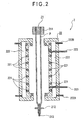
- Fig. 2 is a sectional view of a hollow molding machine used in the molding method relating to the second embodiment of the present invention.
- Hollow molding machine 2 is a machine which produces resin molding having the prescribed shape from resin composition in which fibrous filler (A) and thermoplastic resin (B) are mixed, and has hollow molding machine body 21 and die 22.
- Hollow molding machine body 21 performs melting and kneading of resin composition and extrudes it in the form of parison P in between die 22, and has extrusion dice 211 which converts parison P being extruded into cylindrical form, parison sealing 212 which seals lower end part of parison P, and gas injection pipe 213 which blows a gas into parison P.
- the die 22 works so as to be freely opened or closed, and is used for grasping parison P being extruded by the hollow molding machine body 21, and has a die temperature control pipe 221 for regulating temperature of the die 22, a cooling jacket 222 for cooling of the die 22 and a gas blowing pipe 223 for blowing of air from the die 22 to parison P inside.
- the die temperature control pipe 221 regulates temperature of the die 22 by circulating, for example, steam, heating oil and the like.
- the cooling jacket 222 has a cooling medium inlet 222A being connected to the outside and a cooling medium outlet 222B, a cooling medium is introduced from the outside from the cooling medium inlet 222A and cooling medium outlet 222B for cooling of the die 22.
- the gas blowing pipe 223 works so as to move forward or backward smoothly or from the inside to the outside of the die 22, protruded into the die 22 and stabbed into parison P for blowing a gas into parison P.
- the hollow molding machine 2 is operated, and an extruder (not illustrated) performs melting and kneading of the resin composition and extrudes it.
- an extruder (not illustrated) performs melting and kneading of the resin composition and extrudes it.
- parison P in cylindrical from is extruded from the extrusion dice 211 between one set of mold opened die 22.
- the parison sealing 212 seals lower end part of parison P thus extruded.
- the gas injection pipe 213 is protruded from die surface and is stabbed into parison wall thereby introducing air into parison inside. Parison P then inflates, presses itself against the mold surface and brings itself into intimate contact with mold surface of the die 22 to perform shaping.
- temperature of the die 22 is set by the die temperature control pipe 221 in the range of [the Vicat softening point Tb minus 20°C] of the thermoplastic resin (B) to less than the melting point thereof, for such a case where the thermoplastic resin (B) is crystalline resin, and in the range of [the Vicat softening point Tb minus 20°C] to [the Vicat softening point Tb plus 20°C] of the thermoplastic resin (B), when the thermoplastic resin (B) is non-crystalline resin.
- the temperature is set in the range of [the Vicat softening point Tb minus 10°C] to [melting point minus 10°C] of the thermoplastic resin (B) when the thermoplastic resin (B) is crystalline resin, and in the range of [the Vicat softening point Tb minus 10°C] to [the Vicat softening point plus 10°C] of the thermoplastic resin (B) for such a case where the thermoplastic resin (B) is non-crystalline resin.
- temperature of the die 22 (temperature at holding) is held for the preset time in the range of [crystallization temperature Tc minus 15°C] to [crystallization temperature Tc plus 10°C] of the thermoplastic resin (B) when the thermoplastic resin (B) is crystalline resin, and it is further preferable that the temperature is held for the preset time in the range of [crystallization temperature Tc minus 10°C] to [crystallization temperature Tc].
- the preset time should be held in the range of 10 to 300 sec., preferably in the range of 30 to 200 sec. Although the longer this holing time, the better products are obtained, longer than 300 sec is not desirable since molding cycle becomes longer and the productivity is deteriorated.
- This temperature range and the holding time are determined based on the tolerance of lifting of the fibrous filler of resin molding considering size of and thickness of resin molding, and type of resin, presence of additives and the like comprehensively.
- a cooling medium is circulated through the cooling jacket 222 while the heated medium is being maintained in the die temperature control pipe 221.
- cooling medium at approximately room temperature is introduced in the cooling jacket 222 in order to cool the temperature to such a level where the resin molding can be taken out (temperature at cooling), for example, down to glass transition temperature Tg of the thermoplastic resin (B).
- This cooling rate is in the range which is normally used for hollow molding method.
- the temperature is cooled down to a level which allows taking-out of the resin molding without holding it for the preset time, for such a case where the thermoplastic resin (B) is non-crystalline.
- Resin molding is thus manufactured by the hollow molding method according to processes mentioned above.
- thermoplastic resin (B) materials similar to those used in the first embodiment can be adopted.
- thermoplastic resin (B) is crystalline resin
- crystallization of whole resin molding as well as crystallization on the surface of the resin molding can be controlled which eliminates warpage deformation and improves dimensional accuracy.
- molding is made by hollow molding method according to the second embodiment under molding conditions shown hereafter, and a resin molding with 3 mm thickness at general part was manufactured.
- Amount of fibrous filler (A) added 30 wt% (with regard to resin composition 100 wt%)
- a resin composition in which the fibrous filler (A) and thermoplastic resin (B) were dry blended was molded by the hollow molding method according to the second embodiment.
- a resin molding was manufactured by the same method as used in the embodiment 1 except that the molding conditions (resin composition) in the embodiment 1 were altered as follows: Resin composition; Fibrous filler (A): Glass fiber [Fiber diameter: 16 ⁇ m, Fiber length: 4 mm]
- Amount of fibrous filler (A) added 20 wt% (with regard to resin composition 100 wt%)
- a resin molding was manufactured by the same method as used in the embodiment 2 except that the molding conditions in the embodiment 2 were altered as follows: Die; Molded surface: Embossing used for automobile interior decoration
- Injection molding machine clamping pressure of 850 ton Die; Flat plate [Length: 600 mm, Width: 400 mm, Thickness: 25 mm, Molded surface: Mirror finish less than 0.5S]
- a resin molding was manufactured by the same method as used in the embodiment 2 except that the molding conditions in the embodiment 2 were altered as follows: Die temperature: Temperature at holding: 115°C
- a resin molding was manufactured by the same method as used in the embodiment 2 except that the molding conditions in the embodiment 2 were altered as follows: Die temperature: Temperature at holding: 135°C
- a resin molding was manufactured by the same method as used in the embodiment 1 except that the molding conditions in the embodiment 1 were altered as follows: Resin composition; Thermoplastic resin (B): Shock resistance polystyrene (HIPS, manufactured by Idemitsu Kosan Co., Ltd., HT52). Namely, amorphous thermoplastic resin that is different from those used in the embodiments 1 through 6 was used.
- Thermoplastic resin (B) Shock resistance polystyrene (HIPS, manufactured by Idemitsu Kosan Co., Ltd., HT52). Namely, amorphous thermoplastic resin that is different from those used in the embodiments 1 through 6 was used.
- molding of a resin molding was performed by the same method as used in the embodiment 2 except that the molding conditions in the embodiment 2 were altered as follows: Die temperature; Temperature at holding: 100°C
- the embodiment 8 shaping of a resin composition was performed in the die heated to 130°C and after shaping, it was held in the die heated to 100°C. Cooling was started after holding for the preset time.
- the embodiment 8 was adapted to the temperature range of ([the Vicat softening point minus 20°C] to less than melting point) at shaping according to Claim 1 of the present invention.
- the embodiment 8 is the one in which holding temperature was varied from those in the embodiments 2, 5, and 6, to compare with these embodiments.
- the temperature at holding in the embodiment 8 does not fall into the temperature range ([crystallization temperature minus 15°C] to [crystallization temperature plus 10°C]) according to Claim 3 of the present invention.
- a resin molding was manufactured by the same method as used in the embodiment 2 except that the molding conditions in the embodiment 2 were altered as follows: Die temperature; 80°C (constant)
- a resin molding was manufactured by the same method as used in the comparison example 1 except that the molding conditions in the comparison example 1 were altered as follows: Die; molded surface: Embossing used for automobile interior decoration
- a resin molding was manufactured by the same method as used in the comparison example 1 except that the molding conditions in the comparison example 1 were altered as follows: Die temperature; 160°C (constant)
- a resin molding was manufactured by the same method as used in the embodiment 4 except that the molding conditions in the embodiment 4 were altered as follows: Die temperature; 40°C (constant)
- Fine unevenness on the resin molding surface generated by mirror finished die is measured using a scanning type laser microscope (Olympus Optical Co., Ltd. make LSM-GM).
- this sort of measurement is performed for resin moldings molded by embodiments 1, 2, and 4 through 8, and by comparison examples 1, and 3 through 5.
- a sheet of section paper with 1 mm square is held over the resin molding surface obtained by mirror finished die, and judgment is made whether or not square cells can be clearly visually discriminated from the image reflected on the resin molding.
- Emboss height on the resin molding surface obtained by a die subjected to embossing is measured using a scanning type laser microscope (Olympus Optical Co., Ltd. make LSM-GM). At the same time, emboss depth on the die surface subjected to embossing is measured. Then a ratio expressed by emboss height on the resin molding surface divided by emboss depth on the die surface is calculated.
- Presence of shrinkage on the resin molding surface is evaluated visually. Besides, a resin molding is placed on the flat plane and status of warpage deformation is evaluated visually.
- Tables 1 and 2 show molding conditions and results of evaluation of embodiments 1 through 8, comparison examples 1 through 5.
- Evaluation of embodiment 1 shows that average surface roughness is 2 ⁇ m, image clarity is good, and evaluation of shrinkage and warpage is good (o).
- results obtained are average surface roughness of 3 ⁇ m, good image clarity, and good evaluation (o) for shrinkage and warpage.
- results obtained are die transcription rate of 95% and good evaluation (o) for shrinkage and warpage.
- die transcription rate is less than 90%, average surface roughness of the resin molding exceeds 5 ⁇ m in many cases. Namely, the fibrous filler (A) is exposed at surface of the resin molding in many cases. In the case of the embodiment 3, from the fact die transcription rate is 95%, lifting of the fibrous filler (A) is suppressed and the emboss is transcribed surely resulting in good appearance.
- results obtained are average surface roughness of 2 ⁇ m, good image clarity, and good evaluation (o) for shrinkage and warpage.
- results obtained are average surface roughness of 4 ⁇ m, good image clarity and good evaluation (o) for shrinkage and warpage.
- results obtained are average surface roughness of 2 ⁇ m, good image clarity and good evaluation (o) for shrinkage and warpage.
- results obtained are average surface roughness of 2 ⁇ m, good image clarity and good evaluation (o) for shrinkage and warpage.
- results obtained are average surface roughness of 10 ⁇ m, poor image clarity and good evaluation (o) for shrinkage and warpage.
- the temperature at holding since the temperature at holding is outside the prescription, average surface roughness is more than 5 ⁇ m. However, the temperature at shaping is within the prescription and therefore, comparatively lower average surface roughness (10 ⁇ m) compared to the comparison example 4 is attained. If compared to the embodiment 1 or 6, it is understood that the temperature at holding should preferably be in the range of [crystallization temperature minus 15°C] to [crystallization temperature plus 10°C].
- results are average surface roughness of 40 ⁇ m, poor image clarity and evaluation of shrinkage and warpage is ⁇ .
- results obtained are die transcription rate of 50% and evaluation of shrinkage and warpage is ⁇ .
- results are average surface roughness of 50 ⁇ m, poor image clarity and good evaluation (o) for shrinkage and warpage.
- results obtained are average surface roughness of 30 ⁇ m, poor image clarity and good evaluation (o) for shrinkage and warpage.
- the temperature control mechanism, die temperature control pipe, and cooling jacket described in the embodiments mentioned above to exemplify methods for controlling die temperature do not constitute a limit of the present invention.
- methods for controlling die temperature a method for circulating heating medium in the die, a method for heating electrically such as resistance heating, dielectric heating and the like, a die that incorporates heating method in its body may be adopted.
- a method that heats die surface selectively for gas flame heating from die surface side may be adopted.
- for cooling such a method that circulates a cooling medium in the die may be adopted.
- antioxidant antistatic agent, ultraviolet absorber, light stabilizer, flame retarder, flame-retardant additives, pigment, dispersant, nucleator and the like may be added as necessary to the resin composition.
- the method for molding a resin molding to which fibrous filler (A) is added is not limited to each of the foregoing embodiments.
- vacuum pressure molding and the like may be adopted.
- any molding method is acceptable so long as a die is used.
- the present invention may be used for resin moldings to which fibrous filler is added and molding method thereof, and utilized in automobile and housing facility industries and the like where rigidity and appearance are required.
- the present invention may be used in the automobile industry for instrumental panel parts, door parts, body panel, floor lid, side steps and the like.
- the present invention may be used in the housing facility industry for prefabricated bath parts, assembled furniture, doors, roads, railroad sound-proof walls and the like.
Landscapes
- Engineering & Computer Science (AREA)
- Mechanical Engineering (AREA)
- Manufacturing & Machinery (AREA)
- Moulds For Moulding Plastics Or The Like (AREA)
- Injection Moulding Of Plastics Or The Like (AREA)
- Compositions Of Macromolecular Compounds (AREA)
- Manufacture Of Macromolecular Shaped Articles (AREA)
- Processing And Handling Of Plastics And Other Materials For Molding In General (AREA)
- Casting Or Compression Moulding Of Plastics Or The Like (AREA)
Abstract
Description
or charging the resin composition in molten state into the die for shaping purpose when a temperature of the die is in the range of [the Vicat softening point minus 20°C] to [the Vicat softening point plus 20°C] of the resin (B), when the resin (B) is non-crystalline resin; and
- Die temperature;
- Temperature at shaping: 135°C
Temperature at holding: 125°C
Temperature at cooling: 60°C
Time for blowing: 150 sec.
Resin composition; Fibrous filler (A): GF chopped strand [Fiber diameter: 10µm, Fiber length: 0.5 mm]
Resin composition; Fibrous filler (A): Glass fiber [Fiber diameter: 16µm, Fiber length: 4 mm]
Die; Molded surface: Embossing used for automobile interior decoration
Die; Flat plate [Length: 600 mm, Width: 400 mm, Thickness: 25 mm, Molded surface: Mirror finish less than 0.5S]
Die temperature: Temperature at holding: 115°C
Die temperature: Temperature at holding: 135°C
Resin composition; Thermoplastic resin (B): Shock resistance polystyrene (HIPS, manufactured by Idemitsu Kosan Co., Ltd., HT52). Namely, amorphous thermoplastic resin that is different from those used in the
- Die temperature:
- Temperature at shaping: 130°C
Temperature at cooling: 60°C
Die temperature; Temperature at holding: 100°C
Die temperature; 80°C (constant)
Die; molded surface: Embossing used for automobile interior decoration
Die temperature; 160°C (constant)
Die temperature; 40°C (constant)
Die temperature; Temperature at shaping: 80°C
(Evaluation method)
| Embodiment 1 | Embodiment 2 | Embodiment 3 | Embodiment 4 | Embodiment 5 | Embodiment 6 | Embodiment 7 | ||
| Materials used | Short fiber G F | Continuous fiber G F | ← | ← | ← | ← | Short fiber G F | |
| Crystalline resin | Crystalline resin | ← | ← | ← | ← | Non-crystalline resin | ||
| Fiber length(mm) | 0.5 | 4 | ← | ← | ← | ← | 0.5 | |
| Amount of fiber added (wt%) | 30 | 20 | ← | ← | ← | ← | 30 | |
| Molding method | Hollow molding | ← | ← | Injection molding | Hollow molding | ← | ← | |
| Die temperature | At shaping | 130 | ← | ← | ← | ← | ← | ← |
| At holding | 125 | ← | ← | ← | 115 | 135 | - | |
| At cooling | 60 | ← | ← | ← | ← | ← | ← | |
| Die surface | Mirror finishing | ← | Embossing | Mirror finishing | ← | ← | ← | |
| Average surface roughness (µm) | 2 | 3 | - | 2 | 4 | 2 | 2 | |
| Image clarity | Good | Good | - | Good | Good | Good | Good | |
| Die transcription rate | - | - | 95 | - | - | - | - | |
| Shrinkage and warpage | ○ | ○ | ○ | ○ | ○ | ○ | ○ |
| Comparison example 1 | Comparison example 2 | Comparison example 3 | Comparison example 4 | Comparison example 5 | ||
| Materials used | Short fiber GF | ← | ← | ← | Short fiber GF | |
| Crystalline resin | ← | ← | ← | Non-crystalline resin | ||
| Fiber length(mm) | 4 | ← | ← | ← | 0.5 | |
| Amount of fiber added (wt%) | 20 | ← | ← | ← | 30 | |
| Molding method | Hollow molding | ← | ← | Injection molding | Hollow molding | |
| Die temperature | At shaping | 80 | ← | 160 | 40 | 80 |
| At holding | - | - | - | - | - | |
| At cooling | - | - | - | - | 60 | |
| Die surface | Mirror finishing | Embossing | Mirror finishing | ← | ← | |
| Average surface roughness (µm) | 40 | - | Evaluation impossible due to excessive deformation of resin molding | 2 | 2 | |
| Image clarity | Poor | - | Good | Good | ||
| Die transcription rate | - | 50 | - | - | ||
| Shrinkage and warpage | Δ | Δ | × | ○ | ○ |
For example, surface of the resin molding is rough, anti-scratching feature and high-gloss feature of the resin molding are not satisfactory, or surface of the resin molding is distorted.
Claims (10)
- A molding method for manufacturing a resin molding by charging a resin composition including fibrous filler (A) and resin (B) in molten state into a die by injection, wherein the resin composition contains not less than 7 wt% to less than 30 wt% of the fibrous filler (A) and more than 70 wt% to not exceeding 93 wt% of the resin (B),
and that comprises the steps of;(a) charging the resin composition in molten state into the die for shaping purpose when a temperature of the die is in the range of [the Vicat softening point minus 20°C] of the resin (B) to less than a melting point thereof, when the resin (B) is crystalline resin,
or charging the resin composition in molten state into the die for shaping purpose when a temperature of the die is in the range of [the Vicat softening point minus 20°C] to [the Vicat softening point plus 20°C] of the resin (B), when the resin (B) is non-crystalline resin; and(b) cooling down the die to a temperature which allows taking-out of a molded product, after the shaping is performed. - A molding method for manufacturing a resin molding by extruding a resin composition including fibrous filler (A) and resin (B) to be converted into a molten parison, holding the parison within a die, and by blowing gas into the parison inside, wherein the resin composition contains more than 7 wt% to less than 30 wt% of the fibrous filler (A) and more than 70 wt% to less than 93 wt% of the resin (B),
and that comprises the steps of;(a) blowing gas into the parison inside for shaping purpose when a temperature of the die is in the range of [the Vicat softening point minus 20°C] of the resin (B) to less than a melting point thereof, when the resin (B) is crystalline resin,
or blowing a gas into the parison inside for shaping purpose when a temperature of the die is in the range of [the Vicat softening point minus 20°C] to [the Vicat softening point plus 20°C] of the resin (B), when the resin (B) is non-crystalline resin; and(b) cooling down the die to temperature which allows taking-out of a molded product after the shaping is performed - The molding method according to Claim 1 or Claim 2, wherein if the resin (B) is crystalline resin, after shaping of the resin composition is performed, a temperature of the die is held for preset period in the range of [crystallization temperature minus 15°C] to [crystallization temperature plus 10°C] of the resin (B).
- The molding method according to either of Claims 1 through 3, wherein shaping of the resin composition is performed when a temperature of the die is in the range of [the Vicat softening temperature minus 10°C] of the resin (B) to [melting point minus 10°C], when the resin (B) is crystalline resin,
or performed when a temperature of the die is in the range of [the Vicat softening temperature minus 10°C] to [the Vicat softening temperature plus 10°C] of the resin (B), when the resin (B) is non-crystalline resin. - The molding method according to either of Claims 1 through 4, wherein after shaping of the resin composition is performed, a temperature of the die is held for preset period in the range of [crystallization temperature minus 10°C] to [crystallization temperature] of the resin (B), when the resin (B) is crystalline resin.
- The molding method according to either of Claims 1 through 5, wherein the resin composition contains not less than 10 wt% to not exceeding to 25 wt% of the fibrous filler (A).
- A resin molding manufactured by the molding method according to either of Claims 1 through 6,
- A resin molding containing not less than 7 wt% to less than 30 wt% of a fibrous fiber (A) and more than 70 wt% to not exceeding 93 wt% of a resin (B), wherein surface roughness is less than 5 µm and an image representation of 1 mm square rectangular frame reflected on the surface can be discriminated.
- A resin molding having an emboss on the surface and containing not less than 7 wt% to less than 30 wt% of a fibrous fiber (A) and more than 70 wt% to not exceeding 93 wt% of a resin (B), and is characterized by either one of the following 1 or 2.(1) Die transcription rate is more than 90% for such a case where emboss is provided over whole surface of a resin molding;(2) Die transcription rate is more than 90% and surface roughness of such an area where there is no emboss is less than 5 µm for such a case where emboss is provided in part of a resin molding.
- The resin molding according to Claim 8 or Claim 9, wherein the resin composition contains not less than 10 wt% to not exceeding to 25 wt% of the fibrous filler (A).
Applications Claiming Priority (3)
| Application Number | Priority Date | Filing Date | Title |
|---|---|---|---|
| JP2002294699 | 2002-10-08 | ||
| JP2002294699A JP4266609B2 (en) | 2002-10-08 | 2002-10-08 | Molding method and resin molded body |
| PCT/JP2003/012832 WO2004033184A1 (en) | 2002-10-08 | 2003-10-07 | Molding method and resin moldings |
Publications (2)
| Publication Number | Publication Date |
|---|---|
| EP1555108A1 true EP1555108A1 (en) | 2005-07-20 |
| EP1555108A4 EP1555108A4 (en) | 2007-07-25 |
Family
ID=32089187
Family Applications (1)
| Application Number | Title | Priority Date | Filing Date |
|---|---|---|---|
| EP03751360A Withdrawn EP1555108A4 (en) | 2002-10-08 | 2003-10-07 | MOLDING METHOD AND RESIN MOLDINGS |
Country Status (5)
| Country | Link |
|---|---|
| US (1) | US7638083B2 (en) |
| EP (1) | EP1555108A4 (en) |
| JP (1) | JP4266609B2 (en) |
| CN (1) | CN100475484C (en) |
| WO (1) | WO2004033184A1 (en) |
Families Citing this family (14)
| Publication number | Priority date | Publication date | Assignee | Title |
|---|---|---|---|---|
| JP2005067303A (en) | 2003-08-21 | 2005-03-17 | Idemitsu Kosan Co Ltd | Automotive interior parts |
| JP2006160863A (en) * | 2004-12-07 | 2006-06-22 | Fuji Photo Film Co Ltd | Dope manufacturing apparatus and manufacturing method |
| JP4815822B2 (en) * | 2005-03-03 | 2011-11-16 | 小野産業株式会社 | Method for producing composite thermoplastic resin plated molded article |
| JP2006316106A (en) * | 2005-05-10 | 2006-11-24 | Toyota Motor Corp | Polypropylene resin composition and injection molding method and molded body using the same |
| DE102005053690A1 (en) * | 2005-11-10 | 2007-05-31 | Airbus Deutschland Gmbh | Tool, assembly and method for manufacturing a component, component |
| CN101190552A (en) * | 2006-11-29 | 2008-06-04 | 深圳富泰宏精密工业有限公司 | Mold structure |
| WO2012043794A1 (en) * | 2010-09-30 | 2012-04-05 | 旭化成ケミカルズ株式会社 | Injection-molded object |
| JP5709076B2 (en) * | 2010-11-30 | 2015-04-30 | 株式会社アドユニオン研究所 | Manufacturing method of molded products |
| US20120312750A1 (en) | 2011-06-08 | 2012-12-13 | Chandler Systems, Inc. | Water Softener System and Method |
| JP5868738B2 (en) * | 2012-03-08 | 2016-02-24 | 住友重機械工業株式会社 | Injection molding machine |
| JP5997949B2 (en) * | 2012-06-22 | 2016-09-28 | クミ化成株式会社 | Resin injection molding method |
| CN102825719A (en) * | 2012-09-03 | 2012-12-19 | 深圳Tcl新技术有限公司 | Method for enhancing rigidity and dimensional stability of injection-molded element and surface shell of liquid crystal display television |
| CN104552970B (en) * | 2013-10-25 | 2018-11-30 | 中国石油化工股份有限公司 | A kind of polymer composite fibrous preparation method and its preparation containing ultrafine metal fibers it is polymer composite fibrous |
| CN109071897B (en) * | 2016-05-10 | 2021-06-08 | 普瑞曼聚合物株式会社 | Fiber-reinforced polypropylene-based resin composition and molded article thereof |
Family Cites Families (21)
| Publication number | Priority date | Publication date | Assignee | Title |
|---|---|---|---|---|
| JPS54142266A (en) | 1978-04-28 | 1979-11-06 | Asahi Chem Ind Co Ltd | Molding of synthetic resin article |
| JPS5840504B2 (en) * | 1979-02-15 | 1983-09-06 | 旭化成株式会社 | Injection molding method |
| US4439492A (en) * | 1980-08-11 | 1984-03-27 | Asahi-Dow Limited | Injection molded articles with improved surface characteristics |
| JPS63317444A (en) | 1987-06-19 | 1988-12-26 | Teijin Chem Ltd | Blow molded product |
| US5028461A (en) * | 1988-10-03 | 1991-07-02 | Idemitsu Petrochemical Company Limited | Injection molded container for food |
| JP2547266B2 (en) | 1990-02-02 | 1996-10-23 | ポリプラスチックス株式会社 | Polyarylene sulfide resin composition and method for preparing the same |
| JPH052922U (en) * | 1991-02-14 | 1993-01-19 | 三菱自動車工業株式会社 | Bearing member |
| JPH052922A (en) | 1991-06-25 | 1993-01-08 | Hitachi Cable Ltd | Electric wire insulated with fluorine-containing resilient material |
| CA2122385A1 (en) | 1993-05-07 | 1994-11-08 | Lewis E. Ferguson | Improved thermoplastic resin molding process |
| JPH06328549A (en) | 1993-05-21 | 1994-11-29 | Asahi Chem Ind Co Ltd | New extrusion blow molding method |
| JPH07186175A (en) | 1993-12-27 | 1995-07-25 | Asahi Chem Ind Co Ltd | Injection-molded gear |
| US6048189A (en) | 1995-04-05 | 2000-04-11 | Japan Synthetic Rubber Co., Ltd. | Blow molding apparatus |
| TW340089B (en) | 1996-05-28 | 1998-09-11 | Idemitsu Petrochemical Co | Method and apparatus for manufacturing hollow formed items |
| JP3681218B2 (en) | 1996-06-11 | 2005-08-10 | 三井化学株式会社 | Blow-molded polypropylene composition, blow-molded body thereof and method for molding the blow-molded body |
| JPH1025394A (en) | 1996-07-11 | 1998-01-27 | Japan Synthetic Rubber Co Ltd | Rubber reinforced styrenic resin composition |
| JP3605956B2 (en) * | 1996-08-22 | 2004-12-22 | 東レ株式会社 | Reinforced polyester resin composition and molded article thereof |
| JPH10100156A (en) | 1996-09-30 | 1998-04-21 | Nippon G Ii Plast Kk | Method for obtaining molded product of injection compression molding of thermoplastic resin having high quality appearance |
| JP3958415B2 (en) | 1997-09-29 | 2007-08-15 | 株式会社クレハ | Method for producing polyarylene sulfide molded body |
| JP2000289074A (en) | 1999-04-09 | 2000-10-17 | Polyplastics Co | Manufacturing method of thick molded products |
| JP2001088200A (en) * | 1999-09-21 | 2001-04-03 | Idemitsu Petrochem Co Ltd | Molding method for hollow molded products |
| JP4255045B2 (en) | 2000-10-05 | 2009-04-15 | ポリプラスチックス株式会社 | Manufacturing method of molded products |
-
2002
- 2002-10-08 JP JP2002294699A patent/JP4266609B2/en not_active Expired - Fee Related
-
2003
- 2003-10-07 EP EP03751360A patent/EP1555108A4/en not_active Withdrawn
- 2003-10-07 CN CNB2003801053824A patent/CN100475484C/en not_active Expired - Lifetime
- 2003-10-07 WO PCT/JP2003/012832 patent/WO2004033184A1/en not_active Ceased
- 2003-10-07 US US10/530,713 patent/US7638083B2/en not_active Expired - Lifetime
Also Published As
| Publication number | Publication date |
|---|---|
| CN100475484C (en) | 2009-04-08 |
| US7638083B2 (en) | 2009-12-29 |
| US20060110576A1 (en) | 2006-05-25 |
| EP1555108A4 (en) | 2007-07-25 |
| JP2004130528A (en) | 2004-04-30 |
| CN1723109A (en) | 2006-01-18 |
| JP4266609B2 (en) | 2009-05-20 |
| WO2004033184A1 (en) | 2004-04-22 |
Similar Documents
| Publication | Publication Date | Title |
|---|---|---|
| US7638083B2 (en) | Molding method and resin moldings | |
| US6150026A (en) | Polypropylene-based resin exterior panel and process for producing the same | |
| EP0908292B1 (en) | Method and apparatus for producing a blow molded article | |
| JP5162364B2 (en) | Multilayer molded article manufacturing method and multilayer molded article | |
| KR960007011B1 (en) | Laminated molded article and manufacturing method | |
| JP2003048241A (en) | Injection compression molding apparatus, injection compression molding method, and injection compression molded product by the method | |
| JPWO1997045246A1 (en) | Manufacturing method and manufacturing device for hollow molded products | |
| EP1142689B1 (en) | Molding method for blow molded product | |
| CA2046786C (en) | Multilayer molded article and method for producing the same | |
| CA2535627C (en) | Composite door structure and method of making same, and composite door and method of making same | |
| US20030199637A1 (en) | Thermoplastic olefin composition, process of making the composition, articles formed from the composition, and a method of forming articles therefrom | |
| CN1871115B (en) | Automotive Interior Parts | |
| KR20200067184A (en) | Foamed molded body and method for manufacturing same | |
| JP2001341173A (en) | Method for manufacturing exterior parts for car | |
| JPH11348104A (en) | Manufacture of film-integrated blow molded product, and blow mold | |
| JP6688968B2 (en) | Molding method and molded body | |
| CN111055473A (en) | A kind of EPP skin plasticization reduction molding process | |
| JPH07276456A (en) | Manufacturing method of resin material for machining and manufacturing method of resin processed product | |
| JP3599838B2 (en) | Method for manufacturing multilayer products | |
| TW486420B (en) | Blow molded product and its production method | |
| JPH11314253A (en) | Gas injection mold of thermoplastic resin | |
| JP2000033635A (en) | Manufacture of automotive part | |
| JPWO2000076747A1 (en) | Hollow molded product and manufacturing method thereof |
Legal Events
| Date | Code | Title | Description |
|---|---|---|---|
| PUAI | Public reference made under article 153(3) epc to a published international application that has entered the european phase |
Free format text: ORIGINAL CODE: 0009012 |
|
| 17P | Request for examination filed |
Effective date: 20050427 |
|
| AK | Designated contracting states |
Kind code of ref document: A1 Designated state(s): AT BE BG CH CY CZ DE DK EE ES FI FR GB GR HU IE IT LI LU MC NL PT RO SE SI SK TR |
|
| AX | Request for extension of the european patent |
Extension state: AL LT LV MK |
|
| DAX | Request for extension of the european patent (deleted) | ||
| RAP1 | Party data changed (applicant data changed or rights of an application transferred) |
Owner name: PRIME POLYMER CO., LTD. |
|
| A4 | Supplementary search report drawn up and despatched |
Effective date: 20070621 |
|
| 17Q | First examination report despatched |
Effective date: 20090420 |
|
| STAA | Information on the status of an ep patent application or granted ep patent |
Free format text: STATUS: THE APPLICATION IS DEEMED TO BE WITHDRAWN |
|
| 18D | Application deemed to be withdrawn |
Effective date: 20101130 |