EP1555007A1 - Clip for dividing two liquids - Google Patents
Clip for dividing two liquids Download PDFInfo
- Publication number
- EP1555007A1 EP1555007A1 EP02770238A EP02770238A EP1555007A1 EP 1555007 A1 EP1555007 A1 EP 1555007A1 EP 02770238 A EP02770238 A EP 02770238A EP 02770238 A EP02770238 A EP 02770238A EP 1555007 A1 EP1555007 A1 EP 1555007A1
- Authority
- EP
- European Patent Office
- Prior art keywords
- latching
- clip
- releasing
- clipping
- clip according
- Prior art date
- Legal status (The legal status is an assumption and is not a legal conclusion. Google has not performed a legal analysis and makes no representation as to the accuracy of the status listed.)
- Ceased
Links
Images

Classifications
-
- A—HUMAN NECESSITIES
- A61—MEDICAL OR VETERINARY SCIENCE; HYGIENE
- A61J—CONTAINERS SPECIALLY ADAPTED FOR MEDICAL OR PHARMACEUTICAL PURPOSES; DEVICES OR METHODS SPECIALLY ADAPTED FOR BRINGING PHARMACEUTICAL PRODUCTS INTO PARTICULAR PHYSICAL OR ADMINISTERING FORMS; DEVICES FOR ADMINISTERING FOOD OR MEDICINES ORALLY; BABY COMFORTERS; DEVICES FOR RECEIVING SPITTLE
- A61J1/00—Containers specially adapted for medical or pharmaceutical purposes
- A61J1/14—Details; Accessories therefor
- A61J1/20—Arrangements for transferring or mixing fluids, e.g. from vial to syringe
- A61J1/2093—Containers having several compartments for products to be mixed
-
- A—HUMAN NECESSITIES
- A61—MEDICAL OR VETERINARY SCIENCE; HYGIENE
- A61M—DEVICES FOR INTRODUCING MEDIA INTO, OR ONTO, THE BODY; DEVICES FOR TRANSDUCING BODY MEDIA OR FOR TAKING MEDIA FROM THE BODY; DEVICES FOR PRODUCING OR ENDING SLEEP OR STUPOR
- A61M39/00—Tubes, tube connectors, tube couplings, valves, access sites or the like, specially adapted for medical use
- A61M39/22—Valves or arrangement of valves
- A61M39/28—Clamping means for squeezing flexible tubes, e.g. roller clamps
- A61M39/284—Lever clamps
-
- B—PERFORMING OPERATIONS; TRANSPORTING
- B65—CONVEYING; PACKING; STORING; HANDLING THIN OR FILAMENTARY MATERIAL
- B65D—CONTAINERS FOR STORAGE OR TRANSPORT OF ARTICLES OR MATERIALS, e.g. BAGS, BARRELS, BOTTLES, BOXES, CANS, CARTONS, CRATES, DRUMS, JARS, TANKS, HOPPERS, FORWARDING CONTAINERS; ACCESSORIES, CLOSURES, OR FITTINGS THEREFOR; PACKAGING ELEMENTS; PACKAGES
- B65D81/00—Containers, packaging elements, or packages, for contents presenting particular transport or storage problems, or adapted to be used for non-packaging purposes after removal of contents
- B65D81/32—Containers, packaging elements, or packages, for contents presenting particular transport or storage problems, or adapted to be used for non-packaging purposes after removal of contents for packaging two or more different materials which must be maintained separate prior to use in admixture
- B65D81/3261—Flexible containers having several compartments
- B65D81/3266—Flexible containers having several compartments separated by a common rupturable seal, a clip or other removable fastening device
-
- A—HUMAN NECESSITIES
- A61—MEDICAL OR VETERINARY SCIENCE; HYGIENE
- A61J—CONTAINERS SPECIALLY ADAPTED FOR MEDICAL OR PHARMACEUTICAL PURPOSES; DEVICES OR METHODS SPECIALLY ADAPTED FOR BRINGING PHARMACEUTICAL PRODUCTS INTO PARTICULAR PHYSICAL OR ADMINISTERING FORMS; DEVICES FOR ADMINISTERING FOOD OR MEDICINES ORALLY; BABY COMFORTERS; DEVICES FOR RECEIVING SPITTLE
- A61J1/00—Containers specially adapted for medical or pharmaceutical purposes
- A61J1/14—Details; Accessories therefor
- A61J1/20—Arrangements for transferring or mixing fluids, e.g. from vial to syringe
- A61J1/2003—Accessories used in combination with means for transfer or mixing of fluids, e.g. for activating fluid flow, separating fluids, filtering fluid or venting
- A61J1/202—Separating means
- A61J1/2034—Separating means having separation clips
-
- Y—GENERAL TAGGING OF NEW TECHNOLOGICAL DEVELOPMENTS; GENERAL TAGGING OF CROSS-SECTIONAL TECHNOLOGIES SPANNING OVER SEVERAL SECTIONS OF THE IPC; TECHNICAL SUBJECTS COVERED BY FORMER USPC CROSS-REFERENCE ART COLLECTIONS [XRACs] AND DIGESTS
- Y10—TECHNICAL SUBJECTS COVERED BY FORMER USPC
- Y10T—TECHNICAL SUBJECTS COVERED BY FORMER US CLASSIFICATION
- Y10T24/00—Buckles, buttons, clasps, etc.
- Y10T24/15—Bag fasteners
-
- Y—GENERAL TAGGING OF NEW TECHNOLOGICAL DEVELOPMENTS; GENERAL TAGGING OF CROSS-SECTIONAL TECHNOLOGIES SPANNING OVER SEVERAL SECTIONS OF THE IPC; TECHNICAL SUBJECTS COVERED BY FORMER USPC CROSS-REFERENCE ART COLLECTIONS [XRACs] AND DIGESTS
- Y10—TECHNICAL SUBJECTS COVERED BY FORMER USPC
- Y10T—TECHNICAL SUBJECTS COVERED BY FORMER US CLASSIFICATION
- Y10T24/00—Buckles, buttons, clasps, etc.
- Y10T24/44—Clasp, clip, support-clamp, or required component thereof
- Y10T24/44641—Clasp, clip, support-clamp, or required component thereof having gripping member formed from, biased by, or mounted on resilient member
- Y10T24/44744—Clasp, clip, support-clamp, or required component thereof having gripping member formed from, biased by, or mounted on resilient member with position locking-means for engaging faces
- Y10T24/44752—Integral locking-means
Definitions
- the present invention relates to a clip for dividing two liquids (hereinafter also referred to as clip, simply) used for blocking a tube, or for blocking or dividing into multiple compartments an opening of a flexible hollow member such as a bag-like article.
- a bag for medical or pharmaceutical use such as an infusion solution bag and the like can be exemplified, but it is not limited for medical or pharmaceutical use, and it can be used in fields where it is necessary to block a flexible hollowmember or form an independent space therein with the clip.
- This clip is used for subdividing solution chambers in bags for medical or pharmaceutical use that are used as infusion solution bags or dialysate bags and the like, disclosed in Utility Model Publication No. 5-8998.
- This clip has a construction wherein catching parts fixing each other are provided to each of both end parts of two clip pieces formed separately, and a linear holding part that clips both sides of the infusion solution bag in the central longitudinal direction excluding the prescribed area at both ends of each clip piece, is formed.
- a clamp that clips a tube or a bag to seal the inner space of the clipped object in a liquid tight condition, disclosed in Japanese Patent Publication No. 4-193179. It is composed of the following: a catching means located at an end of the clamp, binding two plate-like members in a detachable way; a clipping part composed of two plate-like members having pressing projecting parts being parallel to each other, in the longitudinal direction of its inner surface; a detachable latching means maintaining said clipping part in a condition that the clipped object is clipped; and a grasping part located at the other end of the clamp, to give a force to said clipping part for clipping said clipped object by grasping with the finger and the like.
- a clamp that clips a tube or a bag to seal the inner space of the clipped object in a liquid tight condition, disclosed in Japanese Laid-Open Patent Application No. 2000-229648.
- This is a clip that clips the prescribed part of the clipped object from both sides, binding a pair of pinching levers by the axis in a detachable and oscillating way at one end of the clip.
- the other end part of both pinching levers is composed so that it is able to fix and latch by a latching means.
- An insertion channel is formed along the longitudinal direction of the pinching lever in the facing surface from the second pinching lever to the first pinching lever.
- An insertion line section which is abutting to the side wall part by being inserted to this insertion channel, is projectingly formed to the facing surface from the first pinching lever to the second pinching lever. It has a construction that a film material to be clipped is pressure-bonded between the insertion channel of the second pinching lever and the insertion line section of the first pinching lever inserted into the insertion channel.
- a film material to be clipped is pressure-bonded between the insertion channel of the second pinching lever and the insertion line section of the first pinching lever inserted into the insertion channel.
- the clip comprising a clipping means wherein two rims are facing each other by the hinge binding, and a locking element provided at a free end of the rim, the rim comprises a leg being able to press resiliently to the side facing to the rim; and rim 2 provides a channel having a wide opening that can accept said leg together with the object to be clipped, and a taper inner wall surface that leads leg 3 to the narrow back part.
- clips for clipping an object to be clipped such as a tube or a flexible hollow member, for example, a bag-like article
- various kinds of clips are publicly announced.
- the clip for a bag-like article for example, a plastic bag
- type A excels in an airtight function, but it has a problem with easiness of production and opening.
- type B excels in easiness of production, opening and handling, but it has a difficulty in ensuring an airtight function.
- An object of the present invention is to provide a clip for dividing two liquids that solves the aforementioned problem.
- latching releasing force In case of conventional clips wherein an external force from an external direction is added to a clipping arm when releasing the latching of clips, the direction of the force (hereinafter also referred to as latching releasing force) is the same as that of an external impactive force such as falling, therefore, the latching of clips is released when falling, etc.
- the present inventors have solved this problem by finding that a clip that solves the aforementioned problem, which is, "a clip difficult to come off by the impact caused by falling, etc., and easy to be removed by users when used", can be provided by making a structure of the latching means of the clips capable of releasing the latching by adding an external force the latching arm to the external direction (therefore, by adding an external force from the external direction to the clipping arm, the clips are closed), and that as such structure, a structure that has a supporting point part acting the latching releasing force added to the latching means to the direction to release the latching of the latching part can be used.
- the present inventors have thus reached the present invention.
- the present invention comprises a clip comprising opposed clipping arms capable of forming an independent and separate space by pressing and holding therebetween a clipped object constituted of a flexible hollow member, and a latching means, disposed on one end of the opposed clipping arm, which has a latching part capable of latching the clipping arms which are pressing and holding the clipped object between the opposed clipping arms, wherein the clip has a latching releasing means capable of releasing the latching by an external force headed to an external direction from the clipping arm (hereinafter also referred to as latching releasing force), and a structure of the latching means has a supporting point part acting the latching releasing force, added to the latching means by the latching releasing means, to the direction to release the latching of the latching part.
- the latching means is disposed at one or both ends of the clipping arm, and an example of the external force headed to the external direction from the clipping arm includes a force headed to the direction of the arrow shown in Fig. 1.
- the present inventors have found that in order to solve the aforementioned technical problem, it is further effective to dispose the latching part of the latching means at the latching releasing means side of the supporting point part in the clip mentioned above.
- the present invention comprises a clip wherein the latching part of the latching means is disposed at the latching releasing means side of the supporting point part.
- the present inventors have found that in order to solve the aforementioned technical problem, the clip wherein the latching part of the latching means is constituted of a male member and a female member, and one of the male member and the female member is formed on a tip end of an elastic piece capable of oscillating with the use of the supporting point part as a fulcrum, by the latching releasing means (formed on one tip end of the clipping arm), and the other of the male member and the female member is formed on the other tip end of the clipping arm, in each clip mentioned above, is effective.
- the clip of the present invention comprises the clip wherein the latching means is constituted of the latching part having a male member and a female member, and of an elastic piece formed on one tip end of the clipping arm and capable of oscillating with the use of the supporting point part as a fulcrum by the latching releasing means; one of the male member and the female member is formed on a tip end of the elastic piece; and the other of the male member and the female member is formed on the other tip end of the clipping arm, in each clip mentioned above.
- This clip is capable of releasing the latching of the latching part by oscillating the elastic piece with the use of the supporting point part as a fulcrum by the latching releasing means.
- a clip wherein the latching releasing means and the latching means, or the latching releasing means, the latching means and the clipping arm are integrally molded is preferable.
- Examples of the latching releasing means include those comprised of a band shape elastic piece whose tip end is bound to the elastic piece of the latching means, those comprised of a pull-tab integrally molded with the band shape elastic piece bound to the elastic piece of the latching means, or those comprised of the band shape elastic piece bound to the elastic piece of the latching means and a thread-like article bound to the band shape elastic piece.
- the clip of the present invention has is a structure wherein the other end of the clipping arm on which the latching means is formed is bound by an axis in an oscillating way, or by a hinge integrally molded with the clipping arm and formed on the other end, opposite the side the latching means is formed, in an oscillating way.
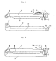
- Fig. 1 describes the constitution of the clipping arm, the latching means and the latching releasing means of the clip of the present invention.
- Fig. 2 describes the constitution of the clipping arm, the latching means and the latching releasing means in another aspect (a thread-like article as a latching releasing means) of the clip of the present invention.
- Fig. 3 is an enlarged view showing the vicinity of the latching means and the latching releasing means of the clip of the present invention.
- POM polyoxymethylene resin
- PP resin polypropylene resin
- PC resin polycarbonate resin
- GF glass fiber
- CF carbon fiber
- POM + GF or POM + CF examples of combination of these resins and reinforcers include, GF- or CF-containing POM (hereinafter referred to as POM + GF or POM + CF), GF- or CF- containing PP (hereinafter referred to as PP + GF or PP + CF) or GF- or CF-containing PC (hereinafter referred to as PC + GF or PC + CF), however, from the viewpoint of the aforementioned balance between the characteristics of the hinge and the rigidity required to ensure the airtight condition of the tube or the flexible hollow member, POM + GF is particularly preferable.
- the opposed clipping arms 5, 10 may have a structure wherein they are bound to a free end without a latching means by axis (6, 7) in an oscillating way as shown in Fig. 2, or as another aspect, like the first invention, a structure wherein they are bound by a hinge integrally molded with the clipping arms and formed on a free end without a latching means, in an oscillating way (not shown), or a structure wherein a means for binding by axis (6, 7), or for binding the clipping arms such as a hinge is not particularly disposed, and each of the clipping arms 5, 10 has on its both ends the latching means, which is one of major characteristics of the present invention as mentioned above, enabling each of the clipping arms 5, 10 to latch each other.
- the clipping arms 5, 10 may have a structure having an insertion channel 9 into which an insertion ridge section 8 mentioned below can be inserted along the longitudinal direction of the clipping arm in the facing surface from one opposed clipping arm 10 to the other clipping arm 5, or a structure having the insertion ridge section 8 to be inserted into the insertion channel 9 in the facing surface from the other clipping arm 5 mentioned above to one opposed clipping arm 10 mentioned above.
- known techniques described in the section of Background Art for instance, the structure described in Japanese Patent Publication No. 2-60580, is exemplified.
- the latching means is constituted of, at least, a latching part and a supporting point part acting the latching releasing force, added by the latching releasing means mentioned below, to the direction to release the latching of the latching part, and has a structure capable of releasing the latching of the latching means by the latching releasing means mentioned below.
- An example of the latching means includes, as shown in Figs. 1 and 2, the latching means having a structure wherein;
- a concave shape such as a recess can be used instead of the through hole 15.
- this latching means can make the clip of the present invention clip an object to be clipped by adding an external force to the opposite side of A shown in Fig. 1, in other words, inside the clipping arms 5, 10.
- the latching means is integrally molded with the clipping arm, and that the resins suitable to form the clipping arm mentioned above are adopted as a resin to form the latching means and the clipping arm.
- the latching releasing means is integrally molded with the clipping arm, and that the resins suitable to form the clipping arm mentioned above are adopted as a resin to form the latching means and the clipping arm.
- the latching releasing means binds to the latching means, transmits a latching releasing force to the latching means, and via the supporting point part 3, fulfills its function to release the latching of the hook-like male member 2 and the female member 11 of the latching part.
- a material to constitute the latching releasing means a material hard to transmit an external impactive force to the latching part is preferable.
- a flexible material is preferable because a material which transmits easily a force caused by a releasing operation to the latching part is preferable.
- the followings are exemplified:
- the latching of the hook-like male member 2 and the female member 11 can be released when users add a force to the latching releasing means to the direction A shown in Fig. 1, in other words, the direction toward the outside of the clipping arms 5, 10, and on the contrary, when the clip falls, the latching is safe because it is not released by an external impactive force the clip receives, headed to the direction A shown in Fig. 1, in other words, the direction toward the inside of the clipping arms 5, 10.
- the clip shown in Fig. 1 uses a pull-tab as a latching releasing means
- the clip shown in Fig. 2 uses a thread-like article as a latching means.
- the latching of the clip can be released with less force, and the latching becomes safer for the external impactive force headed to the direction toward the inside of the clipping arms 5, 10.
- the clipping arm, the latching means of the clipping arm, and the latching releasing means for releasing the latching means are integrally molded in the clip of the present invention except when the thread-like article is used as the latching releasing means, however, a clip which is not integrally molded can be also used.
- the thread-like article 13 or loops made of the thread-like article such as "rubber band", used as a member which constitutes the latching releasing means or a member for the latching releasing means in the clip of the present invention, can exert outstanding effect in the point that it is hard to transmit an external impactive force to a latching part.
- a ring 14 which looks like a pull-tab, may be bound to the thread-like article 13 on the side to which the latching releasing force is added.
- the clip of the present invention is useful as a clip in the fields wherein it is necessary to block a flexible hollow member, for example, bags for medical or pharmaceutical use such as infusion solution bags, and to form an independent space therein.
- the clip exerts an outstanding effect as follows; the clipping can be maintained when an external impact force such as those caused by falling is added, therefore, it is safe, while users can release the latching of the clip with less force when using the clip.
Landscapes
- Health & Medical Sciences (AREA)
- Veterinary Medicine (AREA)
- Public Health (AREA)
- Engineering & Computer Science (AREA)
- Life Sciences & Earth Sciences (AREA)
- Animal Behavior & Ethology (AREA)
- General Health & Medical Sciences (AREA)
- Heart & Thoracic Surgery (AREA)
- Pulmonology (AREA)
- Mechanical Engineering (AREA)
- Pharmacology & Pharmacy (AREA)
- Anesthesiology (AREA)
- Biomedical Technology (AREA)
- Hematology (AREA)
- Clamps And Clips (AREA)
- Bag Frames (AREA)
- Infusion, Injection, And Reservoir Apparatuses (AREA)
Abstract
The present invention relates to a type B clip which solves
a technical problem that the latching of the clip is not easily
released by the external force caused by falling, etc., and is
easily released when the clip is used by users.
The clip comprises opposed clipping arms capable of forming
an independent and separate space by pressing and holding a
clipped object constituted of a flexible hollow member
therebetween, and a latching means, disposed on one end of the
opposed clipping arm, which has a latching part capable of
latching the clipping arms which are pressing and holding the
clipped object therebetween, wherein the clip has a latching
releasing means capable of releasing the latching by an external
force headed to an external direction from the clipping arm,
and a structure of the latching means has a supporting point
part acting the latching releasing force, added to the latching
means by the latching releasing means , to the direction to release
the latching of the latching part.
Description
The present invention relates to a clip for dividing two
liquids (hereinafter also referred to as clip, simply) used for
blocking a tube, or for blocking or dividing into multiple
compartments an opening of a flexible hollow member such as a
bag-like article.
As for said bag-like article, a bag for medical or
pharmaceutical use such as an infusion solution bag and the like
can be exemplified, but it is not limited for medical or
pharmaceutical use, and it can be used in fields where it is
necessary to block a flexible hollowmember or form an independent
space therein with the clip.
There is a clip that is used for subdividing solution
chambers in bags for medical or pharmaceutical use that are used
as infusion solution bags or dialysate bags and the like,
disclosed in Utility Model Publication No. 5-8998. This clip
has a construction wherein catching parts fixing each other are
provided to each of both end parts of two clip pieces formed
separately, and a linear holding part that clips both sides of
the infusion solution bag in the central longitudinal direction
excluding the prescribed area at both ends of each clip piece,
is formed.
Moreover, there is a clamp that clips a tube or a bag to
seal the inner space of the clipped object in a liquid tight
condition, disclosed in Japanese Patent Publication No. 4-193179.
It is composed of the following: a catching means located at
an end of the clamp, binding two plate-like members in a detachable
way; a clipping part composed of two plate-like members having
pressing projecting parts being parallel to each other, in the
longitudinal direction of its inner surface; a detachable
latching means maintaining said clipping part in a condition
that the clipped object is clipped; and a grasping part located
at the other end of the clamp, to give a force to said clipping
part for clipping said clipped object by grasping with the finger
and the like.
There is a clamp that clips a tube or a bag to seal the
inner space of the clipped object in a liquid tight condition,
disclosed in Japanese Laid-Open Patent Application No.
2000-229648. This is a clip that clips the prescribed part of
the clipped object from both sides, binding a pair of pinching
levers by the axis in a detachable and oscillating way at one
end of the clip. The other end part of both pinching levers
is composed so that it is able to fix and latch by a latching
means. An insertion channel is formed along the longitudinal
direction of the pinching lever in the facing surface from the
second pinching lever to the first pinching lever. An insertion
line section, which is abutting to the side wall part by being
inserted to this insertion channel, is projectingly formed to
the facing surface from the first pinching lever to the second
pinching lever. It has a construction that a film material to
be clipped is pressure-bonded between the insertion channel of
the second pinching lever and the insertion line section of the
first pinching lever inserted into the insertion channel. As
for the clamp sealing the opening of the bag and the like, there
is one disclosed in Japanese Patent Publication No. 2-60580.
As for the clip comprising a clipping means wherein two rims
are facing each other by the hinge binding, and a locking element
provided at a free end of the rim, the rim comprises a leg being
able to press resiliently to the side facing to the rim; and
rim 2 provides a channel having a wide opening that can accept
said leg together with the object to be clipped, and a taper
inner wall surface that leads leg 3 to the narrow back part.
As described above, as for clips for clipping an object
to be clipped, such as a tube or a flexible hollow member, for
example, a bag-like article, various kinds of clips are publicly
announced.
As for the aforementioned clip, in particular, the clip
for a bag-like article, for example, a plastic bag, there are
two types of clips: one is clips that have the latching means
and the part to be pressed integrally (hereinafter referred to
as type A), the other is clips that have the latching means in
a place different from the part to be pressed (hereinafter
referred to as type B). Type A excels in an airtight function,
but it has a problem with easiness of production and opening.
On the other hand, type B excels in easiness of production, opening
and handling, but it has a difficulty in ensuring an airtight
function.
In case of clips of type B, as the latching means have
to be reinforced to ensure the airtight function when the clips
are elongated to the longitudinal direction, the handling will
worsen, for example, significant force will be required to open
and close the clips. When trying to improve the handling, the
clips will come off too easily by the impact caused by falling,
etc., added to a part to be handled. In other words, there is
a problem in the clips of type B that a contradictory technical
problem, which is, "a clip difficult to come off by the impact
caused by falling, etc., and easy to be removed by users when
used", has to be solved. It has been difficult for the person
skilled in the art to solve this problem.
An object of the present invention is to provide a clip
for dividing two liquids that solves the aforementioned problem.
In case of conventional clips wherein an external force
from an external direction is added to a clipping arm when
releasing the latching of clips, the direction of the force
(hereinafter also referred to as latching releasing force) is
the same as that of an external impactive force such as falling,
therefore, the latching of clips is released when falling, etc.
The present inventors have solved this problem by finding that
a clip that solves the aforementioned problem, which is, "a clip
difficult to come off by the impact caused by falling, etc.,
and easy to be removed by users when used", can be provided by
making a structure of the latching means of the clips capable
of releasing the latching by adding an external force the latching
arm to the external direction (therefore, by adding an external
force from the external direction to the clipping arm, the clips
are closed), and that as such structure, a structure that has
a supporting point part acting the latching releasing force added
to the latching means to the direction to release the latching
of the latching part can be used. The present inventors have
thus reached the present invention.
The present invention comprises a clip comprising opposed
clipping arms capable of forming an independent and separate
space by pressing and holding therebetween a clipped object
constituted of a flexible hollow member, and a latching means,
disposed on one end of the opposed clipping arm, which has a
latching part capable of latching the clipping arms which are
pressing and holding the clipped object between the opposed
clipping arms, wherein the clip has a latching releasing means
capable of releasing the latching by an external force headed
to an external direction from the clipping arm (hereinafter also
referred to as latching releasing force), and a structure of
the latching means has a supporting point part acting the latching
releasing force, added to the latching means by the latching
releasing means, to the direction to release the latching of
the latching part.
The latching means is disposed at one or both ends of the
clipping arm, and an example of the external force headed to
the external direction from the clipping arm includes a force
headed to the direction of the arrow shown in Fig. 1.
In addition, the present inventors have found that in order
to solve the aforementioned technical problem, it is further
effective to dispose the latching part of the latching means
at the latching releasing means side of the supporting point
part in the clip mentioned above. In other words, the present
invention comprises a clip wherein the latching part of the
latching means is disposed at the latching releasing means side
of the supporting point part. By adopting this structure, the
latching means can be released very easily also by the latching
releasing force headed to the external direction from the
clipping arm, and the latching is maintained more safely against
the force headed from the external direction to the direction
of the clipping arm, such as external impactive force.
Further, the present inventors have found that in order
to solve the aforementioned technical problem, the clip wherein
the latching part of the latching means is constituted of a male
member and a female member, and one of the male member and the
female member is formed on a tip end of an elastic piece capable
of oscillating with the use of the supporting point part as a
fulcrum, by the latching releasing means (formed on one tip end
of the clipping arm), and the other of the male member and the
female member is formed on the other tip end of the clipping
arm, in each clip mentioned above, is effective. In other words,
the clip of the present invention comprises the clip wherein
the latching means is constituted of the latching part having
a male member and a female member, and of an elastic piece formed
on one tip end of the clipping arm and capable of oscillating
with the use of the supporting point part as a fulcrum by the
latching releasing means; one of the male member and the female
member is formed on a tip end of the elastic piece; and the other
of the male member and the female member is formed on the other
tip end of the clipping arm, in each clip mentioned above. This
clip is capable of releasing the latching of the latching part
by oscillating the elastic piece with the use of the supporting
point part as a fulcrum by the latching releasing means.
As for the clip of the present invention, a clip wherein
the latching releasing means and the latching means, or the
latching releasing means, the latching means and the clipping
arm are integrally molded is preferable.
Examples of the latching releasing means include those
comprised of a band shape elastic piece whose tip end is bound
to the elastic piece of the latching means, those comprised of
a pull-tab integrally molded with the band shape elastic piece
bound to the elastic piece of the latching means, or those
comprised of the band shape elastic piece bound to the elastic
piece of the latching means and a thread-like article bound to
the band shape elastic piece.
The clip of the present invention has is a structure wherein
the other end of the clipping arm on which the latching means
is formed is bound by an axis in an oscillating way, or by a
hinge integrally molded with the clipping arm and formed on the
other end, opposite the side the latching means is formed, in
an oscillating way.
Fig. 1 describes the constitution of the clipping arm,
the latching means and the latching releasing means of the clip
of the present invention. Fig. 2 describes the constitution
of the clipping arm, the latching means and the latching releasing
means in another aspect (a thread-like article as a latching
releasing means) of the clip of the present invention. Fig.
3 is an enlarged view showing the vicinity of the latching means
and the latching releasing means of the clip of the present
invention.
There is no particular limitation to types of synthetic
resins constituting the opposed clipping arms, 5, 10 shown in
Figs. 1 and 2, which constitute the clip of the present invention,
however, for the balance between the characteristics of the hinge
required by the clip of the present invention, and the rigidity
required to ensure the airtight condition of the tube or the
flexible hollow member, it is preferable to be made with
polyoxymethylene resin (hereinafter referred to as POM),
polypropylene resin (hereinafter referred to as PP resin),
polycarbonate resin (hereinafter referred to as PC resin), or
to be made by mixing reinforcer such as glass fiber (hereinafter
referred to as GF), carbon fiber (hereinafter referred to as
CF) and the like to said resin.
Examples of combination of these resins and reinforcers
include, GF- or CF-containing POM (hereinafter referred to as
POM + GF or POM + CF), GF- or CF- containing PP (hereinafter referred
to as PP + GF or PP + CF) or GF- or CF-containing PC (hereinafter
referred to as PC + GF or PC + CF), however, from the viewpoint
of the aforementioned balance between the characteristics of
the hinge and the rigidity required to ensure the airtight
condition of the tube or the flexible hollow member, POM + GF
is particularly preferable.
The opposed clipping arms 5, 10 may have a structure wherein
they are bound to a free end without a latching means by axis
(6, 7) in an oscillating way as shown in Fig. 2, or as another
aspect, like the first invention, a structure wherein they are
bound by a hinge integrally molded with the clipping arms and
formed on a free end without a latching means, in an oscillating
way (not shown), or a structure wherein a means for binding by
axis (6, 7), or for binding the clipping arms such as a hinge
is not particularly disposed, and each of the clipping arms 5,
10 has on its both ends the latching means, which is one of major
characteristics of the present invention as mentioned above,
enabling each of the clipping arms 5, 10 to latch each other.
The clipping arms 5, 10 may have a structure having an
insertion channel 9 into which an insertion ridge section 8
mentioned below can be inserted along the longitudinal direction
of the clipping arm in the facing surface from one opposed clipping
arm 10 to the other clipping arm 5, or a structure having the
insertion ridge section 8 to be inserted into the insertion
channel 9 in the facing surface from the other clipping arm 5
mentioned above to one opposed clipping arm 10 mentioned above.
As the structure thus described, known techniques described in
the section of Background Art, for instance, the structure
described in Japanese Patent Publication No. 2-60580, is
exemplified.
The latching means is constituted of, at least, a latching
part and a supporting point part acting the latching releasing
force, added by the latching releasing means mentioned below,
to the direction to release the latching of the latching part,
and has a structure capable of releasing the latching of the
latching means by the latching releasing means mentioned below.
An example of the latching means includes, as shown in
Figs. 1 and 2, the latching means having a structure wherein;
A concave shape such as a recess can be used instead of
the through hole 15.
Further, this latching means can make the clip of the
present invention clip an object to be clipped by adding an
external force to the opposite side of A shown in Fig. 1, in
other words, inside the clipping arms 5, 10.
In addition, it is preferable that the latching means is
integrally molded with the clipping arm, and that the resins
suitable to form the clipping arm mentioned above are adopted
as a resin to form the latching means and the clipping arm.
The latching releasing means
The latching releasing means binds to the latching means,
transmits a latching releasing force to the latching means, and
via the supporting point part 3, fulfills its function to release
the latching of the hook-like male member 2 and the female member
11 of the latching part.
Further, as for a material to constitute the latching
releasing means, a material hard to transmit an external
impactive force to the latching part is preferable. A flexible
material is preferable because a material which transmits easily
a force caused by a releasing operation to the latching part
is preferable.
As a constitution of the latching releasing means, for
example, the followings are exemplified:
The latching of the hook-like male member 2 and the female
member 11 can be released when users add a force to the latching
releasing means to the direction A shown in Fig. 1, in other
words, the direction toward the outside of the clipping arms
5, 10, and on the contrary, when the clip falls, the latching
is safe because it is not released by an external impactive force
the clip receives, headed to the direction A shown in Fig. 1,
in other words, the direction toward the inside of the clipping
arms 5, 10.
The clip shown in Fig. 1 uses a pull-tab as a latching
releasing means, and the clip shown in Fig. 2 uses a thread-like
article as a latching means. With the use of the pull-tab and
the thread-like article, the latching of the clip can be released
with less force, and the latching becomes safer for the external
impactive force headed to the direction toward the inside of
the clipping arms 5, 10.
It is preferable in view of production that the clipping
arm, the latching means of the clipping arm, and the latching
releasing means for releasing the latching means are integrally
molded in the clip of the present invention except when the
thread-like article is used as the latching releasing means,
however, a clip which is not integrally molded can be also used.
In addition, the thread-like article 13 or loops made of
the thread-like article such as "rubber band", used as a member
which constitutes the latching releasing means or a member for
the latching releasing means in the clip of the present invention,
can exert outstanding effect in the point that it is hard to
transmit an external impactive force to a latching part.
Further, as shown in Fig. 2, a ring 14, which looks like
a pull-tab, may be bound to the thread-like article 13 on the
side to which the latching releasing force is added.
As described above, the clip of the present invention is
useful as a clip in the fields wherein it is necessary to block
a flexible hollow member, for example, bags for medical or
pharmaceutical use such as infusion solution bags, and to form
an independent space therein. The clip exerts an outstanding
effect as follows; the clipping can be maintained when an external
impact force such as those caused by falling is added, therefore,
it is safe, while users can release the latching of the clip
with less force when using the clip.
Claims (12)
- A clip comprising opposed clipping arms capable of forming an independent, separate space by pressing and holding therebetween a clipped object constituted of a flexible hollow member, and a latching means, disposed on one end of the opposed clipping arm, which has a latching part capable of latching the clipping arms which are pressing and holding the clipped object therebetween, wherein the clip has a latching releasing means capable of releasing the latching by an external force headed to an external direction from the clipping arm (hereinafter also referred to as latching releasing force), and a structure of the latching means has a supporting point part acting the latching releasing force, added to the latching means by the latching releasing means, to the direction to release the latching of the latching part.
- The clip according to claim 1, wherein the latching means is disposed at the both ends of the clipping arm.
- The clip according to claim 1 or 2, wherein the latching part of the latching means is disposed at the latching releasing means side of the supporting point part.
- The clip according to claim 1, 2 or 3, wherein the latching means is constituted of the latching part having a male member and a female member, and of an elastic piece formed on one tip end of the clipping arm and capable of oscillating with the use of the supporting point part as a fulcrum by the latching releasing means; one of the male member and the female member is formed on a tip end of the elastic piece; and the other of the male member and the female member is formed on the other tip end of the clipping arm.
- The clip according to claim 1, 2, 3 or 4, wherein the latching releasing means and the latching means are integrally molded.
- The clip according to claim 5, wherein the latching releasing means, the latching means and the clipping arm are integrally molded.
- The clip according to claim 1, 2, 3, 4, 5 or 6, wherein the latching releasing means is a band shape elastic piece whose tip end is bound to the elastic piece of the latching means.
- The clip according to claim 7, wherein the latching releasing means is comprised of a pull-tab integrally molded with the band shape elastic piece bound to the elastic piece of the latching means.
- The clip according to claim 1, 2, 3, 4, 5, 6 or 7, wherein the latching releasing means is comprised of a thread-like article or a thread-like article bound to the elastic piece of the latching means.
- The clip according to claim 1, 3, 4, 5, 6, 7, 8 or 9, which has a structure wherein the other end of the opposed clipping arm on which the latching means is formed is bound by an axis in an oscillating way.
- The clip according to claim 1, 3, 4, 5, 6, 7, 8 or 9, which has a structure wherein the clipping arm on which the latching means is formed is bound by a hinge integrally molded with the clipping arm and formed on the other end, opposite the side where the latching means is formed, in an oscillating way.
- The clip according to claim 1, 3, 4, 5, 6, 7, 8, 9, 10 or 11, wherein at least the clipping arm is comprised of a resin made by mixing a glass fiber into a polyoxymethylene resin.
Applications Claiming Priority (1)
| Application Number | Priority Date | Filing Date | Title |
|---|---|---|---|
| PCT/JP2002/010980 WO2004037158A1 (en) | 2002-10-23 | 2002-10-23 | Clip for dividing two liquids |
Publications (2)
| Publication Number | Publication Date |
|---|---|
| EP1555007A1 true EP1555007A1 (en) | 2005-07-20 |
| EP1555007A4 EP1555007A4 (en) | 2007-08-15 |
Family
ID=32170772
Family Applications (1)
| Application Number | Title | Priority Date | Filing Date |
|---|---|---|---|
| EP02770238A Ceased EP1555007A4 (en) | 2002-10-23 | 2002-10-23 | Clip for dividing two liquids |
Country Status (6)
| Country | Link |
|---|---|
| US (1) | US7428771B2 (en) |
| EP (1) | EP1555007A4 (en) |
| JP (1) | JPWO2004037158A1 (en) |
| CN (1) | CN1688274A (en) |
| AU (1) | AU2002336290A1 (en) |
| WO (1) | WO2004037158A1 (en) |
Cited By (2)
| Publication number | Priority date | Publication date | Assignee | Title |
|---|---|---|---|---|
| WO2017142598A1 (en) * | 2016-02-17 | 2017-08-24 | Becton, Dickinson And Company | Pinch clamp |
| US11040186B2 (en) | 2015-10-28 | 2021-06-22 | Becton, Dickinson And Company | Pinch clamp device |
Families Citing this family (11)
| Publication number | Priority date | Publication date | Assignee | Title |
|---|---|---|---|---|
| DE202004017855U1 (en) * | 2004-11-17 | 2005-02-17 | Gea Buck Valve Gmbh | Coupling closure for filling and emptying vessels comprises a first closing strip containing an elastic cheek body, a second closing strip, and a first elastic element with opposite-lying ends |
| US20070209951A1 (en) * | 2006-03-13 | 2007-09-13 | Baylor College Of Medicine | Multi-chamber container |
| TWM403459U (en) * | 2010-11-09 | 2011-05-11 | Jing-Tian Pi | Quick-lock clip of automobile seat belt |
| WO2012076690A1 (en) * | 2010-12-10 | 2012-06-14 | Xellia Pharmaceutical Aps | Closure device for infusion solution bags |
| US9427037B1 (en) * | 2013-02-26 | 2016-08-30 | Debra Ann Atherton | Clip for fabric and method of use |
| US9210990B2 (en) * | 2013-09-16 | 2015-12-15 | Matt Hoskins | Multi-chamber fluid containers |
| DE102014005569A1 (en) * | 2014-04-16 | 2015-10-22 | Fresenius Medical Care Deutschland Gmbh | Multi-chamber bag opening aid |
| CN105937530A (en) * | 2016-04-07 | 2016-09-14 | 胡凡 | Multifunctional sealing clamp adopting new principle |
| USD969599S1 (en) * | 2020-02-14 | 2022-11-15 | Mario Brosche | Fastening clip |
| US11930892B2 (en) * | 2022-02-28 | 2024-03-19 | VisumLearn, Inc. | Device for retaining a strap within a tensioning device |
| MX2024002387A (en) * | 2024-02-23 | 2025-09-02 | Bernal Ricardo Alvarado | Baffle for a wing-type trap |
Family Cites Families (20)
| Publication number | Priority date | Publication date | Assignee | Title |
|---|---|---|---|---|
| US2271133A (en) * | 1940-11-27 | 1942-01-27 | Thoresen Einal | Buckle and latch mechanism |
| US3171184A (en) * | 1962-10-30 | 1965-03-02 | Posse Nils Lage Wilhelm | Clamp |
| US4212303A (en) * | 1978-07-17 | 1980-07-15 | Hollister Incorporated | Umbilical cord clamp |
| SE441261B (en) | 1984-03-26 | 1985-09-23 | Jan Ingemar Neslund | PASKLEMMA |
| US5123146A (en) * | 1987-08-14 | 1992-06-23 | Olson Products, Inc. | Bag closure |
| JPH058998Y2 (en) | 1987-09-30 | 1993-03-05 | ||
| US4834096A (en) * | 1987-10-26 | 1989-05-30 | Edward Weck Incorporated | Plastic ligating clips |
| US5079806A (en) * | 1990-08-01 | 1992-01-14 | Lasso L. P. | Pivotal colsure |
| US5050272A (en) * | 1990-10-16 | 1991-09-24 | Anago, Inc. | Closure member for an ice bag |
| US5125133A (en) * | 1991-11-25 | 1992-06-30 | Hollister Incorporated | Ostomy pouch clamp with hinge-supplementing guide blade |
| SE469717B (en) * | 1992-02-20 | 1993-08-30 | Ingemar Naeslund | CLAMP, SPECIAL BEFORE CONNECTING EASTERS |
| US5604959A (en) * | 1995-09-28 | 1997-02-25 | Tecnol Medical Products, Inc. | Ice pack clip |
| JPH105313A (en) * | 1996-06-21 | 1998-01-13 | Material Eng Tech Lab Inc | Wrapping method for medical container |
| US6058572A (en) * | 1997-10-09 | 2000-05-09 | Folkmar; Jan | Clip |
| JP3650704B2 (en) * | 1999-02-12 | 2005-05-25 | 岩谷産業株式会社 | clip |
| US7131169B2 (en) * | 2001-03-22 | 2006-11-07 | Jan Folkmar | Hinged clip with separable jaws |
| JP4110745B2 (en) * | 2001-04-25 | 2008-07-02 | 株式会社ジェイ・エム・エス | clip |
| AU2002335439B2 (en) | 2001-09-28 | 2008-07-31 | Jms Co., Ltd. | Clip |
| US7062822B2 (en) * | 2003-06-16 | 2006-06-20 | Jan Folkmar | Tube clip |
| US7181806B2 (en) * | 2003-12-08 | 2007-02-27 | Jan Folkmar | Adjustable clips |
-
2002
- 2002-10-23 EP EP02770238A patent/EP1555007A4/en not_active Ceased
- 2002-10-23 JP JP2004546370A patent/JPWO2004037158A1/en active Pending
- 2002-10-23 CN CNA028297946A patent/CN1688274A/en active Pending
- 2002-10-23 WO PCT/JP2002/010980 patent/WO2004037158A1/en not_active Ceased
- 2002-10-23 US US10/531,999 patent/US7428771B2/en not_active Expired - Fee Related
- 2002-10-23 AU AU2002336290A patent/AU2002336290A1/en not_active Abandoned
Cited By (6)
| Publication number | Priority date | Publication date | Assignee | Title |
|---|---|---|---|---|
| US11040186B2 (en) | 2015-10-28 | 2021-06-22 | Becton, Dickinson And Company | Pinch clamp device |
| US11724088B2 (en) | 2015-10-28 | 2023-08-15 | Becton, Dickinson And Company | Pinch clamp device |
| WO2017142598A1 (en) * | 2016-02-17 | 2017-08-24 | Becton, Dickinson And Company | Pinch clamp |
| US10589082B2 (en) | 2016-02-17 | 2020-03-17 | Becton, Dickinson And Company | Pinch clamp |
| US11628290B2 (en) | 2016-02-17 | 2023-04-18 | Becton, Dickinson And Company | Pinch clamp |
| US12194269B2 (en) | 2016-02-17 | 2025-01-14 | Becton, Dickinson And Company | Pinch clamp |
Also Published As
| Publication number | Publication date |
|---|---|
| EP1555007A4 (en) | 2007-08-15 |
| CN1688274A (en) | 2005-10-26 |
| AU2002336290A1 (en) | 2004-05-13 |
| JPWO2004037158A1 (en) | 2006-02-23 |
| WO2004037158A1 (en) | 2004-05-06 |
| US20060107502A1 (en) | 2006-05-25 |
| US7428771B2 (en) | 2008-09-30 |
Similar Documents
| Publication | Publication Date | Title |
|---|---|---|
| US7428771B2 (en) | Clip for dividing two liquids | |
| CA1121683A (en) | Umbilical cord clamp | |
| FI69749B (en) | KOPPLING FOER OSTOMIANORDNING | |
| CA2118715C (en) | A dental floss device | |
| JP2009061050A (en) | buckle | |
| CN100363239C (en) | clip | |
| KR100584460B1 (en) | Cord lock and article holding mechanism | |
| JP7250464B2 (en) | Volumetric pump with tube clamp and tube clamp | |
| GB1583027A (en) | Coupling for joining an ostomy bag to a pad | |
| US9396716B2 (en) | Whistle assembly | |
| JP4110745B2 (en) | clip | |
| US20040065702A1 (en) | Garment hanger | |
| CN110268188A (en) | quick connector | |
| JP3134511U (en) | Clamp and medical device | |
| JP2001259030A (en) | Clamps and medical tools | |
| JP3734495B2 (en) | Clamp and medical device | |
| JP3650704B2 (en) | clip | |
| JP4492104B2 (en) | Clips and retort packaging | |
| JP7437604B2 (en) | clamp | |
| JPH0628136Y2 (en) | Clamp | |
| JPH07136262A (en) | Tube clamp | |
| WO2025103833A1 (en) | Device for pinching-off hoses | |
| JP3106530U (en) | Disinfecting cotton storage bag closure | |
| JP2003024454A (en) | Lever lock and infusion set using the lever lock | |
| JPH0530766Y2 (en) |
Legal Events
| Date | Code | Title | Description |
|---|---|---|---|
| PUAI | Public reference made under article 153(3) epc to a published international application that has entered the european phase |
Free format text: ORIGINAL CODE: 0009012 |
|
| 17P | Request for examination filed |
Effective date: 20050513 |
|
| AK | Designated contracting states |
Kind code of ref document: A1 Designated state(s): AT BE BG CH CY CZ DE DK EE ES FI FR GB GR IE IT LI LU MC NL PT SE SK TR |
|
| AX | Request for extension of the european patent |
Extension state: AL LT LV MK RO SI |
|
| DAX | Request for extension of the european patent (deleted) | ||
| A4 | Supplementary search report drawn up and despatched |
Effective date: 20070717 |
|
| 17Q | First examination report despatched |
Effective date: 20071108 |
|
| STAA | Information on the status of an ep patent application or granted ep patent |
Free format text: STATUS: THE APPLICATION HAS BEEN REFUSED |
|
| 18R | Application refused |
Effective date: 20090123 |