EP1554624B1 - Spectacles with reduced higher order imaging errors - Google Patents
Spectacles with reduced higher order imaging errors Download PDFInfo
- Publication number
- EP1554624B1 EP1554624B1 EP03769454A EP03769454A EP1554624B1 EP 1554624 B1 EP1554624 B1 EP 1554624B1 EP 03769454 A EP03769454 A EP 03769454A EP 03769454 A EP03769454 A EP 03769454A EP 1554624 B1 EP1554624 B1 EP 1554624B1
- Authority
- EP
- European Patent Office
- Prior art keywords
- reference point
- spectacle lens
- straight line
- point
- calculating
- Prior art date
- Legal status (The legal status is an assumption and is not a legal conclusion. Google has not performed a legal analysis and makes no representation as to the accuracy of the status listed.)
- Expired - Lifetime
Links
- 238000003384 imaging method Methods 0.000 title abstract description 3
- 230000000750 progressive effect Effects 0.000 claims abstract description 30
- 230000004075 alteration Effects 0.000 claims description 58
- 206010073261 Ovarian theca cell tumour Diseases 0.000 claims description 20
- 210000001747 pupil Anatomy 0.000 claims description 20
- 208000001644 thecoma Diseases 0.000 claims description 20
- 201000009310 astigmatism Diseases 0.000 claims description 17
- 206010010071 Coma Diseases 0.000 claims description 16
- 238000004519 manufacturing process Methods 0.000 claims description 9
- 230000003287 optical effect Effects 0.000 claims description 9
- 238000000034 method Methods 0.000 claims description 7
- 239000011521 glass Substances 0.000 description 14
- 230000000052 comparative effect Effects 0.000 description 8
- 241000087799 Koma Species 0.000 description 5
- 239000002537 cosmetic Substances 0.000 description 3
- 230000004418 eye rotation Effects 0.000 description 2
- 230000001419 dependent effect Effects 0.000 description 1
- 150000001993 dienes Chemical class 0.000 description 1
- 230000000694 effects Effects 0.000 description 1
- 230000005499 meniscus Effects 0.000 description 1
- 208000014733 refractive error Diseases 0.000 description 1
- 230000001953 sensory effect Effects 0.000 description 1
- 239000010454 slate Substances 0.000 description 1
- 210000002023 somite Anatomy 0.000 description 1
- 230000002123 temporal effect Effects 0.000 description 1
Images


Classifications
-
- G—PHYSICS
- G02—OPTICS
- G02C—SPECTACLES; SUNGLASSES OR GOGGLES INSOFAR AS THEY HAVE THE SAME FEATURES AS SPECTACLES; CONTACT LENSES
- G02C7/00—Optical parts
- G02C7/02—Lenses; Lens systems ; Methods of designing lenses
-
- G—PHYSICS
- G02—OPTICS
- G02C—SPECTACLES; SUNGLASSES OR GOGGLES INSOFAR AS THEY HAVE THE SAME FEATURES AS SPECTACLES; CONTACT LENSES
- G02C7/00—Optical parts
- G02C7/02—Lenses; Lens systems ; Methods of designing lenses
- G02C7/06—Lenses; Lens systems ; Methods of designing lenses bifocal; multifocal ; progressive
- G02C7/061—Spectacle lenses with progressively varying focal power
-
- G—PHYSICS
- G02—OPTICS
- G02C—SPECTACLES; SUNGLASSES OR GOGGLES INSOFAR AS THEY HAVE THE SAME FEATURES AS SPECTACLES; CONTACT LENSES
- G02C2202/00—Generic optical aspects applicable to one or more of the subgroups of G02C7/00
- G02C2202/22—Correction of higher order and chromatic aberrations, wave front measurement and calculation
Definitions
- the invention relates to a method for producing a spectacle lens with low aberrations higher order.
- Single-vision lenses have been using aspheric or atoric surfaces for some time.
- the aim is to improve either the cosmetic properties or the optical properties.
- Cosmetic properties are understood to mean thickness, weight and deflection and optical properties are understood to be astigmatism and refractive index.
- single-vision lenses with aspherical or atorical surfaces should improve the cosmetic properties without impairing the optical properties. So far, aberrations of higher order have not been considered.
- single vision lenses with aspherical or atorical surfaces often experience compatibility problems. These could not be reconstructed because the aberrations of the second order (astigmatism and refractive power) were corrected very well. The cause of these problems was the aberrations of higher order, which were not considered in the prior art and which assume significantly higher values than single vision lenses with spherical or toric surfaces (menisciform lenses).
- the eye-side surface can be an aspherical surface for spherical prescription, for toric prescription an atoric surface, whereby the base curve of the progressive surface is 1 dpt to 1.5 dpt "flatter" than in the spherical or toric eye-surface Image errors in the position of use are corrected by the aspherical or atorical surface.
- a progressive spectacle lens which is characterized by having low aberrations of higher order.
- Higher-order aberrations are understood to mean a spherical aberration and / or a coma.
- the aberrations of higher order correspond to those of a single-vision spectacle lens with spherical or toric surfaces.
- both the astigmatism and the refractive power as well as the coma and the spherical aberration are comparable to those of a meniscus-shaped lens.
- the maximum value of the coma is in a rectangle, that is spanned by the centering point, the prism reference point and the near reference point. Furthermore, the quotient of coma and addition is limited.
- the coma increases only in the reference points with the increase of the pupil diameter only slightly. Furthermore, the coma has a smaller slope in the reference points as a function of the pupil diameter than in the points with maximum coma.
- Both the maximum value and the minimum value of the spherical aberration are in a rectangle spanned by the center point, the prism reference point and the near reference point. Furthermore, the spherical aberration, especially at the reference points, increases only slightly with the increase in pupil diameter. Furthermore, the spherical aberration has a lower slope in the reference points as a function of the pupil diameter than in the points with maximum and minimum values.
- the deflection is selected in such a way that the aberrations of the second order, the astigmatism of slanting bundles and refraction errors are corrected as best as possible.
- single-vision lenses with spherical surfaces are designed as meniscus-shaped lenses.
- the deflection is chosen so that the astigmatism slate bundles and the Refraktioinshiel are minimized.
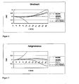
- the aperture error spherical aberration
- FIG. 1 The dotted line above represents the course of a meniscus-shaped lens.
- the solid line represents the shape of an aspherical glass according to the comparative example.
- FIG The fourth dashed line represents the course of an aspherical glass according to the prior art. It can be seen that the meniscus-shaped lens and the two aspherical glasses have very good properties and show at least up to about 20 mm small deviations from the prescribed value. In contrast, the bi-lens has very poor properties.
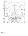
- Fig. 2 The dotted line represents the curve in a meniscus-shaped lens.
- the solid line represents the curve in a spherical glass according to the comparative example and the dotted line represents the curve at a It can be seen that the meniscus-shaped lens and the aspherical glass according to the comparative example have very good properties.
- the prior art has slightly worse properties.
- the bi-lens however, has very poor properties.
- Fig. 3 The dotted line represents the course in a bi-lens.
- the dotted line represents the course in a meniscus-shaped lens
- the solid Line represents the course in an aspheric glass according to the comparative example
- the dashed line represents the curve in an aspherical glass according to the prior art.
- the bi-lens is expected to have very little spherical aberration.
- the prior art has a very high spherical aberration.
- the aspherical spectacle lens according to the comparative example has a small aberration on the order of the meniscus-shaped lens.
- Fig. 4 The dot-dashed line represents the course in a bi-line.
- the dotted lens represents the course in a meniscus-shaped lens.
- the solid line represents the curve in an aspherical glass according to the comparative example and the dashed line represents the curve at a
- the bi-lens has a very small aberration here as well.
- the prior art has a very high aberration.
- the aspherical spectacle lens according to the comparative example has a small aberration on the order of the meniscus-shaped lens.
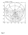
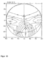
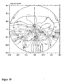
- the coma is represented in Cartesian coordinates for each viewing direction.
- the maximum value is in a rectangle which is vertical from the centering point (top) and the near reference point (bottom) and horizontally from the vertical line passing through the centering point and distance reference point and bounded on the other side by the vertical line passing through the near reference point. Because progression induces coma in a progressive lens, the goal was to construct a progressive lens where the maximum value is the one induced by the refractive power increase itself, otherwise the value should be smaller everywhere. Thus, only the coma is necessary, which is necessary because of the progressive effect, otherwise it should be reduced everywhere.
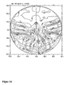
- FIG. 15 shows the maximum values are outside the progression zone and also much higher than in the invention.
- the aim of the invention is therefore to calculate Progressvigläser in which the coma is significantly reduced.
- the maximum value of the coma in the progression zone is located more precisely in a rectangle that is spanned by the centering point, the prism reference point and the near reference point.
- the coma increases with the increase in pupil diameter. However, it is preferred that diene be limited, especially in low-progression frozen glasses.
- Fig. 12 the change in coma is shown as a function of pupil diameter.
- the dashed line with crosses represents the change of the maximum value.
- the solid line with squares represents the change in the far reference point.
- the dotted line with triangles represents the change in the near reference point. It can be seen that the slope (from magnitude) into the Reference points is much lower than the maximum value. In particular, the coma is very low in the reference points and scarcely increases with the increase of the pupil opening.
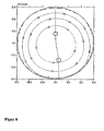
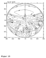
- Fig. 10 is the spherical aberration shown.
- the goal is to allow only so much spherical aberration as is induced by the progressive glass itself. This means that both the maximum and the minimum value are in the progression zone, ie in the rectangle described above.
- the far-range has virtually no spherical aberration.
- Spherical aberration also increases with the increase in pupil diameter. However, it is particularly preferred for progressive glasses with short progression if limited.
- Fig. 11 the change of the spherical aberration is shown as a function of the pupil diameter.
- the dashed line with crosses represents the change of the maximum value.
- the dash-dotted line with crosses represents the change in the minimum value.
- the solid line with squares represents the change in the distance reference point and the dotted line with triangles represents the change in the near reference point. It can be seen that the slope (of magnitude) in the reference points is less than in the maximum values.
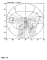
- Fig. 13 and 14 the refractive power and astigmatism (in each case in the position of use) of a progressive lens according to the prior art are shown.
- Fig. 17 to 20 is a further embodiment of the invention shown.
Abstract
Description
Die Erfindung bezieht sich auf ein Verfahren zur Herstellung eines Brillenglases mit geringen Abbildungsfehlern höherer Ordnung.The invention relates to a method for producing a spectacle lens with low aberrations higher order.
Bei Einstärkengläsern werden schon seit längerem asphärische oder atorische Flächen verwendet. Dabei besteht das Ziel darin, entweder die kosmetischen Eigenschaften oder die optischen Eigenschaften zu verbessern. Unter kosmetisehen Eigenschaften versteht man Dicke, Gewicht und Durchbiegung und unter den optischen Eigenschaften versteht man den Astigmatismus und den Brechwert. Im Allgemeinen sollen bei Einstärkengläsern mit asphärischen oder atorischen Flächen die kosmetischen Eigenschaften verbesset werden, ohne dass die optischen Eigenschaften verschlechtert werden. Bisher wurden Abbildungsfehler höherer Ordnung nicht berücksichtigt. Jedoch treten bei Einstärkengläsern mit asphärischen oder atorischen Flächen oftmals Verträglichkeitsprobleme auf. Diese konnten nicht nachvollzogen werden, da die Abbildungsfehler zweiter Ordnung (Astigmatismus und Brechwert) sehr gut korrigiert waren. Die Ursache für diese Probleme lag bei den Abbildungsfehlern höherer Ordnung, welche beim Stand der Technik nicht berücksichtigt wurden und welche deutlich höherrer Werte annehmen als bei Einstärkengläsern mit spährischen oder torischen Flächen (meniskenförmige Linsen).Single-vision lenses have been using aspheric or atoric surfaces for some time. The aim is to improve either the cosmetic properties or the optical properties. Cosmetic properties are understood to mean thickness, weight and deflection and optical properties are understood to be astigmatism and refractive index. In general, single-vision lenses with aspherical or atorical surfaces should improve the cosmetic properties without impairing the optical properties. So far, aberrations of higher order have not been considered. However, single vision lenses with aspherical or atorical surfaces often experience compatibility problems. These could not be reconstructed because the aberrations of the second order (astigmatism and refractive power) were corrected very well. The cause of these problems was the aberrations of higher order, which were not considered in the prior art and which assume significantly higher values than single vision lenses with spherical or toric surfaces (menisciform lenses).
Dokument
Dokument
Bei Progressivgläsern spielen die Abbildungsfehler höherer Ordnung eine ganz wesentliche Rolle, da dort auf Grund der Progression solche Fehler induziert werden. Dennoch wurden im Stand der Technik diese Fehler bisher nicht berücksichtigt.In progressive lenses, the aberrations of higher order play a very important role, because there are induced due to the progression of such errors. Nevertheless, these errors have not been considered in the prior art.
Somit ist festzustellen, daß bei Brillengläser aus dem Stand der Technik bisher keine Abbildungsfehler höherer Ordnung, in erster Linie sphärische Aberration und Koma berücksichtigt wurden.Thus, it has been noted that prior art eyeglass lenses have not yet accounted for higher order aberrations, primarily spherical aberration and coma.
Es ist Aufgabe der Erfindung, ein Verfahren zur Herstellung eines progressiven Brillenglases zur Verfügung zu stellen; sodaß das progressive Brillenglas unter Berücksichtigung der Verträglichkeit für dein Brillenträger bestmöglich optimiert ist.It is an object of the invention to provide a method for producing a progressive spectacle lens available; so that the progressive lens is optimally optimized taking into account the compatibility for your wearer glasses.
Diese Aufgabe wird gelöst durch ein Verfahren zur Herstellung eines progressiven Brillenglases entsprechend den unabhängigen Ansprüchen. Bevorzugte Ausführungsformen ergeben sich aus den Unteransprüchen.This object is achieved by a method for producing a progressive spectacle lens according to the independent claims. Preferred embodiments will be apparent from the dependent claims.
Es wird ein progressives Brillenglas bereitgestellt, welcher dadurch gekennzeichnet ist, daß es geringe Abbildungsfehler höherer Ordnung aufweist. Unter Abbildungsfehlern höherer Ordnung versteht man hierbei eine sphärische Aberration und/oder eine Koma. Bei Einstärkenbrillengläsern die ein Vergleichsbeispeil sind und nicht Gegenstand der Erfindung wird weiter davon ausgegangen, daß die Abbildungsfehler höherer Ordnung denen eines Einstärkenbrillenglases mit sphärischen bzw. torische Flächen entsprechen. Ferner ist sowohl der Astigmatismus und der Brechwert als auch die Koma und die sphärische Aberration vergleichbar mit denen einer meniskenförmigen Linse. Bei den progressiven Brillengläsern (Gegenstand der Erfindung) befindet sich der Maximalwert der Koma in einem Rechteck, das vom Zentrierpunkt, dem Prismenbezugspunkt und dem Nahbezugspunkt aufgespannt wird. Ferner ist der Quotient aus Koma und Addition begrenzt. Die Koma nimmt insbesondere in den Bezugspunkten mit der Zunahme des Pupillendurchmessers nur geringfügig zu. Weiter weist die Koma in den Bezugspunkte als Funktion des Pupillendurchmessers eine geringere Steigung als in den Punkten mit maximaler Koma auf. Sowohl der Maximalwert als auch der Minimalwert der sphärischer Aberration befinden sich in einem Rechteck, das vom Zentrierpunkt, dem Prismenbezugspunkt und dem Nahbezugspunkt aufgespannt wird. Des weiteren nimmt die sphärische Aberration, insbesondere in den Bezugspunkten, mit der Zunahme des Pupillendurchmessers nur geringfügig zu. Weiter weist die sphärische Aberration in den Bezugspunkten als Funktion des Pupillendurchmessers eine geringere Steigung auf als in den Punkten mit Maximal- und Minimalwerten.There is provided a progressive spectacle lens which is characterized by having low aberrations of higher order. Higher-order aberrations are understood to mean a spherical aberration and / or a coma. In the case of single-vision spectacles, which are a comparative example and not the subject of the invention, it is further assumed that the aberrations of higher order correspond to those of a single-vision spectacle lens with spherical or toric surfaces. Further, both the astigmatism and the refractive power as well as the coma and the spherical aberration are comparable to those of a meniscus-shaped lens. In the progressive spectacle lenses (subject of the invention), the maximum value of the coma is in a rectangle, that is spanned by the centering point, the prism reference point and the near reference point. Furthermore, the quotient of coma and addition is limited. The coma increases only in the reference points with the increase of the pupil diameter only slightly. Furthermore, the coma has a smaller slope in the reference points as a function of the pupil diameter than in the points with maximum coma. Both the maximum value and the minimum value of the spherical aberration are in a rectangle spanned by the center point, the prism reference point and the near reference point. Furthermore, the spherical aberration, especially at the reference points, increases only slightly with the increase in pupil diameter. Furthermore, the spherical aberration has a lower slope in the reference points as a function of the pupil diameter than in the points with maximum and minimum values.
Bei sphärischen Einstärkengläsern wird beispielsweise die Durchbiegung so gewählt, daß die Abbildungsfehler zweiter Ordnung, der Astigmatismus schiefer Bündel und Refraktionsfehler bestmöglich korrigiert werden. Aus diesem Grund werden Einstärkengläser mit sphärischen Flächen als meniskenförmige Linsen ausgeführt. Dabei wird die Durchbiegung so gewählt, daß der Astigmatismus schiefer Bündel und der Refraktioinsfehler möglichst gering sind. Um jedoch den Öffnungsfehler (sphärische Aberration) zu korrigieren, sollte man keine meniskenförmigen Linsen, sondern Bi-Linsen (Radianverhältnis ca. 1:6) verwenden. In der Regel treten aber bei meniskenförmigen Linsen keine Verträglichkeitsprobleme auf. Die Ursache liegt anscheinend darin, daß die Aperturblende des Auges relativ klein ist und daß zusätzlich durch den Stiles-Crawford Effekt eine kleinere sensorische Blende der körperlichen Blende überlagert ist. Aus diesem Grund kann davon ausgegangen werden, daß Koma und sphärische Aberration in der Größenordnung wie sie bei meniskenförmigen Linsen auftreten, keine Verträglichkeitsnrobleme hervorrufen.In the case of spherical single-vision lenses, for example, the deflection is selected in such a way that the aberrations of the second order, the astigmatism of slanting bundles and refraction errors are corrected as best as possible. For this reason, single-vision lenses with spherical surfaces are designed as meniscus-shaped lenses. The deflection is chosen so that the astigmatism slate bundles and the Refraktioinsfehler are minimized. However, to correct the aperture error (spherical aberration), one should use no meniscal lenses, but bi-lenses (radian ratio about 1: 6). As a rule, however, compatibility problems do not occur with menisciform lenses on. The cause is apparently that the aperture of the eye is relatively small and that in addition by the Stiles-Crawford effect a smaller sensory aperture of the physical aperture is superimposed. For this reason, it can be assumed that coma and spherical aberration on the order of meniscus lenses do not cause any compatibility problems.
Die Abbildungsfehler höherer Ordnung kann man beispielsweise mit der folgenden Methode berechnen:
- 1. Es wird eine Blickrichtung, ein Objektpunkt, ein Punkt auf der Vorderfläche oder ein Punkt auf der Rückfläche des Brillenglases vorgegeben. Durch eine dieser vier Vorgaben ist zusammen mit dem Augendrehpunkt der Strahlengang eindeutig definiert und mittels Strahldurchrechnung kann man den Hauptstrahl berechnen.
- 2. Die Lage der Aperturblende wird berechnet, indem man die Eintrittspunille des Auges je nach Blickrichtung um den Augendrehpunkt rotieren läßt. Die Mitte der Aperturblende liegt dann auf dem Hauptstrahl. Somit ergibt sich für jede Blickrichtung eine neue Lage der Aperturblende.
- 3. Der Öffnungsstrahlengang wird berechnet, indem von einem gegebenen, auf dem Hauptstrahl liegenden Objektpunkt Strahlen mit unterschiedlichen Öffnungswinkeln berechnet werden.
- 4. Aus diesen Strahlen und den optischen weglängen wird dann die Wellenfront in der Eintrittspupille berechnet.
- 5. Diese Wellenfront stellt man dann mittels "Zernikefunktionen" dar.
- 6. Aus dem Koeffizienten der Zernikefunktion kann man nun die Abbildungsfehler berechnen. So erhält man für jede Blickrichtung unter anderem Astigmatismus, Brechwert, Koma und sphärische Aberration.
- 1. It is given a viewing direction, an object point, a point on the front surface or a point on the rear surface of the lens. By one of these four specifications, the beam path is clearly defined together with the eye rotation point and by means of ray tracing, one can calculate the main ray.
- 2. The position of the aperture diaphragm is calculated by rotating the entrance pillar of the eye around the eye rotation point, depending on the viewing direction. The center of the aperture diaphragm then lies on the main beam. This results in a new position of the aperture diaphragm for each viewing direction.
- 3. The aperture beam path is calculated by calculating beams with different aperture angles from a given object point located on the main beam.
- 4. From these beams and the optical path lengths then the wavefront is calculated in the entrance pupil.
- 5. This wavefront is then represented by "Zernike functions".
- 6. From the coefficient of the Zernike function one can now calculate the aberrations. Astigmatism, refractive power, coma and spherical aberration are thus obtained for each viewing direction.
Die Erfindung wird nachstehend ohne Beschränkung des allgemeinen Erfindungsgedankens anhand von Ausführungsbeispielen unter Bezugnahme auf die Zeichnungen exemplarisch beschrieben, auf die im Übrigen hinsichtlich der Offenbarung aller im Text nicht näher erläuterten erfindungsgemäßen Einzelheiten ausdrücklich verwiesen wird. Es zeigen:
-
Fig. 1 die Veränderung des Brechwertes als Funktion des Abstandes r vom Scheitel (nicht Teil der Erfindung); -
Fig. 2 den Astigmatismus als Funktion des Abstandes r vom Scheitel (nicht Teil der Erfindung); -
Fig. 3 die sphärische Aberration als Funktion des Abstandes r vom Scheitel (nicht Teil der Erfindung); -
Fig. 4 die Koma als Funktion des Abstandes r vom Scheitel (nicht Teil der Erfindung); -
Fig. 5 als Tabelle die Pfeilhöhe einer sphärischen Fläche als Funktion des Abstandes r vom Scheitel (nicht Teil der Erfindung); -
Fig. 6 bis Fig. 8 den Brechwert, den Astigmatismus und die Pfeilhöhen eines Progressivglases nach der Erfindung; -
Fig. 9 die Koma; -
Fig. 10 die sphärische Aberration; -
Fig. 11 die Veränderung der sphärischen Aberration als Funktion des Pupillendurchmessers; -
Fig. 12 die Veränderungen der Koma als Funktion des Pupillendurcrchmessers; -
Fig. 13 und14 den Brechwert und den Astigmatismus eines Progressivglases nach dem Stand der Technik; -
Fig. 15 und16 die Koma und die sphärische Aberration dieses Progressivglases; -
Fig. 17 bis 20 ein weiteres Ausführungsbeispiel nach der Erfindung.
-
Fig. 1 the change in refractive power as a function of the distance r from the vertex (not part of the invention); -
Fig. 2 the astigmatism as a function of the distance r from the vertex (not part of the invention); -
Fig. 3 the spherical aberration as a function of the distance r from the vertex (not part of the invention); -
Fig. 4 the coma as a function of the distance r from the vertex (not part of the invention); -
Fig. 5 as a table, the arrow height of a spherical surface as a function of the distance r from the vertex (not part of the invention); -
Fig. 6 to Fig. 8 the refractive power, the astigmatism and the heights of a progressive lens according to the invention; -
Fig. 9 the coma; -
Fig. 10 the spherical aberration; -
Fig. 11 the change in spherical aberration as a function of pupil diameter; -
Fig. 12 the changes in the coma as a function of the pupil diameter; -
Fig. 13 and14 the refractive power and the astigmatism of a progressive lens according to the prior art; -
Fig. 15 and16 the coma and the spherical aberration of this progressive glass; -
Fig. 17 to 20 a further embodiment of the invention.
In
In
In
In
Bei den
Wie aus
Da die Koma bei der Erfindung durch die Progression (Addition) erzeuge wird, ist es sinnvoll, daß der Quotient aus Koma und Addition begrenzt ist.
Die Koma nimmt mit der Zunahme des Pupillendurchmessers zu. Jedoch ist es bevorzugt, wenn diens begrenzt ist, insbesondere bei Frogressivgläsern mit kurzer Progression.The coma increases with the increase in pupil diameter. However, it is preferred that diene be limited, especially in low-progression frozen glasses.
In
In
Beim Stand der Technik in
Da auch die sphärische Aberration bei der Erfindung nur durch die Progression erzeugt wird, ist es sinnvoll, daß der Quotient aus sphärischer Aberration und Addition begrenzt ist.
Die sphärische Aberration nimmt auch mit der Zunahme des Pupillendurchmessers zu. Jedoch ist es, insbesondere bei Progressivgläseren mit kurzer Progression bevorzugt, wenn dies begrenzt ist.Spherical aberration also increases with the increase in pupil diameter. However, it is particularly preferred for progressive glasses with short progression if limited.
In
Bei den
In den
In den
Claims (6)
- Process for the production of a progressive spectacle lens comprising the steps:• presetting a far reference point, a near reference point and a centring point,• determining a first horizontal straight line that passes through the centring point,• determining a second horizontal straight line that passes through the near reference point,• determining a first vertical straight line that passes through the centring point and the far reference point,• determining a second vertical straight line that passes through the near reference point, and• calculating the progressive spectacle lens, so that the maximum value of the coma lies in a rectangle, which is delimited by the first and second horizontal straight line and by the first and second vertical straight line.
- Process for the production of a progressive spectacle lens according to claim 1, wherein the step of calculating the progressive spectacle lens is performed so that the gradient of the course of the coma in the near and far reference point as a function of the pupil diameter is smaller than the gradient of the course of the maximum coma as a function of the pupil diameter.
- Process for the production of a progressive spectacle lens, comprising the steps:• presetting a far reference point, a near reference point and a centring point,• determining a first horizontal straight line that passes through the centring point,• determining a second horizontal straight line that passes through the near reference point,• determining a first vertical straight line that passes through the centring point and the far reference point,• determining a second vertical straight line that passes through the near reference point, and• calculating the progressive spectacle lens, so that the maximum value and the minimum value of the spherical aberration both lie in a rectangle, which is delimited by the first and second horizontal straight line and by the first and second vertical straight line.
- Process for the production of a progressive spectacle lens according to one of claims 1 to 3, wherein the step of calculating the spectacle lens is performed so that the dependence of the spherical aberration as a function of the pupil diameter in the far reference point and the dependence of the spherical aberration as a function of the pupil diameter in the near reference point respectively have a gradient that is smaller in amount than• the amount of the gradient of the course of the maximum spherical aberration as a function of the pupil diameter, and• the amount of the gradient of the course of the minimum spherical aberration as a function of the pupil diameter.
- Process for the production of a progressive spectacle lens according to one or more of claims 1 to 4, with the following further steps:• presetting a viewing direction or an object point or a point on a front surface or a point on a rear surface of the spectacle lens,• presetting the position of the centre of rotation of the eye,• calculating the optical path by means of ray tracing,• calculating the position of the aperture stop by rotating the entrance pupil of the eye according to the viewing direction around the centre of rotation of the eye, so that the centre of the aperture stop lies on the principal ray,• calculating the aperture optical path, wherein rays with different aperture angles are calculated from a given object point lying on the principal ray,• calculating the wave front in the entrance pupil from these rays and the optical path lengths,• presenting the wave front by means of Zernike functions,• calculating the aberrations from the coefficients of the Zemike function.
- Process for the production of a spectacle lens according to claim 5, wherein in the step of calculating the aberrations the following aberrations are calculated from the coefficients of the Zemike function:• the deviation of the optical power from a desired optical power,• the deviation of the astigmatism from a desired astigmatism,• the spherical aberration and• the coma.
Applications Claiming Priority (3)
| Application Number | Priority Date | Filing Date | Title |
|---|---|---|---|
| DE10250093 | 2002-10-25 | ||
| DE2002150093 DE10250093B4 (en) | 2002-10-25 | 2002-10-25 | Spectacle lens with low aberrations of higher order |
| PCT/EP2003/011859 WO2004038488A1 (en) | 2002-10-25 | 2003-10-24 | Spectacles with reduced higher order imaging errors |
Publications (2)
| Publication Number | Publication Date |
|---|---|
| EP1554624A1 EP1554624A1 (en) | 2005-07-20 |
| EP1554624B1 true EP1554624B1 (en) | 2010-03-03 |
Family
ID=32103090
Family Applications (1)
| Application Number | Title | Priority Date | Filing Date |
|---|---|---|---|
| EP03769454A Expired - Lifetime EP1554624B1 (en) | 2002-10-25 | 2003-10-24 | Spectacles with reduced higher order imaging errors |
Country Status (6)
| Country | Link |
|---|---|
| US (1) | US7063421B2 (en) |
| EP (1) | EP1554624B1 (en) |
| JP (1) | JP2006504127A (en) |
| DE (2) | DE10250093B4 (en) |
| ES (1) | ES2341710T3 (en) |
| WO (1) | WO2004038488A1 (en) |
Families Citing this family (8)
| Publication number | Priority date | Publication date | Assignee | Title |
|---|---|---|---|---|
| US7297735B2 (en) | 2003-03-05 | 2007-11-20 | Eastman Chemical Company | Polycarbonate compositions |
| FR2893151B1 (en) * | 2005-11-08 | 2008-02-08 | Essilor Int | OPHTHALMIC LENS. |
| FR2894038B1 (en) * | 2005-11-29 | 2008-03-07 | Essilor Int | OPHTHALMIC LENS. |
| US8205987B2 (en) | 2010-04-20 | 2012-06-26 | Carl Zeiss Vision Inc. | Method for optimizing a spectacle lens for the wavefront aberrations of an eye and lens |
| DE102010018549B4 (en) | 2010-04-28 | 2022-08-18 | Rodenstock Gmbh | Computer-implemented method for calculating a spectacle lens taking into account the rotation of the eye, device for calculating or optimizing a spectacle lens, computer program product, storage medium, method for manufacturing a spectacle lens, device for manufacturing a spectacle lens and use of a spectacle lens |
| WO2012008975A1 (en) * | 2010-07-16 | 2012-01-19 | Carl Zeiss Vision Inc. | Wavefront optimized progressive lens |
| US9075271B2 (en) * | 2011-09-06 | 2015-07-07 | Japan Display Inc. | Liquid crystal display device |
| WO2018022042A1 (en) | 2016-07-27 | 2018-02-01 | Carl Zeiss Vision International Gmbh | Method for determining an improved design for a progressive lens taking into account higher order aberrations of the eye |
Family Cites Families (10)
| Publication number | Priority date | Publication date | Assignee | Title |
|---|---|---|---|---|
| US5220359A (en) * | 1990-07-24 | 1993-06-15 | Johnson & Johnson Vision Products, Inc. | Lens design method and resulting aspheric lens |
| DE59509463D1 (en) * | 1994-03-30 | 2001-09-06 | Rodenstock Optik G | PROGRESSIVE EYEGLASSES SERIES |
| DE19540186A1 (en) * | 1995-10-28 | 1997-04-30 | Rodenstock Optik G | Single vision glasses with two aspherical surfaces |
| US5835186A (en) * | 1997-02-10 | 1998-11-10 | Copeland; Victor L. | Plano-aspheric spectacle lens |
| FR2772489B1 (en) * | 1997-12-16 | 2000-03-10 | Essilor Int | MULTIFOCAL OPHTHALMIC LENSES WITH VARIABLE SPHERICAL ABERRATION FOLLOWING ADDITION AND AMETROPIA |
| US6183084B1 (en) * | 1998-07-30 | 2001-02-06 | Johnson & Johnson Vision Care, Inc. | Progressive addition lenses |
| DE10020914B4 (en) * | 2000-04-28 | 2020-07-02 | Carl Zeiss Vision Gmbh | Method for calculating a plurality of spectacle lenses from a spectacle lens family and method of manufacturing an spectacle lens from a spectacle lens family |
| US6474814B1 (en) * | 2000-09-08 | 2002-11-05 | Florida Optical Engineering, Inc | Multifocal ophthalmic lens with induced aperture |
| JP2002350785A (en) * | 2001-05-28 | 2002-12-04 | Menicon Co Ltd | Method of designing ocular lens |
| US6712466B2 (en) * | 2001-10-25 | 2004-03-30 | Ophthonix, Inc. | Eyeglass manufacturing method using variable index layer |
-
2002
- 2002-10-25 DE DE2002150093 patent/DE10250093B4/en not_active Expired - Lifetime
-
2003
- 2003-10-24 DE DE50312483T patent/DE50312483D1/en not_active Expired - Lifetime
- 2003-10-24 EP EP03769454A patent/EP1554624B1/en not_active Expired - Lifetime
- 2003-10-24 JP JP2004545997A patent/JP2006504127A/en active Pending
- 2003-10-24 WO PCT/EP2003/011859 patent/WO2004038488A1/en active Application Filing
- 2003-10-24 ES ES03769454T patent/ES2341710T3/en not_active Expired - Lifetime
-
2005
- 2005-04-25 US US11/113,122 patent/US7063421B2/en not_active Expired - Lifetime
Also Published As
| Publication number | Publication date |
|---|---|
| DE10250093B4 (en) | 2015-05-13 |
| EP1554624A1 (en) | 2005-07-20 |
| DE10250093A1 (en) | 2004-05-13 |
| JP2006504127A (en) | 2006-02-02 |
| ES2341710T3 (en) | 2010-06-25 |
| DE50312483D1 (en) | 2010-04-15 |
| US20050206842A1 (en) | 2005-09-22 |
| US7063421B2 (en) | 2006-06-20 |
| WO2004038488A1 (en) | 2004-05-06 |
Similar Documents
| Publication | Publication Date | Title |
|---|---|---|
| EP1277079B1 (en) | Method for calculating a progressive spectacle lens and method for producing a spectacle lens of this type | |
| EP1606668B1 (en) | Method for calculating an individual progressive lens | |
| DE102010007267B4 (en) | Lens element with improved prismatic effect and method for producing a lens element | |
| EP1277080B1 (en) | Method for producing eyeglasses | |
| EP0165950B1 (en) | Multi-intensity spectacle glass with high positive refraction index | |
| EP1554624B1 (en) | Spectacles with reduced higher order imaging errors | |
| EP1656581B1 (en) | Individual single vision spectacles | |
| WO2001081982A2 (en) | Progressive spectacle glass with low rocking effect | |
| EP1488274B1 (en) | Progressive spectacle lens with two non-spherical progressive surfaces | |
| WO2020016378A1 (en) | Progressive spectacle lens with regionally varying refractive index and method for the design of same | |
| EP1939668B1 (en) | Progressive spectacle lens with low magnification differences | |
| DE10191693B4 (en) | Progressive lens with little change in binocular properties during a glance | |
| WO2001081981A2 (en) | Progressive spectacle glass | |
| WO2005040893A1 (en) | Individual spectacle glass | |
| EP1277078B1 (en) | Progressive spectacle lens exhibiting a slight dynamic change of the properties of use during a horizontal viewing movements | |
| EP1277074B1 (en) | Progressive spectacle lens with negligible dynamic distortion | |
| EP3574366A1 (en) | Method for taking into consideration different long-distance and short-distance prismatic corrections | |
| DE10302152B4 (en) | Double progressive spectacle lens | |
| EP3789815A1 (en) | Computer-implemented method for adapting spectacle lens to spectacle frame |
Legal Events
| Date | Code | Title | Description |
|---|---|---|---|
| PUAI | Public reference made under article 153(3) epc to a published international application that has entered the european phase |
Free format text: ORIGINAL CODE: 0009012 |
|
| 17P | Request for examination filed |
Effective date: 20050421 |
|
| AK | Designated contracting states |
Kind code of ref document: A1 Designated state(s): AT BE BG CH CY CZ DE DK EE ES FI FR GB GR HU IE IT LI LU MC NL PT RO SE SI SK TR |
|
| RAP1 | Party data changed (applicant data changed or rights of an application transferred) |
Owner name: RODENSTOCK GMBH |
|
| RBV | Designated contracting states (corrected) |
Designated state(s): DE ES FR GB IT |
|
| 17Q | First examination report despatched |
Effective date: 20061107 |
|
| GRAP | Despatch of communication of intention to grant a patent |
Free format text: ORIGINAL CODE: EPIDOSNIGR1 |
|
| GRAS | Grant fee paid |
Free format text: ORIGINAL CODE: EPIDOSNIGR3 |
|
| GRAA | (expected) grant |
Free format text: ORIGINAL CODE: 0009210 |
|
| AK | Designated contracting states |
Kind code of ref document: B1 Designated state(s): DE ES FR GB IT |
|
| REG | Reference to a national code |
Ref country code: GB Ref legal event code: FG4D Free format text: NOT ENGLISH |
|
| REF | Corresponds to: |
Ref document number: 50312483 Country of ref document: DE Date of ref document: 20100415 Kind code of ref document: P |
|
| REG | Reference to a national code |
Ref country code: ES Ref legal event code: FG2A Ref document number: 2341710 Country of ref document: ES Kind code of ref document: T3 |
|
| PLBE | No opposition filed within time limit |
Free format text: ORIGINAL CODE: 0009261 |
|
| STAA | Information on the status of an ep patent application or granted ep patent |
Free format text: STATUS: NO OPPOSITION FILED WITHIN TIME LIMIT |
|
| 26N | No opposition filed |
Effective date: 20101206 |
|
| REG | Reference to a national code |
Ref country code: GB Ref legal event code: 732E Free format text: REGISTERED BETWEEN 20111013 AND 20111019 |
|
| REG | Reference to a national code |
Ref country code: DE Ref legal event code: R081 Ref document number: 50312483 Country of ref document: DE Owner name: RODENSTOCK GMBH, DE Free format text: FORMER OWNER: RODENSTOCK GMBH, 80469 MUENCHEN, DE Effective date: 20120822 |
|
| REG | Reference to a national code |
Ref country code: FR Ref legal event code: GC Effective date: 20140904 |
|
| REG | Reference to a national code |
Ref country code: FR Ref legal event code: PLFP Year of fee payment: 14 |
|
| REG | Reference to a national code |
Ref country code: FR Ref legal event code: PLFP Year of fee payment: 15 |
|
| REG | Reference to a national code |
Ref country code: FR Ref legal event code: PLFP Year of fee payment: 16 |
|
| PGFP | Annual fee paid to national office [announced via postgrant information from national office to epo] |
Ref country code: FR Payment date: 20221020 Year of fee payment: 20 |
|
| PGFP | Annual fee paid to national office [announced via postgrant information from national office to epo] |
Ref country code: IT Payment date: 20221031 Year of fee payment: 20 Ref country code: GB Payment date: 20221024 Year of fee payment: 20 Ref country code: ES Payment date: 20221118 Year of fee payment: 20 Ref country code: DE Payment date: 20221019 Year of fee payment: 20 |
|
| REG | Reference to a national code |
Ref country code: DE Ref legal event code: R071 Ref document number: 50312483 Country of ref document: DE |
|
| REG | Reference to a national code |
Ref country code: ES Ref legal event code: FD2A Effective date: 20231031 |
|
| REG | Reference to a national code |
Ref country code: GB Ref legal event code: PE20 Expiry date: 20231023 |
|
| PG25 | Lapsed in a contracting state [announced via postgrant information from national office to epo] |
Ref country code: GB Free format text: LAPSE BECAUSE OF EXPIRATION OF PROTECTION Effective date: 20231023 |
|
| PG25 | Lapsed in a contracting state [announced via postgrant information from national office to epo] |
Ref country code: ES Free format text: LAPSE BECAUSE OF EXPIRATION OF PROTECTION Effective date: 20231025 |
|
| PG25 | Lapsed in a contracting state [announced via postgrant information from national office to epo] |
Ref country code: GB Free format text: LAPSE BECAUSE OF EXPIRATION OF PROTECTION Effective date: 20231023 Ref country code: ES Free format text: LAPSE BECAUSE OF EXPIRATION OF PROTECTION Effective date: 20231025 |