EP1554492B1 - Auftriebsmotor - Google Patents
Auftriebsmotor Download PDFInfo
- Publication number
- EP1554492B1 EP1554492B1 EP03753818A EP03753818A EP1554492B1 EP 1554492 B1 EP1554492 B1 EP 1554492B1 EP 03753818 A EP03753818 A EP 03753818A EP 03753818 A EP03753818 A EP 03753818A EP 1554492 B1 EP1554492 B1 EP 1554492B1
- Authority
- EP
- European Patent Office
- Prior art keywords
- force
- article
- floatation
- displacement
- pivot axis
- Prior art date
- Legal status (The legal status is an assumption and is not a legal conclusion. Google has not performed a legal analysis and makes no representation as to the accuracy of the status listed.)
- Expired - Lifetime
Links
- 238000006073 displacement reaction Methods 0.000 claims abstract description 120
- 239000012530 fluid Substances 0.000 claims abstract description 30
- 230000000694 effects Effects 0.000 claims abstract description 29
- 239000013598 vector Substances 0.000 claims abstract description 23
- 238000000034 method Methods 0.000 claims abstract description 16
- 230000007246 mechanism Effects 0.000 claims description 21
- 230000008901 benefit Effects 0.000 claims description 14
- 230000005540 biological transmission Effects 0.000 claims description 9
- 230000033001 locomotion Effects 0.000 description 19
- XLYOFNOQVPJJNP-UHFFFAOYSA-N water Substances O XLYOFNOQVPJJNP-UHFFFAOYSA-N 0.000 description 14
- 239000007788 liquid Substances 0.000 description 11
- 238000006243 chemical reaction Methods 0.000 description 7
- 239000000463 material Substances 0.000 description 7
- 238000005188 flotation Methods 0.000 description 6
- 238000007667 floating Methods 0.000 description 3
- 230000005484 gravity Effects 0.000 description 3
- 239000004033 plastic Substances 0.000 description 3
- 230000004308 accommodation Effects 0.000 description 2
- 238000004891 communication Methods 0.000 description 2
- 230000008878 coupling Effects 0.000 description 2
- 238000010168 coupling process Methods 0.000 description 2
- 238000005859 coupling reaction Methods 0.000 description 2
- 230000007423 decrease Effects 0.000 description 2
- 230000003247 decreasing effect Effects 0.000 description 2
- 230000001419 dependent effect Effects 0.000 description 2
- 238000013461 design Methods 0.000 description 2
- JEIPFZHSYJVQDO-UHFFFAOYSA-N iron(III) oxide Inorganic materials O=[Fe]O[Fe]=O JEIPFZHSYJVQDO-UHFFFAOYSA-N 0.000 description 2
- 229910052751 metal Inorganic materials 0.000 description 2
- 239000002184 metal Substances 0.000 description 2
- 230000000717 retained effect Effects 0.000 description 2
- 238000013519 translation Methods 0.000 description 2
- 238000003466 welding Methods 0.000 description 2
- 230000004913 activation Effects 0.000 description 1
- 238000004026 adhesive bonding Methods 0.000 description 1
- 239000004411 aluminium Substances 0.000 description 1
- 229910052782 aluminium Inorganic materials 0.000 description 1
- XAGFODPZIPBFFR-UHFFFAOYSA-N aluminium Chemical compound [Al] XAGFODPZIPBFFR-UHFFFAOYSA-N 0.000 description 1
- 238000013459 approach Methods 0.000 description 1
- 230000009286 beneficial effect Effects 0.000 description 1
- 238000010276 construction Methods 0.000 description 1
- 239000007799 cork Substances 0.000 description 1
- 230000003292 diminished effect Effects 0.000 description 1
- 239000006260 foam Substances 0.000 description 1
- 238000003780 insertion Methods 0.000 description 1
- 230000037431 insertion Effects 0.000 description 1
- 230000003993 interaction Effects 0.000 description 1
- 239000011344 liquid material Substances 0.000 description 1
- 150000002739 metals Chemical class 0.000 description 1
- 238000005096 rolling process Methods 0.000 description 1
- 229910001220 stainless steel Inorganic materials 0.000 description 1
- 239000010935 stainless steel Substances 0.000 description 1
- 239000002023 wood Substances 0.000 description 1
- 230000003245 working effect Effects 0.000 description 1
Images











Classifications
-
- F—MECHANICAL ENGINEERING; LIGHTING; HEATING; WEAPONS; BLASTING
- F03—MACHINES OR ENGINES FOR LIQUIDS; WIND, SPRING, OR WEIGHT MOTORS; PRODUCING MECHANICAL POWER OR A REACTIVE PROPULSIVE THRUST, NOT OTHERWISE PROVIDED FOR
- F03B—MACHINES OR ENGINES FOR LIQUIDS
- F03B17/00—Other machines or engines
- F03B17/02—Other machines or engines using hydrostatic thrust
-
- Y—GENERAL TAGGING OF NEW TECHNOLOGICAL DEVELOPMENTS; GENERAL TAGGING OF CROSS-SECTIONAL TECHNOLOGIES SPANNING OVER SEVERAL SECTIONS OF THE IPC; TECHNICAL SUBJECTS COVERED BY FORMER USPC CROSS-REFERENCE ART COLLECTIONS [XRACs] AND DIGESTS
- Y02—TECHNOLOGIES OR APPLICATIONS FOR MITIGATION OR ADAPTATION AGAINST CLIMATE CHANGE
- Y02E—REDUCTION OF GREENHOUSE GAS [GHG] EMISSIONS, RELATED TO ENERGY GENERATION, TRANSMISSION OR DISTRIBUTION
- Y02E10/00—Energy generation through renewable energy sources
- Y02E10/20—Hydro energy
Definitions
- the present invention is directed to a force transmitting apparatus and, more particularly, to an apparatus utilising buoyancy upthrust on a floatation member to transmit a displacement force, in a non-vertical direction, to a moveable article. Specifically, this buoyancy upthrust is utilised to effect rotational displacement of the article.
- Known document GB 2 233 046 representing the closest prior art with respect to the apparatus claim 1 and method claim 16, relates to a device that utilises gravity and buoyancy.
- a vessel contains a body which is immersed and buoyant in a fluid.
- An arm fixed to the body may be raised and lowered which can cause rotation of the vessel and horizontal translation of the device.
- the current invention resides in the determination that an upthrust exerted on a submerged flotation device could be exploited to increase energy efficiency in the displacement of certain articles.
- a floating body such as piece of cork
- a floating body such as piece of cork
- the water exerts an upward force on the floatation device and, from Archimedes principle, that the magnitude of the upward force exerted (the upthrust) onto the floatation member is equal to the weight of water which is displaced by the floatation device.
- the resultant upward force exerted on the floatation device may be considered to operate through the centre of mass of the equivalent volume of displaced water.
- an apparatus for utilising the buoyancy upthrust on a floatation member to assist displacement of a moveable article in a non-vertical direction comprising at least one pivotally mounted floatation member at least partially immersed in a fluid medium and a displaceable actuator member integrally connected to the floatation member, wherein the floatation member is integrally mounted on the moveable article about a pivot axis extending therefrom, the floatation member being pivotally displaceable about the pivot axis into the fluid medium and past an equilibrium position by application of a pivotal displacement force applied to the actuator member so as to create a buoyancy upthrust on the floatation member, wherein means are provided to apply and maintain the pivotal displacement force in a direction perpendicular to the actuator member, thereby creating a resultant force vector from the buoyancy upthrust on the floatation member which extends perpendicularly through the pivot axis and is transmittable to the article to effect displacement of such article.
- the apparatus comprising at least one pivotally mounted floatation member
- the actuator member will be radially remote from the pivot axis so as to achieve an appropriate mechanical advantage through the application of the pivotal displacement force thereto.
- the actuator member will preferably comprise a lever mechanism, usually in the form of an elongate bar member extending radially way from the pivot axis. This lever mechanism may be coaxially mounted on the flotation member about the pivot axis or may be simply mounted integrally with the floatation member remote from the pivot axis.
- the apparatus will preferably comprise a displaceable force transmission member which will usually serve to maintain the pivotal displacement force constant with respect to and perpendicular with the displaceable actuator member during the displacement of the article and usually to maintain the application of the force at a uniform distance from the pivot axis and to maintain the actuator member at a constant pivotal angle about the pivot axis.
- This force transmission member may either be motor driven or may comprise a manual mechanism.
- the article itself will be rotatable, usually about an axis coaxial with the pivot axis, wherein the article will be displaceable laterally relative to a direction of the buoyancy upthrust.
- the article will usually comprise a cylindrical drum encompassing the fluid medium and the floatation device, and which drum extending coaxial with the pivot axis of the flotation member.
- the article may be rotatable about an article axis perpendicular to the pivot axis and, in such embodiment, the article may have an external drive mechanism connected to and operated by the rotatable article.
- Such an external drive mechanism may include a toothed wheel for driving a gear mechanism.
- the displaceable force transmission member will also extend coaxially with the article axis.
- the apparatus will comprise a plurality of floatation members radially disposed about and pivotally connected to the article axis where it is then preferred that the force transmitting member will comprise a circular device mounted coaxially with the article axis so as to maintain the pivotal displacement force applied to each of the plurality of floatation members constant with respect to and perpendicular with each displaceable actuator member associated therewith.
- a method of utilising the buoyancy upthrust on a floatation member to assist displacement of a moveable article in a non-vertical direction comprising the steps of connecting a pivotally displaceable floatation member to the article about a pivot axis of the floatation member, applying a pivotal displacement force to an actuator member of the floatation member in a direction perpendicular to the actuator member so as to effect pivotal displacement of the floatation member past an equilibrium position, maintaining the displacement force perpendicular to the actuator member to create a resultant force vector from the buoyancy upthrust on the floatation member which is transmitted perpendicularly through the pivot axis to the article to effect displacement of such article.
- this method further comprises providing said actuator with a pre-determined length and wherein the application of the pivotal displacement force is effected remote from the pivot axis at a pre-determined distance from the pivot axis to provide a pre-determined mechanical advantage, allowing a smaller force than the resultant upthrust to effect the displacement of the floatation member past this equilibrium position.
- This takes advantage of the basic principle of mechanical advantage achieved by use of levers whereby the greater the distance between the pivot axis and the point of application of force necessitates a smaller force to overcome the inherent buoyancy upthrust as the floatation member passes past its equilibrium position.
- the method also preferably comprises maintaining the pivotal displacement force perpendicular to the actuator member during displacement of the article and will usually provide for maintaining a pivotal displacement force at the pro-determined distance during this displacement of the article.
- the method maintains the pivotal displacement force constant during displacement of the article.
- the method may further provide the step of adjusting the resultant force vector transmitted to the article by adjusting the angle between the point of application of the pivotal displacement force to the actuator member relative to a horizontal plane intersecting the pivot axis.
- This method may also comprise a means of increasing the resultant force vector by increasing the angle relative to the horizontal plane.
- the present invention further encompasses a wheeled vehicle having at least one wheel comprising an apparatus as hereinbefore described and is also directed towards an engine comprising an apparatus as hereinbefore described and utilising the moveable article to actuate said engine.
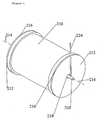
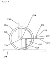
- Figure 1 comprises a sealed cylindrical container (210) which will normally be constructed of a rust resistant material such as plastic, aluminium or other coated metal such as stainless steel (since the container will preferably contain water as a liquid medium).
- the cylinder (210) is provided with two circular cover seals or cover plates (212) mounted coaxially with a primary axis (214) of the cylinder.
- Each of the cover plates (212) are provided with appropriate rims (216) upon which the sealed cylindrical container therefore rests.
- the cover plates (212) may be integrally sealed about the cylindrical container (210) such as by welding or adhesive bonding or may be removably fixed thereto such as by the use of appropriate bolt members to allow a removal of one or more of the cover plates to permit access to the internal workings of the container. Such bolts are not shown in the Figures.
- At least one of the cover plates (212) (as shown in Figure 1 ) is provided with a central circular aperture (218) extending therethrough and permitting communication with the interior of the cylindrical container (210).
- This aperture (218) is again mounted so as be concentric with the cylinder axis (214).
- a substantially cylindrical shaft (220) extends through the circular aperture (218) so as to again extend coaxially about the axis (214) into the interior of the cylinder where it is integrally mounted on a floatation member (222) (as shown in Figure 2 and as will be described in more detail below).
- this shaft (220) is supported by an appropriate sealed bearing again mounted coaxially about axis (214) on the end plate (212) so as to permit relative rotation between the cover plate and the shaft (220) whilst maintaining a fluid seal thereabouts to prevent liquid contained within the container (210) leaking through this aperture (218).
- sealed bearings are well understood in the art and need not be described in any detail herein.
- the shaft (220) further comprises an elongate lever member (224) integrally mounted thereon and extending perpendicular thereto.
- the shaft (220) extends coaxially along at least part of the length of the container (210) and is supported on a second internal bearing mechanism, again mounted coaxial with the container axis (214) so that the shaft (220) is freely rotatable within the container but maintained coaxial on the axis (214).
- the shaft (220) will extend the entire length of the container (210) to be mounted on such an internal bearing mounted on the interior surface of the opposed cover plate (212).
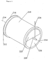
- cover plate (212) has been removed for clarity purposes so as to illustrate the internal configuration of the apparatus of the present invention.
- the shaft (220) has integrally mounted thereon (and restrained from rotation about the shaft (220)) a floatation member (222).
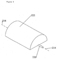
- This floatation member (222), in cross section is substantially hemi-semicircular and is clearly seen in Figure 3 .
- the floatation member (222) is of a comparable length to the internal length of the container (210) so as to extend the majority of the length of such container (210).
- This floatation member (222) is effectively a floating body and may either be constructed of a lightweight low density material such as wood, foam, plastic or other material having a density less than water or, may preferably comprise a hollow container made of plastic or rust resistant metals.
- This floatation member (222) is secured from relative rotation about the shaft (220) by conventional means such as welding thereto or by the use of mechanical restraints such as bolts as will be well understood in the art. The important feature is that the floatation member rotates integrally with the shaft (220).
- the design of the floatation member (222) shown in the present invention is a single elongate member, but this is merely a preferred design and may in fact comprise a plurality of individual float elements or a smaller float element that only extends partway along the length of the container (210). Also, whilst shown here as having a semi-circular profile this is merely to permit ease of rotation of the floatation member (222) about the interior of the container (210) without engaging such container (210). The semi-circular shape permits the maximum size of floatation member (222) although its profile is non-essential to operation of the current invention.
- the container (210) is filled with an appropriate liquid, usually water, although any liquid having a density greater than that of the floatation member (222) can be employed.
- the water is illustrated by use of the reference numeral (226) in Figure 2 and will preferably fill the interior of the container (210).
- the operation function of the apparatus embodied in this cylindrical container (210) will be described with reference to Figures 4 through 9 .
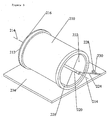
- the embodiment shown in Figures 1 and 2 is in a stable configuration since the reaction force is equal to the upthrust acting on the floatation member (222) and is directed in a vertical plane intersecting the point of contact made between the rims (216) of the cover plates (212) and the horizontal surface (234) and the axis (214), leaving the cylinder (210) balanced.
- the cylinder (210) is not disturbed by the upthrust acting on the floatation member (222).
- the effect of forces due to the mass of the shaft (220), the floatation member (222) and the lever member (224) are assumed negligible and will be disregarded for the purposes of this explanation.
- this pivotal displacement force applied to the lever (224) is, in this embodiment, provided by means of a rotatable wheel (228) mounted coaxially with a cylindrical shaft (230), which shaft (230) having an elongate axis parallel to the axis (214) of the cylinder (210). Since the wheel (228) is freely rotatable about the shaft (230) then its engagement with the lever (224) transfers the pivotal displacement force in a direction perpendicular to the lever (224) as shown substantially in Figure 6 , where the direction of this pivotal displacement force is shown by Arrow (232).
- the pivotal displacement force exerted on the lever (224) is maintained constant by, in this example, a user (not shown) maintaining the displaced lever (224) in a position shown in Figures 5 and 6 thereby applying an appropriate force to the wheel (228).
- the upthrust effected on the floatation member (222) is now represented by the illustrative arrow (236) shown in Figure 6 as acting on the floatation member (222).
- the length of this arrow is indicative of the magnitude of the upthrust and the point of the arrow is shown illustratively placed on the lever at the calculated centre of buoyancy of the floatation member (222) in its displaced position.
- the mass of the displaced fluid or water within the cylinder container (210) is equivalent to this upthrust and represented by the relative length (magnitude) of the arrow (236). This is meant to provide an illustrative view of the inherent upthrust being exerted on the floatation member (222) and hence the lever member (224). It will be appreciated that the magnitude of the pivotal displacement force exerted by the wheel (228) and represented by arrow (232) is considerably less than the magnitude of the upthrust force illustrated by arrow (236). This is due to the distance between the point of application of the force (232) relative to the axis (214) such that the moment exerted by the force (232) is a combination of that force multiplied by the distance from the point of rotation.
- the reaction vector and the resultant vector represent a parallelogram whereby the magnitude of the reaction vector and the magnitude of the resultant vector may be calculated if so required. Furthermore, since the resultant vector is not balanced by any other force and that this force is applied in a direction towards the axis (214), through the lever (224) such force will be exerted through the appropriate bearings to the cylinder (210) and thus will impart a lateral force on the cylinder (210) thereby effecting rotational displacement of that cylinder (210) along the horizontal surface (234).
- pivotal displacement force (232) may be maintained perpendicular to the lever (224) preferably by providing such force with an appropriate mechanism to replicate the displacement of the cylinder (210) and thus maintain the force at a constant distance from the axis (214) whilst maintaining the lever (224) at a constant angle relative to a horizontal plane intersecting the axis (214).
- a mechanical or motorised means for maintaining the appropriate force transmitting member (in this case the wheel (228)) at the desired position relative to the cylinder axis (214) both by means of distance from the cylinder axis (214) and angular configuration relative to the cylinder axis (214), as the cylinder (210) itself is displaced.
- a smaller pivotal displacement force (232) is required if it is applied further away from the axis (as in Figure 6 ) and here the resultant force is of a smaller magnitude and thus the force applied to effect lateral displacement of the drum is less than that that would be incurred by employing the use of a grater pivotal displacement force (232) as shown in Figure 7 .
- the angle or degree of pivotal displacement of the lever (224) can be used to vary the relative rotational speed of the cylindrical container (210) achieved by utilisation of the present invention.
- a smaller rotational displacement force may be employed to move the cylinder (210).
- a specific advantage of this particular embodiment is that the cylinder (210) may be of considerable mass and provided that the lever length (224) is sufficient, then a relatively small pivotal displacement force (232) can be applied to effect rotational displacement of the mass of cylinder (210).
- This provides for a very efficient means of moving a very heavy weight.
- Specific examples could be the movement of very heavy drums of liquid material or drums having weighted materials positioned about their circumference.
- viewing the cylinder (210) shown in Figure 6 specific pockets could be incorporated in to the cylinder or in its inner surface so as to carry materials.
- An operator can then displace the lever (224) by application of relatively small force at a large distance from the axis of the cylinder (214) so as to impart a resultant force (240) acting on the cylinder (210) to allow movement of that cylinder (210) from right to left as viewed in Figure 6 and thus provides a low energy means of moving a very large weight.
- One specific utilisation of the apparatus of this type would be to incorporate such cylinder (210) or cylinders as the main drive wheel/s of a cart or other wheeled vehicle to allow transportation of materials placed upon that vehicle.
- an operator could simply walk behind the cylinder (210) maintaining the appropriate perpendicular pivotal displacement force (232) on the lever (224) to maintain motion of that vehicle, allowing the user to move a weight (that he would not necessarily be able to achieve movement of alone) by utilisation of the resultant buoyancy force (240) exerted on the floatation member (222) within the cylinder (210) and by utilising the mechanical advantage achieved by use of a sufficiently long lever (224).
- the basic inventive concept herein disclosed relies on the translation of the buoyancy upthrust force being exerted on a displaced floatation member (222) to exert a resultant translational force on the axis (214) of that pivotal floatation member (222) and which force is used to effect translational movement of a container (210).
- the resultant translational force applied to the pivot axis of the floatation member can alternatively be used to effect rotational displacement of an article about a second article axis extending perpendicular to such pivot axis.
- the resultant rotational movement of this article can then be used for a number of operations such as a drive mechanism for operating a motor or other mechanical equipment or, through an appropriate gear mechanism to achieve a linear displacement operation of a mechanical apparatus attached thereto.
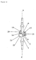
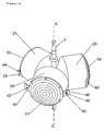
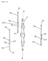
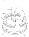
- a substantially vertical drive shaft (1) having an elongate vertical axis (A) about which axis the drive shaft (1) is rotatable.
- This drive shaft (1) is vertically symmetrical about its centre so that its two opposed ends are identical.
- a mounting block (9) Mid-way between its two opposed ends is a mounting block (9) which, in cross section, forms an equilateral triangle, albeit the three apices of such equilateral triangle have been flattened as shown in Figure 10 .
- the three major vertical sides of this triangular block (9) are thus disposed at 120° relative to one another about the axis (A).
- the centre of each of these side walls (2) of the block (9) have holes positioned in the middle thereof and extending perpendicular to such side walls.
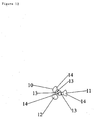
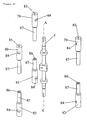
- each of the holes will then receive three identical pins (10,11,12) each of which pins comprises a conical shaped (countersunk) head (14) and have a circumferentially extending groove (13).
- Figure 12 illustrates the spatial relationship of the three pins when inserted in the holes within the block (9).
- Each of the conical shaped heads (14) has a flat outer surface each of which flat outer surface is therefore disposed at 120° to one another so that they extend substantially parallel to the flat faces (2) of the triangular block (9).
- each of the flat apices of the triangular block (9) is provided with an appropriate screw threaded hole (4) allowing an appropriate screw threaded member to be inserted therein so as to engage with the circumferential groove (13) of an associated pin member to hold the pins (10,11,12) within the block (9).
- FIG. 11 three identical bushes (19,15,16) are schematically illustrated, each of which comprise a plurality of screw holes (18). These bushes (19,15,16) are mounted to the main drive shaft (1) by complimentary engagement with the three pin members (10,11,12). The countersunk heads (14) of each pin member will be received in an appropriate corresponding countersunk holes (17) of each bush (19,15,16). In this manner the three bushes (19,15,16) are disposed at 120° to one another and each freely rotatable around their associated pinhead (14). As seen in Figure 10 , three identical bush caps (20, 21, 22) are then connected to each of the bushes (19,15,16) respectively.
- the bush caps (20, 21, 22) are held on the bushes (19,15,16) by screws extending through appropriate holes (23) which correspond with the screw holes (18) on the bushes (19, 15, 16).
- the bush caps (20, 21, 22) serve to maintain the countersunk heads (14) of the pins (10,11,12) in appropriate engagement with the countersunk conical hole (17) of each bush (19,15,16). In this manner, the bushes (19, 15, 16) are now free to rotate about their respective pins (10,11,12).
- each of the bushes (19,15,16) will have a substantially identical floatation member or floatation body (25, 26, 30) connected thereto by use of appropriate screw threaded engagement.
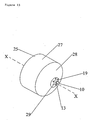
- Each of the floatation members (25, 26, 30) are substantially cylindrical containers having a substantially conical end section (28).
- Each of the conical end sections (28) having substantially flat apices provided with appropriate screw threaded holes (29) to permit screw threaded engagement with the appropriate screw holes (23) on the bush cap (20, 21, 22).
- the screw holes (29) are disposed to as to be eccentric relative to an axis (X) of such cylindrical floatation member (25).
- each of the floatation members (25, 26, 30) are disposed so as to be eccentrically rotatable about the pin axis of each of the three pin members (10,11,12) to which they are mounted.
- the three floatation members (25, 26, 30) are substantially identical and are sealed hollow containers each having, respectively, removable end covers (35, 36, 37) respectively.
- These end covers (35, 36, 37) can be connected onto each floatation member (25, 26, 30) by appropriate screws (not shown) to thereby provide for internal access to the floatation member (25, 26, 30) to allow connection to be effected to the appropriate bushes (19,15,16).
- the covers (35, 36, 37) are then connected to these floatation members (25, 26, 30) to provide sealed buoyant containers.
- each of the covers (35, 36, 37) are provided with two diametrically opposed tabs (40) which extend radially outwards of the floatation members (25, 26, 30) away from floatation member (25, 26, 30) axis (X).
- one of each pair of tabs (40) is provided with a hole (42) to permit attachment of an appropriate weight member so as to counter balance the imbalance achieved by the eccentric location of the pins (10,11,12) with respect to the floatation member (25, 26, 30) axis (X).
- the trailing tabs (40) are provided with appropriate elongate slots (41) for accommodating appropriate force transmitting members in the form of elongate pegs (44, 45, 46) which will be described below.
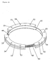
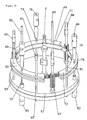
- each of the pegs (44, 45, 46) are disposed on the inner surface of a circular ring gear (49) (which is to be mounted concentrically with the drive shaft axis (A), each peg (44, 45, 46) therefore disposed at an angle of 120° relative to the other one about Axis (A) so that each can be received within the centre of the slot (41) of each associated floatation member (25, 26, 30) respectively, and as shown in Figure 15 .
- the ring gear (49) itself comprises a series of teeth (50) on its outer surface for engagement with an appropriate drive mechanism as will be described below.
- the ring gear (49) is then supported by three substantially identical ring gear guides (51, 52, 53) which permit rotation of the ring gear therein.
- this ring gear (49) is mounted concentrically and coaxially with the main drive shaft (1).
- the three identical ring gear guides (51, 52, 53) each comprise an aperture (54) therethrough for accommodation of guide sticks (73, 74, 75) (as will be described below).
- Each ring gear guide (51, 52, 53) further comprises two additional holes (55) extending therethrough for accommodating support rods (88, 89, 90, 91, 92, 93) for maintaining the ring gear in a pre-determined orientation within the overall apparatus (as will be described below).
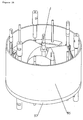
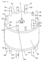
- the apparatus of the second embodiment comprises a sealed container ( Figure 27 ) having a container base (57) which has three screw threaded holes (58) for accommodating base cylinders (81, 82, 83) ( Figure 21 ), together with six holes (59) to accommodate support rods (88, 89, 90, 91, 92, 93) (see Figures 23 ).
- the container base (57) further comprises three housings (60) to accommodate drive gears (65, 66, 67) (as will be described with reference to Figure 18 ) below together with their accompanying flanged bushed bearings (not shown).
- the container base (57) is further provided with a flanged seating (61) for accommodating a cylindrical side wall (95) and a central aperture (62) into which the main drive shaft (1) is inserted as shown.
- the array of holes (58,59, 60) are substantially arranged around the periphery of the circular container base (57).
- the apparatus also comprises a substantially circular container top (63) which is substantially identical to the container base (57) with the exception that the housings (60) are replaced with holes (64) passing completely through the container top (63) whereas the housing (60) only extends partway through the depth of the container base (57).
- the container top (63) further comprises three screw threaded holes (58) for accommodating top cylinders (78, 79, 80) (see Figure 21 ), together with six holes (59) for support rods (88, 89, 90, 91, 92, 93) (see Figures 23 ), together with three holes (64) for accommodating the drive gears (65, 66, 67) (see Figure 18 ) and their accompanying bush bearings and accompanying seals (not shown).
- the container top (63) is provided with an appropriate flange seating (61) together with appropriate hole (62) for accommodating the main shaft (1) as shown.
- Appropriate flanged bush bearings and accompanying seals are positioned between the drive shaft (1) and both the container base (57) and container top (63) to permit rotation of the shaft (1) between these container base (57) and container top (63) and also to provide an appropriate fluid seal therebetween.
- the main shaft (1) extends beyond the container base (57) and the container top (63) thereby enabling an appropriate coupling (not shown) to be made with the main shaft (1) via the three key ways (8) in the form of three longitudinally slots disposed at 120° relative to one another about the axis (A).
- each of these drive gears further comprises a cylindrical surface (69) for accommodation within the three respective holes (64) of the container top (63) whereby appropriate flange shaft seals (not shown) permit a rotatable seal between the container top (63) and these drive gears (65, 66, 67).
- Each of the drive gears (65, 66, 67)further comprises a second cylindrical surface (70) to be accommodated within an inner portion of each hole (64) together with accompanying bush bearings (not shown).
- each drive gear (65, 66, 67) is provided with a flange seating (71) to be accommodated within the housing (60) of the container base (57), together with appropriate accompanying flange bush bearings (not shown).
- a flange seating (71) to be accommodated within the housing (60) of the container base (57), together with appropriate accompanying flange bush bearings (not shown).
- Each of the drive gears (65, 66, 67) is fitted between the container base (57) and the container top (63) with appropriate bushing permitting such drive gears (65, 66, 67) to be rotatable about their respective longitudinal axis (which axis extend parallel with the drive shaft axis (A).
- rotation of the drive gears (65, 66, 67) effects rotation of the ring gear (49) as for a conventional gear mechanism.
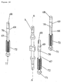
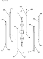
- FIG 19 there are shown three identical guide sticks (73, 74, 75) in the form of elongate cylindrical rods each having a cylindrical saddle (177) partway along the length whereby each saddle (177) is provided with an appropriate circumferential groove (76) for accommodating circlips (not shown).
- Each of these guide sticks (73, 74, 75) is further provided with a piston (77) at each end thereof and which pistons are intended for accommodating appropriate cover seals (not shown).
- the guide sticks (73, 74, 75) are positioned within the holes (54) of their respective ring gear guide (51, 52, 53) by means of appropriate circlips engaging with the circumferential grooves (76).
- the apparatus is further provided with three identical top cylindrical end stops (78, 79, 80) and three identical base cylindrical end stops (81, 82, 83) ( Figure 21 ).
- Each of the end stops (78, 79, 80, 81, 82, 83) comprise appropriate flats (84) for accommodating use of a spanner or other tool to allow forced rotation thereof.
- each of the end stops (78, 79, 80, 81, 82, 83) is further provided on an outer circular face thereof with an appropriate screw threaded aperture (85) for receiving a screw threaded member to allow appropriate hydraulic fluid to be pumped in or out of these end stops (78, 79, 80, 81, 82, 83).
- each of the end stops (78, 79, 80, 81, 82, 83) is provided with an inner bore (86) for accommodating a piston (77) of each of the guide sticks (73, 74, 75) respectively.
- each of the six end stops (78, 79, 80, 81, 82, 83) shown in Figure 21 will be positioned so as to be accommodated on the opposed ends of each guide stick (73, 74, 75) of Figure 19 , (as shown in Figure 22 ).
- the top cylindrical end stops (78, 79, 80) are substantially identical to the base cylindrical end stops (81, 82, 83) with the exception that external screw threaded portions (87) of the top cylindrical end stops (78, 79, 80) is longer than external screw threaded portions (87) of the base cylindrical end stops (81, 82, 83) as shown.
- Figure 22 shows the base cylindrical end stops (81, 82, 83) each screwed into their respective holes (58) in the container base (57), and each of which receives a piston (77) of an associated guide stick (73, 74, 75) within the aperture (86) thereof.
- each guide stick (73, 74, 75) and appropriate accompanying cover seals (not shown) are then received within the bores (86) of their respective top cylindrical end stops (78, 79, 80).
- the guide sticks (73, 74, 75) are maintained within the appropriate holes (54) of their respective ring gear guides (51, 52, 53) by means of circlips engaging within grooves (76) so as to retain the ring gear guides (51, 52, 53) fixed along the length of each guide stick (73, 74, 75).
- each of the cylindrical end stops (78, 79, 80, 81, 82, 83) has an appropriate aperture (85) to allow hydraulic fluid to be pumped in or out of these cylindrical end stops (78, 79, 80, 81, 82, 83) so as to hydraulically displace the pistons (77) of the guide stick (73, 74, 75) which effectively causes relative movement of the saddles (177) of the guide sticks (73, 74, 75). Since the saddles (177) are retained by the respective ring gear guides (51, 52, 53), movement of such saddles (177) also causes displacement of the ring gear guides (51, 52, 53) in a vertical direction towards or away from the container base (57) as desired. This provides a means of hydraulically adjusting the height of the ring gear guides (51, 52, 53) and the associated ring gear (49) about the height of the apparatus and relative to the longitudinal length of the main drive shaft (1).
- FIG 23 now shows six identical support rods (88, 89, 90, 91, 92, 93), each having about their longitudinally opposed ends external screw threads (94) for receipt of appropriate screw threaded rod ends (96, 97, 98, 99,100,101,102,103, 104, 106, 107, 108) as seen in Figure 28 .
- Each of the external screw threaded ends (94) of these identical rods extend through the respective holes (59) in both the container top (63) and container base (57).
- FIG 25 similar to Figure 24 , now simply shows the three flotation members (25, 26, 30) mounted (as previously described) on the main drive shaft (1) and disposed within the apparatus such that the pegs (44, 45, 46) mounted on the inner surface of the ring gear (49) are now received within the appropriate elongate slots (41) of each floatation member as shown in Figure 14 and 16 .
- the floatation members (25, 26, 30) are caused to rotate eccentrically about the respective mounting pins (10,11,12) on the drive shaft (1).
- the apparatus of the second embodiment is then provided with a cylindrical outer wall (95) ( Figure 26 ) which is received in a substantially fluid sealed fit on the flange seatings (61) of the container base (57) and the container top (63) (reference Figure 17 ).
- the container top (63) is mounted on this wall (95) whereby appropriate screw threaded rod ends (96, 97, 98, 99,100, 101, 102, 103, 104, 106, 107, 108) (which are effectively sealed screw threaded nuts) are then engaged in a screw threaded relationship with the external screw threaded ends (94) of each of the rods (88, 89, 90, 91, 92, 93) respectively and, through use of appropriate flats (105) formed on each of these rod ends (96, 97, 98, 99, 100, 101 , 102, 103, 104, 106, 107, 108) screw threaded engagement therebetween effectively seals the apparatus as shown in Figure 28 .
- appropriate screw threaded rod ends (96
- the apparatus Prior to fitment of the container top (63), the apparatus is filled with an appropriate fluid such as water or oil in which the floatation members (25, 26, 30) are caused to float since they have a lower density than that of the liquid used.
- an appropriate fluid such as water or oil
- these floatation members (25, 26, 30) will seek an equilibrium position when the apparatus is maintained in a substantially horizontal configuration such that the tab (40) is therefore disposed higher than the other tab (40) due to the eccentric rotation of these floatation devices.
- the ring gear guide (51,52,53) can be lowered within the apparatus of Figure 28 hence effecting a lowering of the associated ring gear (49). Since the pegs (44, 45, 46) are integrally mounted on the inner surface of this ring gear (49) they are also lowered with respect to the apparatus and in a direction parallel to the axis of the drive shaft (1).
- this downward movement of the ring gear (49) further serves to displace the respective tabs (40) of each floatation member (25, 26, 30) in a downward direction so as to effect eccentric rotation of the floatation members (25, 26, 30) out of their normal equilibrium position and thus incurring a resultant buoyancy upthrust being exerted thereon as the displaced fluid (caused by this movement) exerts an upthrust force attempting to return the displaced floatation members (25, 26, 30) to their equilibrium position.
- the basic principle of operation of the apparatus of the second embodiment is similar to that as described with reference to Figures 1 through 10 .
- the floatation member (25) is eccentrically mounted about an eccentric pivot axis (300) which is radially remote from the central axis (x-x) of such cylinder which provides a centre of buoyancy of such cylinder.
- the two tabs (41) are horizontally aligned on a horizontal plane (400)
- a moment is created on the cylinder (25) due to the resultant buoyancy or upthrust exerted on this container by the liquid within the apparatus substantially indicated by arrow (336).
- This upthrust seeks to return the cylinder to an equilibrium position whereby the axis (x-x) of the cylinder would lie vertically above the pivot axis (300).
- the peg (44) engages with the elongate slot (41) of the tab (40) to provide a counter balancing force maintaining the cylinder in this displaced configuration.
- a resultant rotational force is applied by the peg (44) to the cylinder so as to counter balance the resultant upthrust (336) and thus maintain equilibrium.
- This rotational force applied to the pegs (44) is achieved by appropriate manipulation of the ring gear as previously mentioned.
- the resultant resolution of this pivotal displacement force (330) and the upthrust (336), is a resultant force vector (340) which is transmitted through the pivot axis (300) of this floatation member (25) (and thus one of the pin (10)) to effect a rotational force transmitted to the main drive shaft (1) which will effect rotation of that main drive shaft (1) about its axis (A).
- each of the three floatation members (25, 26, 30) will be effected simultaneously in a similar manner so that the rotational drive force exerted on the drive shaft (1) will be magnified threefold.
- the pivotal displacement force (330) must be maintained perpendicular to the elongate slot (41) (which slot performing a similar function as the lever member (224) of the first embodiment) and for this reason, the pegs (44, 45, 46) are mounted on a drive gear (49) which itself is rotatable within the apparatus through engagement with the rotatable drive gears (65,66,67).
- drive gears are connected to an appropriate external drive mechanism (not shown, but could include a simple motor or other manually displaceable mechanism to effect rotation of the drive gears (65 , 66, 67)) whereby the rotation of such drive gears (65, 66, 67) causes meshed engagement between the teeth of such drive gears (65, 66, 67) and the teeth (50) of the ring gear (49) so as to effect rotation of this ring gear (49) coaxially about the drive shaft (1).
- an appropriate external drive mechanism not shown, but could include a simple motor or other manually displaceable mechanism to effect rotation of the drive gears (65 , 66, 67)
- meshed engagement between the teeth of such drive gears (65, 66, 67) and the teeth (50) of the ring gear (49) so as to effect rotation of this ring gear (49) coaxially about the drive shaft (1).
- the speed of rotation of the ring gear (49) be consistent with the speed of rotation of the drive shaft (1) caused by the resolved upthrust.
- the pegs (44, 45, 46) are maintained substantially within the centre of the elongate slots (41) so as not to abut or engage the end surfaces of such slots (41). Should the pegs (44, 45, 46) abut the end surfaces of such slots (41), then additional translational forces will be applied to the floatation members (25, 26, 30) providing at least one force vector countering the resultant force (340) achieved by the upthrust.
- drive control of the apparatus can be varied by adjusting the relative angle of between the elongate slot (41) and a horizontal plane (400) as shown in Figure 29 , such that again the greater this angle then the greater the size of the resultant vector which increases the speed of rotation of the drive shaft (1). If the speed of rotation of the drive shaft (1) increases then adjustment of the speed of rotation of the ring gear (49) is also required to maintain the peg (44) in the centre of the elongate slot (41) so as to maintain the pivotal displacement force perpendicular thereto. In addition, it will also be appreciated that the further the slot (41) is from the pivot axis (300) of the floatation members (25) then the greater the mechanical advantage can be achieved.
- pivotal displacement force Whilst the pivotal displacement force is achieved hydraulically, it is still advantageous to minimise the required pivotal displacement force so as to minimise frictional resistance between the ring gear (49) and the ring gear guides (51, 52, 53). Hence, the smaller the pivotal displacement force the smaller the frictional resistance and thus the efficiency of the apparatus is further increased.
- the second embodiment thus utilises the buoyancy upthrust force exerted on a floatation member (25, 26, 30) disposed past an equilibrium position to create a resultant drive force through the pivot axis of the floatation member (25, 26, 30) which, in this embodiment, is used to effect rotational displacement of a drive shaft (1) about a substantially vertical axis (A).
- Rotation of this drive shaft (1), and specifically its external key way (8), can then be used as a rotary output for driving other apparatus such as a gear mechanism, wheels or other mechanical devices.
- it can be connected to an appropriate gear mechanism for converting rotary to linear motion to effect a linear drive member.
- this apparatus provides a means of utilising a buoyancy upthrust force on a floatation member (25, 26, 30) to assist in effecting non-vertical displacement of an article such as a drive shaft (1) (or a rotary drum according to the first embodiment). Since energy input is required to maintain the pivotal displacement force perpendicular to either the lever member (224) or the elongate slot (41) of the second embodiment it will be appreciated that the output or resultant force is not dependent solely on the buoyancy force but also requires a certain energy input to maintain the pivotal displacement force perpendicular to the appropriate displacement lever, but the upthrust created is used to significantly enhance the energy output of the apparatus.
- the two embodiments described herein utilise contained fluid medium within either the cylinder (210) of the embodiment shown in Figure 1 or within the cylindrical outer wall (95) of the apparatus of the second embodiment as shown in Figure 27 .
- the provision of such a contained fluid medium is for ease of manoeuvrability and operation of the current invention remote from a permanent water source.
- the invention is equally applicable in a scenario whereby the fluid medium is not contained within the apparatus but the apparatus it itself completely or partially immersed in the fluid medium.
- both the devices shown in the described embodiment will work equally as well if placed within a non-contained water source such as a pool, river or ocean.
- the end plates (212) could simply be omitted and the apparatus completely or partially submerged within an appropriate liquid such as a river. Whereby such liquid will again cause the floatation member to seek an equilibrium position in a manner similar to that described for the embodiment shown in Figure 1 whereby the fluid medium is wholly contained within the cylindrical drum.
- the cylindrical outer wall (95) can simply be omitted and the device again completely or partially submerged in an appropriate liquid such as water or oil.
Landscapes
- Engineering & Computer Science (AREA)
- Chemical & Material Sciences (AREA)
- Combustion & Propulsion (AREA)
- Mechanical Engineering (AREA)
- General Engineering & Computer Science (AREA)
- Centrifugal Separators (AREA)
- Transmission Devices (AREA)
- Other Liquid Machine Or Engine Such As Wave Power Use (AREA)
- Valve-Gear Or Valve Arrangements (AREA)
- Finish Polishing, Edge Sharpening, And Grinding By Specific Grinding Devices (AREA)
- Valve Device For Special Equipments (AREA)
- Permanent Magnet Type Synchronous Machine (AREA)
- Motor Or Generator Frames (AREA)
Claims (21)
- Vorrichtung zum Verwenden der Auftriebskraft auf ein Schwimmelemenit (222), um die Verschiebung eines drehbaren Gegenstands (210) in einer nicht vertikalen Richtung zu unterstützen, während die Vorrichtung umfasst: mindestens ein schwenkbar befestigtes Schwimmelement (222), das mindestens teilweise in einem flüssigen Medium eingetaucht ist, und ein verschiebbares Betätigungselement (224), das fest mit dem Schwimmelement verbunden ist, während das Schwimmelement (222) fest an dem bewegbaren Gegenstand um eine sich davon erstreckende Schwenkachse (214) befestigt ist, wobei das Schwimmelement (222) schwenkbar um die Schwenkachse (214) in dem flüssigen Medium und hinter eine Ausgleichsposition durch Anwendung einer schwenkenden Verschiebekraft verschiebbar ist, die auf das Betätigungselement (224) angewandt wird, um eine Auftriebskraft an dem Schwimmelement (222) zu erzeugen, während Mittel bereitgestellt sind, um die schwenkende Verschiebekraft in einer Richtung senkrecht zu dem Betätigungselement (224) anzuwenden und aufrechtzuerhalten, wodurch ein resultierender Kraftvektor von der Auftriebskraft auf das Schwimmelement (222) erzeugt wird, der sich senkrecht zu der Schwenkachse (214) erstreckt und auf den Gegenstand übertragbar ist, um eine Verschiebung des Gegenstands zu bewirken, dadurch gekennzeichnet, dass die Vorrichtung weiterhin umfasst: ein verschiebbares Kraftübertragungselement (228) zum Bewirken der Verschiebung der schwenkenden Verschiebekraft, um so die schwenkende Verschiebekraft konstant in Bezug auf und rechtwinklig mit dem verschiebbaren Betätigungselement (224) während des Verschiebens des Gegenstands zu halten, während das Kraftübertragungselement angetrieben wird.
- Vorrichtung gemäß Anspruch 1, weiterhin umfassend einen abgedichteten Körper zum Enthalten des flüssigen Mediums in dem das Schwimmelement mindestens teilweise eingetaucht ist.
- Vorrichtung gemäß einem der vorhergehenden Ansprüche, in der das Betätigungselement radial von der Schwenkachse entfernt ist, um so einen mechanischen Vorteil durch die Anwendung der schwenkenden Verschiebekraft darauf zu erzielen.
- Vorrichtung gemäß einem der vorhergehenden Ansprüche, in der das Betätigungselement einen Hebemechanismus umfasst.
- Vorrichtung gemäß Anspruch 4 in Abhängigkeit von Anspruch 1, während der Hebemechanismus koaxial zum Schwimmelement um die Schwenkachse befestigt ist.
- Vorrichtung gemäß Anspruch 1, in der das Kraftübertragungselement motorbetrieben ist.
- Vorrichtung gemäß einem der vorhergehenden Ansprüche, in der der Gegenstand drehbar ist.
- Vorrichtung gemäß Anspruch 7, in der der Gegenstand drehbar um eine Achse ist, die koaxial mit der Schwenkachse ist.
- Vorrichtung gemäß Anspruch 8, in der der Gegenstand lateral in Bezug auf eine Richtung der Auftriebskraft verschiebbar ist.
- Vorrichtung gemäß Anspruch 8 oder Anspruch 9, in der der Gegenstand eine zylindrische Trommel aufweist, die das flüssige Medium und die Schwimmvorrichtung umfasst und dessen Trommel sich koaxial zu der Schwenkachse erstreckt.
- Vorrichtung gemäß Anspruch 7, in der der Gegenstand drehbar um eine Gegenstandsachse senkrecht zu der Schwenkachse ist.
- Vorrichtung gemäß Anspruch 11 mit einem externen Antriebsmechanismus, der mit dem drehbaren Gegenstand verbunden ist und durch diesen betrieben wird.
- Vorrichtung gemäß entweder Anspruch 11 oder Anspruch 12, in Abhängigkeit von Anspruch 6, in der das verschiebbare Kraftübertragungselement sich koaxial zur Gegenstandsachse erstreckt.
- Vorrichtung gemäß einem der Ansprüche 11 bis 13, umfassend eine Mehrzahl an Schwimmelamenten, die radial um die Gegenstandsachse angeordnet und schwenkend mit dieser verbunden ist.
- Vorrichtung gemäß Anspruch 14, in der das Kraftübertragungselement umfasst: eine kreisförmige Vorrichtung, die koaxial zur Gegenstandsachse befestigt ist, um die schwenkende Verschiebekraft, die auf jedes aus der Mehrzahl der Schwimmelement angewandt wird, in Bezug auf und senkrecht zu jedem verschiebbaren dazugehörigen Betätigungselement konstant aufrechtzuerhalten.
- Ein Verfahren des Verwendens der Auftriebskraft auf ein Schwimmelement (222), um die Verschiebung eines bewegbaren Gegenstands (210) in einer nicht vertikalen Richtung zu unterstützen, wobei das Verfahren die Schritte aufweist:Verbinden eines schwenkend verschiebbaren Schwimmelements (222) mit dem Gegenstand um eine Schwenkachse (214) des Schwirnmelements,Anbringen einer Schwenkverschiebekraft auf ein Betätigungselement (224) des Schwimmelements (222) in einer Richtung senkrecht zu dem Betätigungselement (224), um eine schwenkende Verschiebung des Schwimmelements (222) in einem flüssigen Medium hinter eine Gleichgewichtsposition zu bewirken,Aufrechterhalten der Verschiebekraft senkrecht zu dem Betätigungselement (224), um einen resultierenden Kraftvektor der Auftriebskraft auf das Schwimmelement zu erzeugen, der senkrecht durch die Schwenkachse (214) auf den Gegenstand übertragen wird, um eine Verschiebung des Gegenstands zu bewirken,dadurch gekennzeichnet, dass das Verfahren weiterhin die Schritte aufweist:Verwenden eines Kraftübertragungselements (228), um das Verschieben der schwenkenden Verschiebekraft zu bewirken, um so die schwenkende Verschiebekraft konstant in Bezug auf und senkrecht zu dem Betätigungselement (224) während des Verschiebens des Gegenstands zu halten, und Antreiben des Kraftübertragungselements.
- Ein Verfahren gemäß Anspruch 16, weiterhin umfassend: Bereitstellen des Betätigungselements mit einer vorbestimmten Länge, während die Anwendung der schwenkenden Verschiebekraft entfernt von der Schwenkachse in einem vorbestimmten Abstand von der Schwenkachse bewirkt wird, um einen vorbestimmten mechanischen Vorteil bereitzustellen, der eine kleinere Kraft als die resultierende Auftriebskraft ermöglicht, um das Verschieben des Schwimmelements hinter seine Gleichgewichtsposition zu bewirken.
- Ein Verfahren gemäß Anspruch 16 oder Anspruch 17, umfassend: Einstellen des resultierenden Kraftvektors, der auf den Gegenstand übertragen wird, durch Einstellen des Winkels zwischen dem Punkt der Anwendung der schwenkenden Verschiebekraft auf das Betätigungselement im Bezug auf eine horizontale Ebene, die die Schwenkachse schneidet.
- Ein Verfahren gemäß Anspruch 18, umfassend: Erhöhen des resultierenden Kraftvektors durch Erhöhen des Winkels.
- Ein Radfahrzeug mit mindestens einem Rad, umfassend eine Vorrichtung gemäß einem der Ansprüche 1 bis 10.
- Ein Motor, umfassend eine Vorrichtung gemäß einem der Ansprüche 11 bis 15.
Applications Claiming Priority (7)
| Application Number | Priority Date | Filing Date | Title |
|---|---|---|---|
| GB0224464 | 2002-10-21 | ||
| GB0224464A GB0224464D0 (en) | 2002-10-21 | 2002-10-21 | Force generating device |
| GB0225684 | 2002-11-04 | ||
| GB0225684A GB0225684D0 (en) | 2002-11-04 | 2002-11-04 | Force generating device |
| GB0312948 | 2003-06-05 | ||
| GB0312948A GB0312948D0 (en) | 2003-06-05 | 2003-06-05 | Force transmitting apparatus |
| PCT/GB2003/004512 WO2004036037A1 (en) | 2002-10-21 | 2003-10-20 | Buoyancy motor |
Publications (2)
| Publication Number | Publication Date |
|---|---|
| EP1554492A1 EP1554492A1 (de) | 2005-07-20 |
| EP1554492B1 true EP1554492B1 (de) | 2009-12-23 |
Family
ID=32110562
Family Applications (1)
| Application Number | Title | Priority Date | Filing Date |
|---|---|---|---|
| EP03753818A Expired - Lifetime EP1554492B1 (de) | 2002-10-21 | 2003-10-20 | Auftriebsmotor |
Country Status (7)
| Country | Link |
|---|---|
| US (1) | US7056176B2 (de) |
| EP (1) | EP1554492B1 (de) |
| JP (1) | JP4503529B2 (de) |
| AT (1) | ATE453051T1 (de) |
| AU (1) | AU2003271979A1 (de) |
| DE (1) | DE60330697D1 (de) |
| WO (1) | WO2004036037A1 (de) |
Families Citing this family (3)
| Publication number | Priority date | Publication date | Assignee | Title |
|---|---|---|---|---|
| US20100127500A1 (en) * | 2008-11-25 | 2010-05-27 | Yingchen Yang | Method and apparatus for energy harvesting from ocean waves |
| US20150040556A1 (en) * | 2013-08-12 | 2015-02-12 | Arvind A. Daya | Zero emissions power plant |
| GB202216180D0 (en) * | 2022-11-01 | 2022-12-14 | Isaac Felix | Force deflection arrangement |
Family Cites Families (7)
| Publication number | Priority date | Publication date | Assignee | Title |
|---|---|---|---|---|
| US2097286A (en) * | 1936-11-02 | 1937-10-26 | Lloyd S Mcgee | Power generating apparatus |
| US2730631A (en) * | 1953-03-30 | 1956-01-10 | Juliana S Dandini | Current-driven motor |
| US4499725A (en) * | 1983-06-29 | 1985-02-19 | Marino Sbrizzai | Hydraulic machine |
| US4737070A (en) * | 1985-07-31 | 1988-04-12 | Yamaha Hatsudoki Kabushiki Kaisha | Water powered device |
| GB8829822D0 (en) | 1988-12-21 | 1989-02-15 | Issac Felix | A device to enable an applied displacement to produce rotation |
| FR2717862A1 (fr) * | 1993-08-27 | 1995-09-29 | Des Moutis Robert | Convertisseur de différences de pression. |
| US6616403B1 (en) * | 2002-04-08 | 2003-09-09 | Matt H. Smith | Floating electric generator |
-
2003
- 2003-10-20 JP JP2005501318A patent/JP4503529B2/ja not_active Expired - Fee Related
- 2003-10-20 AU AU2003271979A patent/AU2003271979A1/en not_active Abandoned
- 2003-10-20 AT AT03753818T patent/ATE453051T1/de not_active IP Right Cessation
- 2003-10-20 EP EP03753818A patent/EP1554492B1/de not_active Expired - Lifetime
- 2003-10-20 DE DE60330697T patent/DE60330697D1/de not_active Expired - Lifetime
- 2003-10-20 WO PCT/GB2003/004512 patent/WO2004036037A1/en not_active Ceased
-
2005
- 2005-04-21 US US11/111,407 patent/US7056176B2/en not_active Expired - Fee Related
Also Published As
| Publication number | Publication date |
|---|---|
| JP2006516314A (ja) | 2006-06-29 |
| US7056176B2 (en) | 2006-06-06 |
| DE60330697D1 (de) | 2010-02-04 |
| AU2003271979A1 (en) | 2004-05-04 |
| ATE453051T1 (de) | 2010-01-15 |
| JP4503529B2 (ja) | 2010-07-14 |
| WO2004036037A1 (en) | 2004-04-29 |
| EP1554492A1 (de) | 2005-07-20 |
| US20050186864A1 (en) | 2005-08-25 |
Similar Documents
| Publication | Publication Date | Title |
|---|---|---|
| US7950563B2 (en) | Apparatus and method for bearing a tool against a workpiece | |
| AU602552B2 (en) | Improvements in or relating to torque wrenches | |
| US20040240996A1 (en) | Lift motor | |
| SE437809B (sv) | Vagmotor for framdrivning av en flytande anordning | |
| CA3016805A1 (en) | Device for conversion of wave energy into electrical energy and the process for its deployment at the exploitation location | |
| US8925312B2 (en) | Propulsion or motor device for converting energy into power, using the forces generated by the surface movement of a liquid or fluid or the like | |
| US7056176B2 (en) | Buoyancy motor | |
| MX2010011300A (es) | Dispositivo de multiplicacion, preferiblemente dispositivo motor. | |
| CN111058771A (zh) | 一种潜器搭载的海底多点位冲击钻进取岩芯微型钻机 | |
| EP3081806A1 (de) | Vorrichtung zur umwandlung von wellenenergie in elektroenergie | |
| FR2388284A1 (fr) | Dispositif pour propulser un projectile liquide dans un milieu liquide a fin de creation d'une onde de choc | |
| CN211651235U (zh) | 一种全电动金属液倒包装置 | |
| CN210715800U (zh) | 一种用于工业设备的新型滚珠丝杆 | |
| CN224242528U (zh) | 一种装配式建筑构件精准定位吊装夹具 | |
| US20070271916A1 (en) | Device for Producing Energy | |
| CN116923959B (zh) | 一种用于更换水下传感器的机器人 | |
| US11530575B2 (en) | Vibration generator for an drilling installation, underwater drilling installation and underwater drilling system | |
| CN111305217A (zh) | 一种用于抛石整平船的翻转装置及抛石整平船 | |
| CN223836556U (zh) | 一种码垛机的抓取装置 | |
| CN220135213U (zh) | 一种氯气储罐加固结构 | |
| CN222539381U (zh) | 一种方便装载的运输转运装置 | |
| CN118953594B (zh) | 一种船用层压木支座及支撑方法 | |
| CN221582627U (zh) | 一种油罐筒体生产用铆焊装置 | |
| CN224174050U (zh) | 一种方便钻探的井壁取芯器 | |
| US20060037314A1 (en) | Energy multiplier |
Legal Events
| Date | Code | Title | Description |
|---|---|---|---|
| PUAI | Public reference made under article 153(3) epc to a published international application that has entered the european phase |
Free format text: ORIGINAL CODE: 0009012 |
|
| 17P | Request for examination filed |
Effective date: 20050420 |
|
| AK | Designated contracting states |
Kind code of ref document: A1 Designated state(s): AT BE BG CH CY CZ DE DK EE ES FI FR GB GR HU IE IT LI LU MC NL PT RO SE SI SK TR |
|
| AX | Request for extension of the european patent |
Extension state: AL LT LV MK |
|
| DAX | Request for extension of the european patent (deleted) | ||
| 17Q | First examination report despatched |
Effective date: 20081105 |
|
| GRAP | Despatch of communication of intention to grant a patent |
Free format text: ORIGINAL CODE: EPIDOSNIGR1 |
|
| GRAS | Grant fee paid |
Free format text: ORIGINAL CODE: EPIDOSNIGR3 |
|
| GRAA | (expected) grant |
Free format text: ORIGINAL CODE: 0009210 |
|
| AK | Designated contracting states |
Kind code of ref document: B1 Designated state(s): AT BE BG CH CY CZ DE DK EE ES FI FR GB GR HU IE IT LI LU MC NL PT RO SE SI SK TR |
|
| REG | Reference to a national code |
Ref country code: GB Ref legal event code: FG4D |
|
| REG | Reference to a national code |
Ref country code: CH Ref legal event code: EP |
|
| REG | Reference to a national code |
Ref country code: IE Ref legal event code: FG4D |
|
| REF | Corresponds to: |
Ref document number: 60330697 Country of ref document: DE Date of ref document: 20100204 Kind code of ref document: P |
|
| REG | Reference to a national code |
Ref country code: NL Ref legal event code: VDEP Effective date: 20091223 |
|
| PG25 | Lapsed in a contracting state [announced via postgrant information from national office to epo] |
Ref country code: SE Free format text: LAPSE BECAUSE OF FAILURE TO SUBMIT A TRANSLATION OF THE DESCRIPTION OR TO PAY THE FEE WITHIN THE PRESCRIBED TIME-LIMIT Effective date: 20091223 Ref country code: FI Free format text: LAPSE BECAUSE OF FAILURE TO SUBMIT A TRANSLATION OF THE DESCRIPTION OR TO PAY THE FEE WITHIN THE PRESCRIBED TIME-LIMIT Effective date: 20091223 |
|
| PG25 | Lapsed in a contracting state [announced via postgrant information from national office to epo] |
Ref country code: SI Free format text: LAPSE BECAUSE OF FAILURE TO SUBMIT A TRANSLATION OF THE DESCRIPTION OR TO PAY THE FEE WITHIN THE PRESCRIBED TIME-LIMIT Effective date: 20091223 |
|
| PG25 | Lapsed in a contracting state [announced via postgrant information from national office to epo] |
Ref country code: AT Free format text: LAPSE BECAUSE OF FAILURE TO SUBMIT A TRANSLATION OF THE DESCRIPTION OR TO PAY THE FEE WITHIN THE PRESCRIBED TIME-LIMIT Effective date: 20091223 |
|
| PG25 | Lapsed in a contracting state [announced via postgrant information from national office to epo] |
Ref country code: BG Free format text: LAPSE BECAUSE OF FAILURE TO SUBMIT A TRANSLATION OF THE DESCRIPTION OR TO PAY THE FEE WITHIN THE PRESCRIBED TIME-LIMIT Effective date: 20100323 Ref country code: RO Free format text: LAPSE BECAUSE OF FAILURE TO SUBMIT A TRANSLATION OF THE DESCRIPTION OR TO PAY THE FEE WITHIN THE PRESCRIBED TIME-LIMIT Effective date: 20091223 Ref country code: PT Free format text: LAPSE BECAUSE OF FAILURE TO SUBMIT A TRANSLATION OF THE DESCRIPTION OR TO PAY THE FEE WITHIN THE PRESCRIBED TIME-LIMIT Effective date: 20100423 Ref country code: NL Free format text: LAPSE BECAUSE OF FAILURE TO SUBMIT A TRANSLATION OF THE DESCRIPTION OR TO PAY THE FEE WITHIN THE PRESCRIBED TIME-LIMIT Effective date: 20091223 Ref country code: EE Free format text: LAPSE BECAUSE OF FAILURE TO SUBMIT A TRANSLATION OF THE DESCRIPTION OR TO PAY THE FEE WITHIN THE PRESCRIBED TIME-LIMIT Effective date: 20091223 Ref country code: ES Free format text: LAPSE BECAUSE OF FAILURE TO SUBMIT A TRANSLATION OF THE DESCRIPTION OR TO PAY THE FEE WITHIN THE PRESCRIBED TIME-LIMIT Effective date: 20100403 |
|
| PG25 | Lapsed in a contracting state [announced via postgrant information from national office to epo] |
Ref country code: CZ Free format text: LAPSE BECAUSE OF FAILURE TO SUBMIT A TRANSLATION OF THE DESCRIPTION OR TO PAY THE FEE WITHIN THE PRESCRIBED TIME-LIMIT Effective date: 20091223 Ref country code: BE Free format text: LAPSE BECAUSE OF FAILURE TO SUBMIT A TRANSLATION OF THE DESCRIPTION OR TO PAY THE FEE WITHIN THE PRESCRIBED TIME-LIMIT Effective date: 20091223 Ref country code: SK Free format text: LAPSE BECAUSE OF FAILURE TO SUBMIT A TRANSLATION OF THE DESCRIPTION OR TO PAY THE FEE WITHIN THE PRESCRIBED TIME-LIMIT Effective date: 20091223 |
|
| PG25 | Lapsed in a contracting state [announced via postgrant information from national office to epo] |
Ref country code: GR Free format text: LAPSE BECAUSE OF FAILURE TO SUBMIT A TRANSLATION OF THE DESCRIPTION OR TO PAY THE FEE WITHIN THE PRESCRIBED TIME-LIMIT Effective date: 20100324 Ref country code: CY Free format text: LAPSE BECAUSE OF FAILURE TO SUBMIT A TRANSLATION OF THE DESCRIPTION OR TO PAY THE FEE WITHIN THE PRESCRIBED TIME-LIMIT Effective date: 20091223 |
|
| PLBE | No opposition filed within time limit |
Free format text: ORIGINAL CODE: 0009261 |
|
| STAA | Information on the status of an ep patent application or granted ep patent |
Free format text: STATUS: NO OPPOSITION FILED WITHIN TIME LIMIT |
|
| 26N | No opposition filed |
Effective date: 20100924 |
|
| PG25 | Lapsed in a contracting state [announced via postgrant information from national office to epo] |
Ref country code: DK Free format text: LAPSE BECAUSE OF FAILURE TO SUBMIT A TRANSLATION OF THE DESCRIPTION OR TO PAY THE FEE WITHIN THE PRESCRIBED TIME-LIMIT Effective date: 20091223 |
|
| PGFP | Annual fee paid to national office [announced via postgrant information from national office to epo] |
Ref country code: FR Payment date: 20101117 Year of fee payment: 8 |
|
| PGFP | Annual fee paid to national office [announced via postgrant information from national office to epo] |
Ref country code: DE Payment date: 20101125 Year of fee payment: 8 |
|
| PG25 | Lapsed in a contracting state [announced via postgrant information from national office to epo] |
Ref country code: IT Free format text: LAPSE BECAUSE OF FAILURE TO SUBMIT A TRANSLATION OF THE DESCRIPTION OR TO PAY THE FEE WITHIN THE PRESCRIBED TIME-LIMIT Effective date: 20091223 |
|
| PGFP | Annual fee paid to national office [announced via postgrant information from national office to epo] |
Ref country code: GB Payment date: 20101101 Year of fee payment: 8 |
|
| PG25 | Lapsed in a contracting state [announced via postgrant information from national office to epo] |
Ref country code: MC Free format text: LAPSE BECAUSE OF NON-PAYMENT OF DUE FEES Effective date: 20101031 |
|
| REG | Reference to a national code |
Ref country code: CH Ref legal event code: PL |
|
| PG25 | Lapsed in a contracting state [announced via postgrant information from national office to epo] |
Ref country code: CH Free format text: LAPSE BECAUSE OF NON-PAYMENT OF DUE FEES Effective date: 20101031 Ref country code: LI Free format text: LAPSE BECAUSE OF NON-PAYMENT OF DUE FEES Effective date: 20101031 |
|
| PG25 | Lapsed in a contracting state [announced via postgrant information from national office to epo] |
Ref country code: IE Free format text: LAPSE BECAUSE OF NON-PAYMENT OF DUE FEES Effective date: 20101020 |
|
| GBPC | Gb: european patent ceased through non-payment of renewal fee |
Effective date: 20111020 |
|
| REG | Reference to a national code |
Ref country code: FR Ref legal event code: ST Effective date: 20120629 |
|
| PG25 | Lapsed in a contracting state [announced via postgrant information from national office to epo] |
Ref country code: DE Free format text: LAPSE BECAUSE OF NON-PAYMENT OF DUE FEES Effective date: 20120501 |
|
| REG | Reference to a national code |
Ref country code: DE Ref legal event code: R119 Ref document number: 60330697 Country of ref document: DE Effective date: 20120501 |
|
| PG25 | Lapsed in a contracting state [announced via postgrant information from national office to epo] |
Ref country code: FR Free format text: LAPSE BECAUSE OF NON-PAYMENT OF DUE FEES Effective date: 20111102 Ref country code: GB Free format text: LAPSE BECAUSE OF NON-PAYMENT OF DUE FEES Effective date: 20111020 |
|
| PG25 | Lapsed in a contracting state [announced via postgrant information from national office to epo] |
Ref country code: HU Free format text: LAPSE BECAUSE OF FAILURE TO SUBMIT A TRANSLATION OF THE DESCRIPTION OR TO PAY THE FEE WITHIN THE PRESCRIBED TIME-LIMIT Effective date: 20100624 Ref country code: LU Free format text: LAPSE BECAUSE OF NON-PAYMENT OF DUE FEES Effective date: 20101020 |
|
| PG25 | Lapsed in a contracting state [announced via postgrant information from national office to epo] |
Ref country code: TR Free format text: LAPSE BECAUSE OF FAILURE TO SUBMIT A TRANSLATION OF THE DESCRIPTION OR TO PAY THE FEE WITHIN THE PRESCRIBED TIME-LIMIT Effective date: 20091223 |