EP1554216B1 - Ensemble bouton poussoir d'un distributeur de liquides - Google Patents
Ensemble bouton poussoir d'un distributeur de liquides Download PDFInfo
- Publication number
- EP1554216B1 EP1554216B1 EP03752517A EP03752517A EP1554216B1 EP 1554216 B1 EP1554216 B1 EP 1554216B1 EP 03752517 A EP03752517 A EP 03752517A EP 03752517 A EP03752517 A EP 03752517A EP 1554216 B1 EP1554216 B1 EP 1554216B1
- Authority
- EP
- European Patent Office
- Prior art keywords
- activation switch
- dispenser
- valve
- activated
- operatively connected
- Prior art date
- Legal status (The legal status is an assumption and is not a legal conclusion. Google has not performed a legal analysis and makes no representation as to the accuracy of the status listed.)
- Expired - Lifetime
Links
Images


Classifications
-
- B—PERFORMING OPERATIONS; TRANSPORTING
- B67—OPENING, CLOSING OR CLEANING BOTTLES, JARS OR SIMILAR CONTAINERS; LIQUID HANDLING
- B67D—DISPENSING, DELIVERING OR TRANSFERRING LIQUIDS, NOT OTHERWISE PROVIDED FOR
- B67D7/00—Apparatus or devices for transferring liquids from bulk storage containers or reservoirs into vehicles or into portable containers, e.g. for retail sale purposes
- B67D7/06—Details or accessories
Definitions
- the present invention relates to a product dispenser for dispensing a product concentrate into a container or bucket with the features of the introductory part of claim 1,
- a typical prior art dilution dispenser includes a product concentrate reservoir, a diluent source, and an aspirator.
- a container such as a bottle or a bucket, receives the use solution dispensed from the dispenser.
- the diluent e.g. water
- the diluent is passed through the aspirator, and a venturi in the aspirator draws the concentrate into contact with the diluent and mixes them together to create the use solution.
- Many configurations of these components are possible.
- a hose or conduit may be operatively connected to the dispensing end of the aspirator to carry the use solution to the desired container.
- the dispenser When activating the dispenser, it is often necessary to place the hose or conduit in the container and then manually activate a push button on the dispenser. This type of dispenser is confined to manual activation of the activation switch in order to fill a container or bucket.
- US 6,279,836 B 1 discloses a dispenser for a liquid product concentrate with a push button that is activated by pressing a container against a lever proximate to the dispensing end of the aspirator.
- a slide actuator comprising a first end, an extension portion, an angled portion interconnecting the first end and the extension portion, a second end operatively connected to and extending from the extension portion, this second end being configured and arranged to be contacted by said container as it is attached to the use solution outlet.
- the problem to be solved by the present invention is to provide a product dispenser that may dispense a product concentrate either by manual operation of the activation switch or by indirect activation by means of the container.
- the activation switch is activated by one of two possible ways.
- the first way is by moving the slide actuator with a container that is attached to the use solution outlet and moved upwardly relative to the activation switch.
- the second way is by directly and manually pressing the activation switch by means of the push button,
- a container is placed under the dispenser at the use solution outlet.
- the container is moved upwardly and this movement moves the slide actuator upwardly which in turn activates the activation switch and moves the activation switch to the second state with the valve open.
- a bucket is placed proximate the dispenser below the use solution outlet.
- the activation switch can me manually pressed in order to dispense product concentrate into the bucket.
- a dispenser constructed according to the principles of the present invention is designated by the numeral 100 in the drawings.
- the dispenser 100 is a dispenser for filling both spray bottles and mop buckets or other suitable containers well known in the art with a diluted product.
- the present invention is a modification of the dispenser disclosed in U.S. Patent 5,832,972 which is incorporated by reference herein.
- the present invention modifies the slide actuator by adding a slot through which the activation switch extends. Therefore, the activation switch may be activated in two different ways. One way is to simply manually press the push button operatively connected to the activation switch. The second way is to use a spray bottle to press the member or bottle lever in an upward direction thereby sliding the actuator upward to press the activation switch.
- the activation switch activates the water valve of the dispenser to fill the container.
- the dispenser 100 includes a housing 101, which has a base 102 and a cover 103.
- the base 102 provides a mounting surface for mounting he dispenser 100 to a surface such as a wall and for operatively connecting other components of the dispenser 100.
- the cover 103 is configured and arranged to a second direction, and the second way is by moving the activation switch in the second direction. The use solution is then dispensed into the container.
- the dispenser has an aspirator, a conduit, a valve, an activation switch, and a actuator.
- the aspirator has a liquid diluent inlet, a product concentrate inlet, and a use solution outlet.
- the conduit is in fluid communication with the use solution outlet and has a longitudinal axis.
- the valve is operatively connected to the aspirator to control flow of liquid diluent from a liquid diluent source into the liquid diluent inlet.
- the activation switch is operatively connected to the valve, and the activation switch activates the valve.
- the actuator is configured and arranged to activate the activation switch thereby activating the valve.
- a bottle is placed under the dispenser, and the conduit is inserted into the bottle.
- the bottle is moved along a line substantially parallel to the longitudinal axis of the outlet conduit to activate dispensing of the use solution.
- the bottle is removed from under the dispenser.
- a bucket is placed proximate the dispenser, and the conduit is inserted into the bucket. The activation switch is pressed to activate dispensing of the use solution.
- an activation switch In a preferred embodiment method of dispensing a use solution into a container from a dispenser, an activation switch is provided, and the activation switch activates a valve, which controls an aspirator.
- An actuator having a first end, a second end, an intermediate portion, and a slot is provided. The first end is proximate the activation switch, the intermediate portion interconnects the first end and the second end, and the slot extends from the first end to the intermediate portion. The slot allows access to the activation switch and does not interfere with the activation switch.
- the activation switch is activated in one of two following ways. The first way is by moving the actuator in a first direction with a container thereby moving the activation switch in a second direction, and the second way is by moving the activation switch in the second direction.
- a dispenser constructed according to the principles of the present invention is designated by the numeral 100 in the drawings.
- the dispenser 100 is a dispenser for filling both spray bottles and mop buckets or other suitable containers well known in the art with a diluted product.
- the present invention is a modification of the dispenser disclosed in U.S. Patent 5,832,972 by Thomas et al ., which is incorporated by reference herein.
- the present invention modifies the slide actuator by adding a slot through which the activation switch extends. Therefore, the activation switch may be activated in two different ways. One way is to simply manually press the push button operatively connected to the activation switch. The second way is to use a spray bottle to press the member or bottle lever in an upward direction thereby sliding the actuator upward to press the activation switch.
- the activation switch activates the water valve of the dispenser to fill the container.
- the dispenser 100 includes a housing 101, which has a base 102 and a cover 103.
- the base 102 provides a mounting surface for mounting the dispenser 100 to a surface such as a wall and for operatively connecting other components of the dispenser 100.
- the cover 103 is configured and arranged to engage the base 102 and to cover the other components.
- the cover 103 includes an opening 104 and an opening 105.
- the housing 101 houses a valve 107, which is activated by an activation switch 108.
- a slide or guide member 109 is operatively connected to the activation switch 108 and an extender 110 is operatively connected to the guide member 109.
- the guide member 109 includes a flange member 109a.
- the extender 110 extends through opening 104 in the cover 103.
- a knob 111 is operatively connected to the extender 110 and provides a push button to activate the activation switch 108 when pressed.
- the knob 111 allows for manual activation of the activation switch 108.
- the preferred embodiment shows the activation switch 108, the guide member 109, the extender 110, and the knob 111 as separate pieces, it is recognized that these components could be one piece or several pieces.
- the single component activation switch has an end portion extending through the opening 104.
- the valve 107 controls the diluent input into an aspirator 114.
- the aspirator 114 includes a venturi driven by water pressure to draw in the product concentrate as the diluent flows through the aspirator 114.
- the aspirator 114 includes a diluent inlet 126, a product concentrate inlet 127, and a use solution outlet 128. As shown in Figures 1-3 , there are two product concentrate inlets 127 on each side, two of which are not shown. This allows four different product concentrates to be utilized with the dispenser 100.
- a use solution outlet conduit 125 is operatively connected to the use solution outlet 128.
- the velocity of the diluent through the diluent inlet 126 and the venturi causes a reduction in pressure, draws the product concentrate into the aspirator 114 through the product concentrate inlet 127, generally causing a mixing of the product concentrate and diluent.
- a use solution is formed, which exits the aspirator 114 through the use solution outlet 128 and the use solution outlet conduit 125.
- An air gap 112 should also be used to conform with plumbing code requirements, and the present invention utilizes an aspirator including an air gap such as a FlexGapTM aspirator manufactured by Knight, INC. of Lake Forest, California.
- the air gap 112 should be used to separate the outlet of the potable water supply from any potential contamination to ensure reliable back-flow protection.
- An Air Gap Proportioner, 4 gpm, number 10070400, manufactured by Hydro Systems Company of Cincinnati, Ohio could also be used.
- Typically a 1 gpm aspirator is used to fill bottles and a 4 gpm aspirator is used to fill mop buckets.
- the preferred embodiment utilizes a 1 gpm aspirator to readily accommodate both bottles and buckets along with other suitable containers.
- any size aspirator may be used with the dispenser to correspond with the desired use of the dispenser.
- a suitable aspirator may even be swapped with an existing aspirator to accommodate different uses of the dispenser, and the dispenser may be retrofitted for such different uses.
- water is used as the diluent.
- a water supply is connected to the diluent inlet 126 and a concentrated product is connected to the product concentrate inlet 127.
- the preferred embodiment utilizes a liquid product concentrate, however, it is understood that solid product concentrates could also be utilized with appropriate dilution apparatus and methods well known in the art.
- the product concentrate could be general purpose cleaning and sanitizing compositions and other useful institutional or industrial liquid concentrate compositions such as window cleaners, hand soap, surface cleaners, disinfectants, floor finishes, and air fresheners.
- this list is for illustrative purposes only and is not exhaustive.
- a product selector 113 extends through the opening 105 in the cover 103, and the product selector 113 rotates to select which of the four products is to be dispensed.
- the product selector 113 activates the desired product concentrate inlet 127.
- a slide actuator 115 is a thin, elongate member including a first end 115a, an angled portion 115b, an extension portion 115c, and a second end 115d.
- An intermediate portion includes the angled portion 115b and the extension portion 115c.
- the preferred embodiment slide actuator 115 is made of metal, but any suitable material known in the art may be used.
- the first end 115a extends generally in an upward direction proximate the top of the dispenser, and the extension portion 115c also extends generally in an upward direction, parallel to the first end 115a and proximate the bottom of the dispenser.
- the angled portion 11 sub slants from the first end 115a toward the extension portion 115c and interconnects these two portions.
- the second end 115d extends generally horizontally from the extension portion 115c at approximately a 90° angle. It is also possible for the intermediate portion to be one portion and interconnect the first end 115a and the second end 115d at an angle.
- the first end 115a and the angled portion 115b include a first slot 116 extending proximate the middle of the first end 115a to proximate the middle of the angled portion 115b.
- the guide member 109 extends through the first slot 116 and the first slot 116 does not interfere with the guide member 109 as the slide actuator 115 moves upward and downward.
- the first slot 116 allows access to the activation switch 108 in the second, lateral direction B.
- the extension portion 115c includes a second slot 117 through which the product selector 113 extends, and the second slot 117 does not interfere with the operation of the product selector 113 as the slide actuator 115 moves upward and downward.
- Each of the slits 118a and 118b is configured and arranged to position the slide actuator 115 without interfering with the upward and downward movement of the actuator 115.
- the first end 115a fits within the first slit 118a and the extension portion 115c fits within the second slit 118b.
- the tab 119 extends outward from the actuator 115 and acts as a stop member to prevent the actuator 115 from sliding through the slit 118b.
- tab 119 is optional.
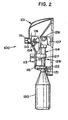
- a bottle 120 includes a neck 121, and a receiving aperture 122 configured and arranged to accept the neck 121 of the bottle 120.
- the receiving aperture 122 surrounds the conduit 125. When the conduit 125 is placed within the bottle 120, the neck 121 fits within the receiving aperture 122 to activate the actuator 115 thereby dispensing use solution into the bottle 120.
- the actuator 115 is in a first position 131 wherein the actuator 115 is not activating the activation switch 108 and the activation switch 108 is in a first state.
- the actuator is in a second position 132 wherein the actuator 115 is activating the activation switch 108 and the activation switch 108 is in a second state.
- the dispenser 100 includes both button-activated and bottle-activated dispensing options that automatically dilute and dispense cleaning and sanitizing solutions mixed to the correct ratios.
- button-activation the water valve 107 is activated by the activation switch 108 which is activated when the knob 111 is manually pressed in a lateral direction.
- the valve 107 allows water to flow through the venturi in the aspirator 114 and the aspirator 114 then concurrently draws in a concentrated product.
- the water mixes with the concentrated product within the aspirator 114 to the correct ratio to form a use solution.
- the use solution is then dispensed through the use solution outlet 128 and the conduit 125 into a container such as a mop bucket.
- the conduit 125 is placed inside the bottle 120 and the bottle neck 121 is inserted into the receiving aperture 122. This is shown in Figure 2 .
- the bottle 120 is then moved in a first, upward direction A to contact the second end 115d of the slide actuator 115.
- the bottle 120 pushes against the second end 115d and moves the slide actuator 115 upward.
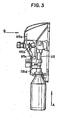
- the guide member 109 remains stationary and slides within the slot 116 along the angled portion 115b.
- the flange member 109a of the guide member 109 contacts the angled portion 115b.
- the angled portion 115b pushes against the flange member 109a and as the slide actuator 115 moves upward the guide member 109 is pressed inward in the second, lateral direction B thereby activating the activation switch 108.
- the angled portion 1115b pushes the activation switch 108 in a second, lateral direction B, and the activation switch 108 in turn activates the valve 107.
- Figure 3 This is shown in Figure 3 .
- the guide member 109 extends through the slot 116, the slot 116 does not interfere with the guide member 109 as the actuator 115 moves upward and downward.
Abstract
Claims (3)
- Distributeur (100) pour distribuer un produit concentré dans un récipient ou un seau,
le distributeur (100) comportant un aspirateur (114) possédant une entrée de diluant liquide (126), une entrée de produit concentré (127) et une sortie de solution d'utilisation (128),
une soupape (107) reliée fonctionnellement à l'aspirateur (114), la soupape (107) régulant le débit de diluant liquide à partir d'une source de diluant liquide jusqu'à l'entrée de diluant liquide (126),
un commutateur d'activation (108) possédant une partie d'extrémité et étant relié fonctionnellement à la soupape (107), le commutateur d'activation (108) commandant la soupape (107), le commutateur d'activation (108) pouvant adopter un premier état non activé avec la soupape (107) fermée et un deuxième état activé avec la soupape (107) ouverte, et
un actionneur coulissant (115), l'actionneur coulissant (115) comprenant une première extrémité (115a), une partie de prolongement (115c), une partie inclinée (115b) reliant la première extrémité (115a) et la partie de prolongement (115c) l'une à l'autre, et une deuxième extrémité (115d) reliée fonctionnellement à la partie de prolongement (115c) et s'étendant à partir de cette dernière,
la deuxième extrémité (115d) étant configurée et agencée pour être mise en contact avec un récipient (120) lorsqu'un tel récipient (120) est fixé à la sortie de solution d'utilisation (128), l'actionneur coulissant (115) pouvant adopter une première position dans laquelle le commutateur d'activation (108) est dans le premier état non activé, et une deuxième position dans laquelle la partie inclinée (115b) est en contact avec le commutateur d'activation (108) et déplace le commutateur d'activation (108) jusqu'au deuxième état activé, ladite deuxième position (132) se produisant lorsque le récipient (120) est déplacé vers le haut par rapport au commutateur d'activation (108),
caractérisé en ce que
la partie d'extrémité du commutateur d'activation (108) est munie d'un organe de guidage (109) relié fonctionnellement au commutateur d'activation (108),
l'organe de guidage (109) comportant un organe de rebord (109a) qui est en contact avec la partie inclinée (115b) de l'actionneur coulissant (115), l'organe de rebord (109a) de l'organe de guidage (109) se déplaçant le long de la partie inclinée (115b) de l'actionneur coulissant (115) lorsque le déplacement de l'actionneur coulissant (115) entre la première position (133) et la deuxième position (132) se produit, de telle sorte que le commutateur d'activation (108) soit déplacé pour adopter le deuxième état avec la soupape (107) ouverte,
un bouton (111) est relié fonctionnellement à la partie d'extrémité du commutateur d'activation (108) et comprend un bouton-poussoir pour activer le commutateur d'activation (108) lorsqu'il est enfoncé manuellement,
une fente (116) est pratiquée dans l'actionneur coulissant (115), la fente (116) s'étendant à partir de la première extrémité (115a) jusqu'à la partie inclinée (115b), la partie d'extrémité du commutateur d'activation (108) dotée de l'organe de guidage (109) s'étendant à travers la fente (116), la fente (116) n'entravant pas l'organe de guidage (109) lorsque le bouton (111) est poussé manuellement pour déplacer manuellement le commutateur d'activation (108) jusqu'au deuxième état. - Distributeur selon la revendication 1, caractérisé en ce
qu'un prolongateur (110) est relié fonctionnellement à l'organe de guidage (109) et le bouton (111) est relié fonctionnellement au prolongateur (110). - Distributeur selon la revendication 2, caractérisé en ce que
le distributeur (100) comporte un boîtier (101) doté d'une base (102) et d'un couvercle (103), le boîtier (101) loge la soupape (107) qui est activée par le commutateur d'activation (108), le couvercle (103) comporte une ouverture (104), le prolongateur (110) du commutateur d'activation (108) s'étend à travers l'ouverture (104) dans le couvercle (103).
Applications Claiming Priority (3)
| Application Number | Priority Date | Filing Date | Title |
|---|---|---|---|
| US266094 | 2002-10-04 | ||
| US10/266,094 US6789708B2 (en) | 2002-10-04 | 2002-10-04 | Combination push button and bottle lever for activating a water valve in a product dispenser |
| PCT/US2003/029592 WO2004033359A2 (fr) | 2002-10-04 | 2003-09-19 | Ensemble bouton poussoir et robinet de bouteille utile pour activer un robinet d'eau dans un distributeur de produit |
Publications (2)
| Publication Number | Publication Date |
|---|---|
| EP1554216A2 EP1554216A2 (fr) | 2005-07-20 |
| EP1554216B1 true EP1554216B1 (fr) | 2012-08-01 |
Family
ID=32042599
Family Applications (1)
| Application Number | Title | Priority Date | Filing Date |
|---|---|---|---|
| EP03752517A Expired - Lifetime EP1554216B1 (fr) | 2002-10-04 | 2003-09-19 | Ensemble bouton poussoir d'un distributeur de liquides |
Country Status (5)
| Country | Link |
|---|---|
| US (1) | US6789708B2 (fr) |
| EP (1) | EP1554216B1 (fr) |
| AU (1) | AU2003270804A1 (fr) |
| CA (1) | CA2499122C (fr) |
| WO (1) | WO2004033359A2 (fr) |
Families Citing this family (12)
| Publication number | Priority date | Publication date | Assignee | Title |
|---|---|---|---|---|
| AU2006264220B2 (en) * | 2005-06-28 | 2011-02-17 | Fluid Fashions Pty Ltd | Drink dispensing system |
| MX2008001752A (es) * | 2005-08-05 | 2008-04-07 | Johnson Diversey Inc | Aparato de abastecimiento. |
| AU2006280234B2 (en) | 2005-08-11 | 2011-05-26 | Diversey, Inc. | Two eductor / four-way selector valve assemby |
| US7516763B2 (en) | 2005-08-11 | 2009-04-14 | Johnsondiversey, Inc. | Multi-station liquid dispensing apparatus with automatic selection of proper flow rate |
| USD652674S1 (en) | 2005-08-12 | 2012-01-24 | Diversey, Inc. | Multi-station liquid dispensing apparatus |
| AU2008231376B2 (en) * | 2007-03-27 | 2012-12-20 | S. C. Johnson & Son, Inc. | Handheld device for dispensing fluids |
| GB2451446A (en) * | 2007-07-30 | 2009-02-04 | Packaging Innovation Ltd | Hand held sprayer with dump valve |
| DE102008002957A1 (de) * | 2008-07-22 | 2010-01-28 | Evonik Stockhausen Gmbh | Spendersystem für die portionsweise Ausgabe pastöser, flüssiger, gasförmiger und/oder geschäumter Medien |
| US8550302B1 (en) * | 2012-05-07 | 2013-10-08 | Rodney Laible | Wall mounted dispenser |
| US8939322B2 (en) * | 2012-05-07 | 2015-01-27 | Rodney Laible | Wall mounted dispenser |
| US10731768B2 (en) | 2016-10-12 | 2020-08-04 | Ecolab Usa Inc. | Systems and methods for manifold valves |
| EP3810862B1 (fr) | 2018-06-21 | 2023-01-25 | Husqvarna Ab | Soupape à culbuteur |
Family Cites Families (10)
| Publication number | Priority date | Publication date | Assignee | Title |
|---|---|---|---|---|
| US3438551A (en) | 1967-05-17 | 1969-04-15 | Brice Belisle | Dispenser combination for liquids |
| US4685596A (en) | 1986-04-23 | 1987-08-11 | Risdon Corporation | Fluid dispenser |
| CH677092A5 (en) | 1988-07-29 | 1991-04-15 | Essilor Int | Manual dispenser for small vol. of sterile liquids - includes flexible bag holding liq. which collapses as liq. is removed to prevent ingress of non-sterile ambient air |
| US5584327A (en) * | 1994-07-06 | 1996-12-17 | Ecolab Inc. | Method and apparatus for storing and dispensing chemical solutions |
| US5597019A (en) * | 1995-03-30 | 1997-01-28 | Ecolab Inc. | Dilution system for filling spray bottles |
| US5651398A (en) * | 1996-03-29 | 1997-07-29 | Ecolab Inc. | Chemical solution filling system |
| US5832972A (en) | 1996-07-26 | 1998-11-10 | Ecolab Inc. | Dilution dispensing system with product lock-out |
| US6279836B1 (en) | 1998-03-02 | 2001-08-28 | Ecolab Inc. | Portable unit and wall unit dispensers and method of dispensing with timer |
| US6105633A (en) * | 1999-07-02 | 2000-08-22 | Ecolab Inc. | Liquid dispenser |
| US6439272B1 (en) * | 2000-04-05 | 2002-08-27 | Keene Sanitary Supply, Inc. | Tamper-proof chemical dispensing device for high security environments |
-
2002
- 2002-10-04 US US10/266,094 patent/US6789708B2/en not_active Expired - Lifetime
-
2003
- 2003-09-19 CA CA2499122A patent/CA2499122C/fr not_active Expired - Lifetime
- 2003-09-19 WO PCT/US2003/029592 patent/WO2004033359A2/fr not_active Application Discontinuation
- 2003-09-19 AU AU2003270804A patent/AU2003270804A1/en not_active Abandoned
- 2003-09-19 EP EP03752517A patent/EP1554216B1/fr not_active Expired - Lifetime
Also Published As
| Publication number | Publication date |
|---|---|
| WO2004033359A2 (fr) | 2004-04-22 |
| AU2003270804A1 (en) | 2004-05-04 |
| WO2004033359B1 (fr) | 2004-08-12 |
| EP1554216A2 (fr) | 2005-07-20 |
| AU2003270804A8 (en) | 2004-05-04 |
| US20040065673A1 (en) | 2004-04-08 |
| US6789708B2 (en) | 2004-09-14 |
| CA2499122A1 (fr) | 2004-04-22 |
| WO2004033359A3 (fr) | 2004-06-03 |
| CA2499122C (fr) | 2012-05-15 |
Similar Documents
| Publication | Publication Date | Title |
|---|---|---|
| US9809443B2 (en) | Multi-station liquid dispensing apparatus with automatic selection of proper flow rate | |
| JP4607404B2 (ja) | 洗浄溶液希釈分取システム | |
| AU718738B2 (en) | Dilution dispensing system with product lock-out | |
| EP1554216B1 (fr) | Ensemble bouton poussoir d'un distributeur de liquides | |
| US6105633A (en) | Liquid dispenser | |
| US3863843A (en) | Anti-back siphoning water supply valve and mixer | |
| EP0828567B1 (fr) | Systeme de dosage variable a deux pistons | |
| EP1339634A2 (fr) | Mecanisme de securite pour appareil distributeur | |
| US6607174B2 (en) | Dispensing apparatus with in-line actuator | |
| CA2465154C (fr) | Systeme de distribution d'une solution avec dispositif de verrouillage | |
| MXPA97005680A (en) | Dilution system with produ closure |
Legal Events
| Date | Code | Title | Description |
|---|---|---|---|
| PUAI | Public reference made under article 153(3) epc to a published international application that has entered the european phase |
Free format text: ORIGINAL CODE: 0009012 |
|
| 17P | Request for examination filed |
Effective date: 20050318 |
|
| AK | Designated contracting states |
Kind code of ref document: A2 Designated state(s): AT BE BG CH CY CZ DE DK EE ES FI FR GB GR HU IE IT LI LU MC NL PT RO SE SI SK TR |
|
| AX | Request for extension of the european patent |
Extension state: AL LT LV MK |
|
| DAX | Request for extension of the european patent (deleted) | ||
| 17Q | First examination report despatched |
Effective date: 20101111 |
|
| REG | Reference to a national code |
Ref country code: DE Ref legal event code: R079 Ref document number: 60341679 Country of ref document: DE Free format text: PREVIOUS MAIN CLASS: B67D0005060000 Ipc: B67D0007060000 |
|
| GRAP | Despatch of communication of intention to grant a patent |
Free format text: ORIGINAL CODE: EPIDOSNIGR1 |
|
| RIC1 | Information provided on ipc code assigned before grant |
Ipc: B67D 7/06 20100101AFI20120215BHEP |
|
| GRAS | Grant fee paid |
Free format text: ORIGINAL CODE: EPIDOSNIGR3 |
|
| GRAA | (expected) grant |
Free format text: ORIGINAL CODE: 0009210 |
|
| AK | Designated contracting states |
Kind code of ref document: B1 Designated state(s): AT BE BG CH CY CZ DE DK EE ES FI FR GB GR HU IE IT LI LU MC NL PT RO SE SI SK TR |
|
| REG | Reference to a national code |
Ref country code: GB Ref legal event code: FG4D |
|
| REG | Reference to a national code |
Ref country code: CH Ref legal event code: EP Ref country code: AT Ref legal event code: REF Ref document number: 568570 Country of ref document: AT Kind code of ref document: T Effective date: 20120815 |
|
| REG | Reference to a national code |
Ref country code: IE Ref legal event code: FG4D |
|
| REG | Reference to a national code |
Ref country code: DE Ref legal event code: R096 Ref document number: 60341679 Country of ref document: DE Effective date: 20120927 |
|
| REG | Reference to a national code |
Ref country code: NL Ref legal event code: VDEP Effective date: 20120801 |
|
| REG | Reference to a national code |
Ref country code: AT Ref legal event code: MK05 Ref document number: 568570 Country of ref document: AT Kind code of ref document: T Effective date: 20120801 |
|
| REG | Reference to a national code |
Ref country code: DE Ref legal event code: R082 Ref document number: 60341679 Country of ref document: DE Representative=s name: VON ROHR PATENTANWAELTE PARTNERSCHAFT, DE Ref country code: DE Ref legal event code: R082 Ref document number: 60341679 Country of ref document: DE Representative=s name: VON ROHR PATENTANWAELTE PARTNERSCHAFT MBB, DE |
|
| PG25 | Lapsed in a contracting state [announced via postgrant information from national office to epo] |
Ref country code: CY Free format text: LAPSE BECAUSE OF FAILURE TO SUBMIT A TRANSLATION OF THE DESCRIPTION OR TO PAY THE FEE WITHIN THE PRESCRIBED TIME-LIMIT Effective date: 20120801 Ref country code: AT Free format text: LAPSE BECAUSE OF FAILURE TO SUBMIT A TRANSLATION OF THE DESCRIPTION OR TO PAY THE FEE WITHIN THE PRESCRIBED TIME-LIMIT Effective date: 20120801 Ref country code: FI Free format text: LAPSE BECAUSE OF FAILURE TO SUBMIT A TRANSLATION OF THE DESCRIPTION OR TO PAY THE FEE WITHIN THE PRESCRIBED TIME-LIMIT Effective date: 20120801 |
|
| PG25 | Lapsed in a contracting state [announced via postgrant information from national office to epo] |
Ref country code: BE Free format text: LAPSE BECAUSE OF FAILURE TO SUBMIT A TRANSLATION OF THE DESCRIPTION OR TO PAY THE FEE WITHIN THE PRESCRIBED TIME-LIMIT Effective date: 20120801 Ref country code: PT Free format text: LAPSE BECAUSE OF FAILURE TO SUBMIT A TRANSLATION OF THE DESCRIPTION OR TO PAY THE FEE WITHIN THE PRESCRIBED TIME-LIMIT Effective date: 20121203 Ref country code: GR Free format text: LAPSE BECAUSE OF FAILURE TO SUBMIT A TRANSLATION OF THE DESCRIPTION OR TO PAY THE FEE WITHIN THE PRESCRIBED TIME-LIMIT Effective date: 20121102 Ref country code: SE Free format text: LAPSE BECAUSE OF FAILURE TO SUBMIT A TRANSLATION OF THE DESCRIPTION OR TO PAY THE FEE WITHIN THE PRESCRIBED TIME-LIMIT Effective date: 20120801 Ref country code: SI Free format text: LAPSE BECAUSE OF FAILURE TO SUBMIT A TRANSLATION OF THE DESCRIPTION OR TO PAY THE FEE WITHIN THE PRESCRIBED TIME-LIMIT Effective date: 20120801 |
|
| PG25 | Lapsed in a contracting state [announced via postgrant information from national office to epo] |
Ref country code: NL Free format text: LAPSE BECAUSE OF FAILURE TO SUBMIT A TRANSLATION OF THE DESCRIPTION OR TO PAY THE FEE WITHIN THE PRESCRIBED TIME-LIMIT Effective date: 20120801 |
|
| PG25 | Lapsed in a contracting state [announced via postgrant information from national office to epo] |
Ref country code: CZ Free format text: LAPSE BECAUSE OF FAILURE TO SUBMIT A TRANSLATION OF THE DESCRIPTION OR TO PAY THE FEE WITHIN THE PRESCRIBED TIME-LIMIT Effective date: 20120801 Ref country code: MC Free format text: LAPSE BECAUSE OF NON-PAYMENT OF DUE FEES Effective date: 20120930 Ref country code: DK Free format text: LAPSE BECAUSE OF FAILURE TO SUBMIT A TRANSLATION OF THE DESCRIPTION OR TO PAY THE FEE WITHIN THE PRESCRIBED TIME-LIMIT Effective date: 20120801 Ref country code: EE Free format text: LAPSE BECAUSE OF FAILURE TO SUBMIT A TRANSLATION OF THE DESCRIPTION OR TO PAY THE FEE WITHIN THE PRESCRIBED TIME-LIMIT Effective date: 20120801 Ref country code: RO Free format text: LAPSE BECAUSE OF FAILURE TO SUBMIT A TRANSLATION OF THE DESCRIPTION OR TO PAY THE FEE WITHIN THE PRESCRIBED TIME-LIMIT Effective date: 20120801 |
|
| REG | Reference to a national code |
Ref country code: CH Ref legal event code: PL |
|
| PG25 | Lapsed in a contracting state [announced via postgrant information from national office to epo] |
Ref country code: IT Free format text: LAPSE BECAUSE OF FAILURE TO SUBMIT A TRANSLATION OF THE DESCRIPTION OR TO PAY THE FEE WITHIN THE PRESCRIBED TIME-LIMIT Effective date: 20120801 Ref country code: SK Free format text: LAPSE BECAUSE OF FAILURE TO SUBMIT A TRANSLATION OF THE DESCRIPTION OR TO PAY THE FEE WITHIN THE PRESCRIBED TIME-LIMIT Effective date: 20120801 |
|
| PLBE | No opposition filed within time limit |
Free format text: ORIGINAL CODE: 0009261 |
|
| STAA | Information on the status of an ep patent application or granted ep patent |
Free format text: STATUS: NO OPPOSITION FILED WITHIN TIME LIMIT |
|
| REG | Reference to a national code |
Ref country code: IE Ref legal event code: MM4A |
|
| REG | Reference to a national code |
Ref country code: FR Ref legal event code: ST Effective date: 20130531 |
|
| 26N | No opposition filed |
Effective date: 20130503 |
|
| GBPC | Gb: european patent ceased through non-payment of renewal fee |
Effective date: 20121101 |
|
| PG25 | Lapsed in a contracting state [announced via postgrant information from national office to epo] |
Ref country code: BG Free format text: LAPSE BECAUSE OF FAILURE TO SUBMIT A TRANSLATION OF THE DESCRIPTION OR TO PAY THE FEE WITHIN THE PRESCRIBED TIME-LIMIT Effective date: 20121101 Ref country code: IE Free format text: LAPSE BECAUSE OF NON-PAYMENT OF DUE FEES Effective date: 20120919 Ref country code: LI Free format text: LAPSE BECAUSE OF NON-PAYMENT OF DUE FEES Effective date: 20120930 Ref country code: CH Free format text: LAPSE BECAUSE OF NON-PAYMENT OF DUE FEES Effective date: 20120930 |
|
| REG | Reference to a national code |
Ref country code: DE Ref legal event code: R097 Ref document number: 60341679 Country of ref document: DE Effective date: 20130503 |
|
| PG25 | Lapsed in a contracting state [announced via postgrant information from national office to epo] |
Ref country code: FR Free format text: LAPSE BECAUSE OF NON-PAYMENT OF DUE FEES Effective date: 20121001 |
|
| PG25 | Lapsed in a contracting state [announced via postgrant information from national office to epo] |
Ref country code: ES Free format text: LAPSE BECAUSE OF FAILURE TO SUBMIT A TRANSLATION OF THE DESCRIPTION OR TO PAY THE FEE WITHIN THE PRESCRIBED TIME-LIMIT Effective date: 20121112 |
|
| PG25 | Lapsed in a contracting state [announced via postgrant information from national office to epo] |
Ref country code: GB Free format text: LAPSE BECAUSE OF NON-PAYMENT OF DUE FEES Effective date: 20121101 |
|
| PG25 | Lapsed in a contracting state [announced via postgrant information from national office to epo] |
Ref country code: TR Free format text: LAPSE BECAUSE OF FAILURE TO SUBMIT A TRANSLATION OF THE DESCRIPTION OR TO PAY THE FEE WITHIN THE PRESCRIBED TIME-LIMIT Effective date: 20120801 |
|
| PG25 | Lapsed in a contracting state [announced via postgrant information from national office to epo] |
Ref country code: LU Free format text: LAPSE BECAUSE OF NON-PAYMENT OF DUE FEES Effective date: 20120919 |
|
| PG25 | Lapsed in a contracting state [announced via postgrant information from national office to epo] |
Ref country code: HU Free format text: LAPSE BECAUSE OF FAILURE TO SUBMIT A TRANSLATION OF THE DESCRIPTION OR TO PAY THE FEE WITHIN THE PRESCRIBED TIME-LIMIT Effective date: 20030919 |
|
| PGFP | Annual fee paid to national office [announced via postgrant information from national office to epo] |
Ref country code: DE Payment date: 20220609 Year of fee payment: 20 |
|
| REG | Reference to a national code |
Ref country code: DE Ref legal event code: R071 Ref document number: 60341679 Country of ref document: DE |