EP1554154B1 - Drivetrain for a motor vehicle, method for starting an internal combustion engine and method for generating electrical current - Google Patents
Drivetrain for a motor vehicle, method for starting an internal combustion engine and method for generating electrical current Download PDFInfo
- Publication number
- EP1554154B1 EP1554154B1 EP03750713A EP03750713A EP1554154B1 EP 1554154 B1 EP1554154 B1 EP 1554154B1 EP 03750713 A EP03750713 A EP 03750713A EP 03750713 A EP03750713 A EP 03750713A EP 1554154 B1 EP1554154 B1 EP 1554154B1
- Authority
- EP
- European Patent Office
- Prior art keywords
- electric machine
- drive train
- output shaft
- crankshaft
- shaft
- Prior art date
- Legal status (The legal status is an assumption and is not a legal conclusion. Google has not performed a legal analysis and makes no representation as to the accuracy of the status listed.)
- Expired - Lifetime
Links
Images


Classifications
-
- F—MECHANICAL ENGINEERING; LIGHTING; HEATING; WEAPONS; BLASTING
- F02—COMBUSTION ENGINES; HOT-GAS OR COMBUSTION-PRODUCT ENGINE PLANTS
- F02N—STARTING OF COMBUSTION ENGINES; STARTING AIDS FOR SUCH ENGINES, NOT OTHERWISE PROVIDED FOR
- F02N15/00—Other power-operated starting apparatus; Component parts, details, or accessories, not provided for in, or of interest apart from groups F02N5/00 - F02N13/00
- F02N15/02—Gearing between starting-engines and started engines; Engagement or disengagement thereof
- F02N15/022—Gearing between starting-engines and started engines; Engagement or disengagement thereof the starter comprising an intermediate clutch
- F02N15/025—Gearing between starting-engines and started engines; Engagement or disengagement thereof the starter comprising an intermediate clutch of the friction type
-
- B—PERFORMING OPERATIONS; TRANSPORTING
- B60—VEHICLES IN GENERAL
- B60K—ARRANGEMENT OR MOUNTING OF PROPULSION UNITS OR OF TRANSMISSIONS IN VEHICLES; ARRANGEMENT OR MOUNTING OF PLURAL DIVERSE PRIME-MOVERS IN VEHICLES; AUXILIARY DRIVES FOR VEHICLES; INSTRUMENTATION OR DASHBOARDS FOR VEHICLES; ARRANGEMENTS IN CONNECTION WITH COOLING, AIR INTAKE, GAS EXHAUST OR FUEL SUPPLY OF PROPULSION UNITS IN VEHICLES
- B60K6/00—Arrangement or mounting of plural diverse prime-movers for mutual or common propulsion, e.g. hybrid propulsion systems comprising electric motors and internal combustion engines
- B60K6/20—Arrangement or mounting of plural diverse prime-movers for mutual or common propulsion, e.g. hybrid propulsion systems comprising electric motors and internal combustion engines the prime-movers consisting of electric motors and internal combustion engines, e.g. HEVs
- B60K6/42—Arrangement or mounting of plural diverse prime-movers for mutual or common propulsion, e.g. hybrid propulsion systems comprising electric motors and internal combustion engines the prime-movers consisting of electric motors and internal combustion engines, e.g. HEVs characterised by the architecture of the hybrid electric vehicle
- B60K6/48—Parallel type
-
- B—PERFORMING OPERATIONS; TRANSPORTING
- B60—VEHICLES IN GENERAL
- B60K—ARRANGEMENT OR MOUNTING OF PROPULSION UNITS OR OF TRANSMISSIONS IN VEHICLES; ARRANGEMENT OR MOUNTING OF PLURAL DIVERSE PRIME-MOVERS IN VEHICLES; AUXILIARY DRIVES FOR VEHICLES; INSTRUMENTATION OR DASHBOARDS FOR VEHICLES; ARRANGEMENTS IN CONNECTION WITH COOLING, AIR INTAKE, GAS EXHAUST OR FUEL SUPPLY OF PROPULSION UNITS IN VEHICLES
- B60K6/00—Arrangement or mounting of plural diverse prime-movers for mutual or common propulsion, e.g. hybrid propulsion systems comprising electric motors and internal combustion engines
- B60K6/20—Arrangement or mounting of plural diverse prime-movers for mutual or common propulsion, e.g. hybrid propulsion systems comprising electric motors and internal combustion engines the prime-movers consisting of electric motors and internal combustion engines, e.g. HEVs
- B60K6/50—Architecture of the driveline characterised by arrangement or kind of transmission units
- B60K6/54—Transmission for changing ratio
- B60K6/547—Transmission for changing ratio the transmission being a stepped gearing
-
- F—MECHANICAL ENGINEERING; LIGHTING; HEATING; WEAPONS; BLASTING
- F02—COMBUSTION ENGINES; HOT-GAS OR COMBUSTION-PRODUCT ENGINE PLANTS
- F02N—STARTING OF COMBUSTION ENGINES; STARTING AIDS FOR SUCH ENGINES, NOT OTHERWISE PROVIDED FOR
- F02N11/00—Starting of engines by means of electric motors
- F02N11/04—Starting of engines by means of electric motors the motors being associated with current generators
-
- F—MECHANICAL ENGINEERING; LIGHTING; HEATING; WEAPONS; BLASTING
- F02—COMBUSTION ENGINES; HOT-GAS OR COMBUSTION-PRODUCT ENGINE PLANTS
- F02N—STARTING OF COMBUSTION ENGINES; STARTING AIDS FOR SUCH ENGINES, NOT OTHERWISE PROVIDED FOR
- F02N15/00—Other power-operated starting apparatus; Component parts, details, or accessories, not provided for in, or of interest apart from groups F02N5/00 - F02N13/00
- F02N15/006—Assembling or mounting of starting devices
-
- B—PERFORMING OPERATIONS; TRANSPORTING
- B60—VEHICLES IN GENERAL
- B60K—ARRANGEMENT OR MOUNTING OF PROPULSION UNITS OR OF TRANSMISSIONS IN VEHICLES; ARRANGEMENT OR MOUNTING OF PLURAL DIVERSE PRIME-MOVERS IN VEHICLES; AUXILIARY DRIVES FOR VEHICLES; INSTRUMENTATION OR DASHBOARDS FOR VEHICLES; ARRANGEMENTS IN CONNECTION WITH COOLING, AIR INTAKE, GAS EXHAUST OR FUEL SUPPLY OF PROPULSION UNITS IN VEHICLES
- B60K6/00—Arrangement or mounting of plural diverse prime-movers for mutual or common propulsion, e.g. hybrid propulsion systems comprising electric motors and internal combustion engines
- B60K6/20—Arrangement or mounting of plural diverse prime-movers for mutual or common propulsion, e.g. hybrid propulsion systems comprising electric motors and internal combustion engines the prime-movers consisting of electric motors and internal combustion engines, e.g. HEVs
- B60K6/22—Arrangement or mounting of plural diverse prime-movers for mutual or common propulsion, e.g. hybrid propulsion systems comprising electric motors and internal combustion engines the prime-movers consisting of electric motors and internal combustion engines, e.g. HEVs characterised by apparatus, components or means specially adapted for HEVs
- B60K6/26—Arrangement or mounting of plural diverse prime-movers for mutual or common propulsion, e.g. hybrid propulsion systems comprising electric motors and internal combustion engines the prime-movers consisting of electric motors and internal combustion engines, e.g. HEVs characterised by apparatus, components or means specially adapted for HEVs characterised by the motors or the generators
- B60K2006/268—Electric drive motor starts the engine, i.e. used as starter motor
-
- B—PERFORMING OPERATIONS; TRANSPORTING
- B60—VEHICLES IN GENERAL
- B60K—ARRANGEMENT OR MOUNTING OF PROPULSION UNITS OR OF TRANSMISSIONS IN VEHICLES; ARRANGEMENT OR MOUNTING OF PLURAL DIVERSE PRIME-MOVERS IN VEHICLES; AUXILIARY DRIVES FOR VEHICLES; INSTRUMENTATION OR DASHBOARDS FOR VEHICLES; ARRANGEMENTS IN CONNECTION WITH COOLING, AIR INTAKE, GAS EXHAUST OR FUEL SUPPLY OF PROPULSION UNITS IN VEHICLES
- B60K6/00—Arrangement or mounting of plural diverse prime-movers for mutual or common propulsion, e.g. hybrid propulsion systems comprising electric motors and internal combustion engines
- B60K6/20—Arrangement or mounting of plural diverse prime-movers for mutual or common propulsion, e.g. hybrid propulsion systems comprising electric motors and internal combustion engines the prime-movers consisting of electric motors and internal combustion engines, e.g. HEVs
- B60K6/42—Arrangement or mounting of plural diverse prime-movers for mutual or common propulsion, e.g. hybrid propulsion systems comprising electric motors and internal combustion engines the prime-movers consisting of electric motors and internal combustion engines, e.g. HEVs characterised by the architecture of the hybrid electric vehicle
- B60K6/48—Parallel type
- B60K2006/4816—Electric machine connected or connectable to gearbox internal shaft
-
- F—MECHANICAL ENGINEERING; LIGHTING; HEATING; WEAPONS; BLASTING
- F16—ENGINEERING ELEMENTS AND UNITS; GENERAL MEASURES FOR PRODUCING AND MAINTAINING EFFECTIVE FUNCTIONING OF MACHINES OR INSTALLATIONS; THERMAL INSULATION IN GENERAL
- F16H—GEARING
- F16H3/00—Toothed gearings for conveying rotary motion with variable gear ratio or for reversing rotary motion
- F16H3/02—Toothed gearings for conveying rotary motion with variable gear ratio or for reversing rotary motion without gears having orbital motion
- F16H3/08—Toothed gearings for conveying rotary motion with variable gear ratio or for reversing rotary motion without gears having orbital motion exclusively or essentially with continuously meshing gears, that can be disengaged from their shafts
- F16H2003/0818—Toothed gearings for conveying rotary motion with variable gear ratio or for reversing rotary motion without gears having orbital motion exclusively or essentially with continuously meshing gears, that can be disengaged from their shafts comprising means for power-shifting
-
- F—MECHANICAL ENGINEERING; LIGHTING; HEATING; WEAPONS; BLASTING
- F16—ENGINEERING ELEMENTS AND UNITS; GENERAL MEASURES FOR PRODUCING AND MAINTAINING EFFECTIVE FUNCTIONING OF MACHINES OR INSTALLATIONS; THERMAL INSULATION IN GENERAL
- F16H—GEARING
- F16H2200/00—Transmissions for multiple ratios
- F16H2200/003—Transmissions for multiple ratios characterised by the number of forward speeds
- F16H2200/0034—Transmissions for multiple ratios characterised by the number of forward speeds the gear ratios comprising two forward speeds
-
- F—MECHANICAL ENGINEERING; LIGHTING; HEATING; WEAPONS; BLASTING
- F16—ENGINEERING ELEMENTS AND UNITS; GENERAL MEASURES FOR PRODUCING AND MAINTAINING EFFECTIVE FUNCTIONING OF MACHINES OR INSTALLATIONS; THERMAL INSULATION IN GENERAL
- F16H—GEARING
- F16H2200/00—Transmissions for multiple ratios
- F16H2200/003—Transmissions for multiple ratios characterised by the number of forward speeds
- F16H2200/0052—Transmissions for multiple ratios characterised by the number of forward speeds the gear ratios comprising six forward speeds
-
- F—MECHANICAL ENGINEERING; LIGHTING; HEATING; WEAPONS; BLASTING
- F16—ENGINEERING ELEMENTS AND UNITS; GENERAL MEASURES FOR PRODUCING AND MAINTAINING EFFECTIVE FUNCTIONING OF MACHINES OR INSTALLATIONS; THERMAL INSULATION IN GENERAL
- F16H—GEARING
- F16H3/00—Toothed gearings for conveying rotary motion with variable gear ratio or for reversing rotary motion
- F16H3/02—Toothed gearings for conveying rotary motion with variable gear ratio or for reversing rotary motion without gears having orbital motion
- F16H3/08—Toothed gearings for conveying rotary motion with variable gear ratio or for reversing rotary motion without gears having orbital motion exclusively or essentially with continuously meshing gears, that can be disengaged from their shafts
- F16H3/087—Toothed gearings for conveying rotary motion with variable gear ratio or for reversing rotary motion without gears having orbital motion exclusively or essentially with continuously meshing gears, that can be disengaged from their shafts characterised by the disposition of the gears
- F16H3/089—Toothed gearings for conveying rotary motion with variable gear ratio or for reversing rotary motion without gears having orbital motion exclusively or essentially with continuously meshing gears, that can be disengaged from their shafts characterised by the disposition of the gears all of the meshing gears being supported by a pair of parallel shafts, one being the input shaft and the other the output shaft, there being no countershaft involved
-
- F—MECHANICAL ENGINEERING; LIGHTING; HEATING; WEAPONS; BLASTING
- F16—ENGINEERING ELEMENTS AND UNITS; GENERAL MEASURES FOR PRODUCING AND MAINTAINING EFFECTIVE FUNCTIONING OF MACHINES OR INSTALLATIONS; THERMAL INSULATION IN GENERAL
- F16H—GEARING
- F16H3/00—Toothed gearings for conveying rotary motion with variable gear ratio or for reversing rotary motion
- F16H3/02—Toothed gearings for conveying rotary motion with variable gear ratio or for reversing rotary motion without gears having orbital motion
- F16H3/08—Toothed gearings for conveying rotary motion with variable gear ratio or for reversing rotary motion without gears having orbital motion exclusively or essentially with continuously meshing gears, that can be disengaged from their shafts
- F16H3/087—Toothed gearings for conveying rotary motion with variable gear ratio or for reversing rotary motion without gears having orbital motion exclusively or essentially with continuously meshing gears, that can be disengaged from their shafts characterised by the disposition of the gears
- F16H3/091—Toothed gearings for conveying rotary motion with variable gear ratio or for reversing rotary motion without gears having orbital motion exclusively or essentially with continuously meshing gears, that can be disengaged from their shafts characterised by the disposition of the gears including a single countershaft
- F16H3/0915—Toothed gearings for conveying rotary motion with variable gear ratio or for reversing rotary motion without gears having orbital motion exclusively or essentially with continuously meshing gears, that can be disengaged from their shafts characterised by the disposition of the gears including a single countershaft with coaxial input and output shafts
-
- F—MECHANICAL ENGINEERING; LIGHTING; HEATING; WEAPONS; BLASTING
- F16—ENGINEERING ELEMENTS AND UNITS; GENERAL MEASURES FOR PRODUCING AND MAINTAINING EFFECTIVE FUNCTIONING OF MACHINES OR INSTALLATIONS; THERMAL INSULATION IN GENERAL
- F16H—GEARING
- F16H3/00—Toothed gearings for conveying rotary motion with variable gear ratio or for reversing rotary motion
- F16H3/02—Toothed gearings for conveying rotary motion with variable gear ratio or for reversing rotary motion without gears having orbital motion
- F16H3/08—Toothed gearings for conveying rotary motion with variable gear ratio or for reversing rotary motion without gears having orbital motion exclusively or essentially with continuously meshing gears, that can be disengaged from their shafts
- F16H3/12—Toothed gearings for conveying rotary motion with variable gear ratio or for reversing rotary motion without gears having orbital motion exclusively or essentially with continuously meshing gears, that can be disengaged from their shafts with means for synchronisation not incorporated in the clutches
- F16H3/126—Toothed gearings for conveying rotary motion with variable gear ratio or for reversing rotary motion without gears having orbital motion exclusively or essentially with continuously meshing gears, that can be disengaged from their shafts with means for synchronisation not incorporated in the clutches using an electric drive
-
- Y—GENERAL TAGGING OF NEW TECHNOLOGICAL DEVELOPMENTS; GENERAL TAGGING OF CROSS-SECTIONAL TECHNOLOGIES SPANNING OVER SEVERAL SECTIONS OF THE IPC; TECHNICAL SUBJECTS COVERED BY FORMER USPC CROSS-REFERENCE ART COLLECTIONS [XRACs] AND DIGESTS
- Y02—TECHNOLOGIES OR APPLICATIONS FOR MITIGATION OR ADAPTATION AGAINST CLIMATE CHANGE
- Y02T—CLIMATE CHANGE MITIGATION TECHNOLOGIES RELATED TO TRANSPORTATION
- Y02T10/00—Road transport of goods or passengers
- Y02T10/60—Other road transportation technologies with climate change mitigation effect
- Y02T10/62—Hybrid vehicles
-
- Y—GENERAL TAGGING OF NEW TECHNOLOGICAL DEVELOPMENTS; GENERAL TAGGING OF CROSS-SECTIONAL TECHNOLOGIES SPANNING OVER SEVERAL SECTIONS OF THE IPC; TECHNICAL SUBJECTS COVERED BY FORMER USPC CROSS-REFERENCE ART COLLECTIONS [XRACs] AND DIGESTS
- Y10—TECHNICAL SUBJECTS COVERED BY FORMER USPC
- Y10S—TECHNICAL SUBJECTS COVERED BY FORMER USPC CROSS-REFERENCE ART COLLECTIONS [XRACs] AND DIGESTS
- Y10S903/00—Hybrid electric vehicles, HEVS
- Y10S903/902—Prime movers comprising electrical and internal combustion motors
- Y10S903/903—Prime movers comprising electrical and internal combustion motors having energy storing means, e.g. battery, capacitor
- Y10S903/946—Characterized by control of driveline clutch
Definitions
- the present invention further relates to a method for starting an internal combustion engine of a motor vehicle and for initiating the starting of the motor vehicle.
- the present invention relates to a method for generating electric current by an electric machine which is driven by an internal combustion engine of a motor vehicle while the motor vehicle is stationary.
- an electric machine As a starter generator between the internal combustion engine and the friction clutch.
- the electric machine can be operated with open friction clutch as a motor for starting the engine.
- the electric machine can be used as a generator for supplying the vehicle electrical system. See Bosch Automotive Handbook, 24th Edition, page 932.
- An electric machine in the drive train can also be used for other functions.
- an electric machine in the drive train is connected to at least one transmission shaft of a stepped transmission and serves to decelerate or accelerate the shaft for the purpose of synchronization to the clutch of a gear to be engaged.
- the clutches on a mechanical synchronization can be dispensed with, so that the clutches can be formed as a simple jaw clutches or the like.
- an electrical machine arranged in the gearbox allows both a traction and a recuperation, but often do not allow operation of the electric machine as a starter generator, as to close the internal combustion engine usually not only the friction clutch, but also at least one of the clutches of the stepped transmission is.
- the clutch for the third gear is designed as Reibschaltkupplung.
- a hybrid drive for vehicles is known in which a manual transmission is divided into two partial transmissions.
- One of the partial transmissions is connected to an electrical machine.
- the other partial transmission is selectively drive-connected with an internal combustion engine and / or with the electric machine.
- the output shaft of the electric machine is connected to a shaft of the stepped transmission.
- DE 295 02 906 U1 also discloses a hybrid drive, wherein the rotor of an electric machine is rotatably mounted on the crankshaft of the internal combustion engine. By means of a first separating clutch, the rotor can be connected to the crankshaft. By means of a second separating clutch, the rotor can be connected to a transmission input shaft.
- a dual-clutch transmission which has two partial transmissions. At least one of the gears can be connected to an electrical machine.
- the problem underlying the present invention is to provide an improved powertrain for a motor vehicle, an improved starting method for an internal combustion engine, and an improved method for generating electric power.
- steps b) and c) can each take place before or after step a).
- the step d) can take place simultaneously with step c).
- the inventive allows Powertrain to start the engine or to operate the electric machine in generator mode, without the friction clutch must be closed.
- the drive train according to the invention is in particular an automated drive train, in which the essential functions of the stepped transmission and the friction clutch are actuated by actuators.
- the drive train should be suitable in particular for those motor vehicles in which the internal combustion engine is the main engine and the electric machine merely performs additional functions and does not represent an equivalent drive source.
- the starting process can be faster in both modes, which contributes to the acceptance of the entire system.
- the driver will feel no difference to a normal vehicle.
- a creep function hill-holding function
- the electric machine is arranged outside of a housing of the stepped transmission and has an output shaft which extends into the interior of the housing via a shaft seal.
- connection of the output shaft of the electric machine with the output shaft of the stepped transmission or the crankshaft can then take place within the transmission housing.
- conventional clutches can then be used.
- the output shaft of the electric machine is arranged parallel to the output shaft of the stepped transmission.
- the space available for the drive train in the vehicle space can be exploited particularly favorable.
- connection of the electric machine to the output shaft of the stepped transmission can therefore be done by means of standardized and therefore inexpensive to produce elements inside the stepped transmission.
- the clutch is a synchronized clutch.
- the electric machine can connect largely smoothly even at differential speeds to the output shaft of the stepped transmission.
- the output shaft of the electric machine is arranged parallel to the crankshaft of the internal combustion engine.
- the output shaft of the electric machine is connectable via a clutch to the crankshaft and when the clutch is disposed within the housing of the stepped transmission.
- a standardized and maintenance-free clutch can be arranged in the interior of the transmission housing. In other words, it is not necessary to provide outside of the transmission switching means that require special maintenance or encapsulation.
- connection between the output shaft of the electric machine and the crankshaft via a shaft which is arranged parallel to the input shaft of the stepped transmission is also considered advantageous if the connection between the output shaft of the electric machine and the crankshaft via a shaft which is arranged parallel to the input shaft of the stepped transmission.
- connection between the output shaft of the electric machine and the crankshaft via a rotary member which is arranged concentrically to the input shaft of the stepped transmission.
- the rotary member is designed as a hollow shaft which is connected to the input member of the friction clutch and is arranged around the input shaft of the stepped transmission around.
- connection of the rotary member to the output shaft of the electric machine in the interior of the housing of the stepped transmission can be realized particularly favorable.
- the input shaft of the stepped transmission is designed as a hollow shaft and when the rotary member is mounted as a shaft within the input shaft.
- the rotary member structurally particularly easy to connect to the input member of the friction clutch.
- the rotary member is designed as a ring gear, which by means of a Sealed shaft seal against the housing of the stepped transmission and rotatably connected via at least one connected to the input member of the friction clutch driver with the crankshaft.
- connection between the output shaft of the electric machine and the ring gear via at least one traction mechanism is particularly advantageous if the connection between the output shaft of the electric machine and the ring gear via at least one traction mechanism.
- the traction mechanism can, for example, be a belt drive or a chain drive. By this measure weight can be saved compared to gear connections. Furthermore, this can limit the radial size of the transmission.
- the electric machine can be switched by means of a compact arrangement of the starter generator operation in the operation for power assistance.
- the clutch pack is additionally switched to idle, so that the output shaft of the electric machine idles.
- a first embodiment of a drive train according to the invention is generally designated 10.
- the drive train 10 can be mounted in a motor vehicle, not shown, which is driven by an internal combustion engine 12.
- the drive train 10 has a friction clutch 14 and a stepped transmission 16.
- the friction clutch 14 is designed as a starting and separating clutch and usually realized as a dry clutch. However, it can also be designed as a wet clutch.
- An input member of the friction clutch 14 is connected to a crankshaft 18 of the engine 12.
- An output member of the friction clutch 14 is connected to an input shaft 20 of the stepped transmission 16.
- An output shaft 22 of the stepped transmission 16 is connected via a differential, not shown, with drive wheels of the motor vehicle.
- the stepped transmission 16 is designed as a spur gear, with a countershaft 24, which is arranged in a conventional per se construction parallel to the output shaft 22.
- the step transmission 16 further comprises a plurality of wheelsets corresponding to a plurality of gear stages, of which in Fig. 1 for reasons of clarity, only one set of wheels 26 is shown.
- the wheelset 26 has a fixed wheel 28 which is rotatably connected to the output shaft 22, and a loose wheel 30 which is rotatably mounted on the countershaft 24.
- a shift clutch 32 shown schematically serves to selectively connect the idler gear 30 with the countershaft 24.
- the clutch 32 may be formed as a synchronizer clutch. However, it may also be an unsynchronized jaw clutch or the like.
- the drive train 10 has an electric machine 40.
- An output shaft 42 of the electric machine 40 is connected via a switchable wheelset 44 to the crankshaft 18 of the internal combustion engine 12.
- a clutch 43 which may be arranged for example on the output shaft 42.
- the output shaft 42 of the electric machine 40 is connected via a switchable wheelset 46 to the output shaft 22 of the stepped transmission 16.
- a clutch 48 is provided on the output shaft 42, which is designed to connect the wheel 46 in a form-fitting manner with the output shaft 42 of the electric machine 40.
- the electric machine 40 can be operated via the connection to the crankshaft 18 as a starter generator. To start the internal combustion engine 12, the clutch 43 is closed and the clutch 48 is opened and the friction clutch 14 is also opened. Subsequently, the electric machine is operated as a motor to drive and start the engine 12.
- the electric machine 40 When the internal combustion engine 12 is running, the electric machine 40 is operated as a generator and serves to supply the vehicle electrical system of the motor vehicle with voltage or to charge a battery, not shown, of the motor vehicle.
- the electric machine 40 When changing gear, the electric machine 40 can be used for traction assistance. In this case, the clutch 43 is released and the clutch 48 is closed. While the friction clutch 14 is open for laying out the head passage and engaging the target gear, the electric machine 40 can be operated as a motor so as to direct traction to the output shaft 22 of the stepped transmission 16.
- the electric machine 40 can be used with the gear engaged and the friction clutch 14 closed as a "booster" to the output power to the transmission output shaft 22 to increase.
- the booster operation can take place with the clutch 48 closed or even with the clutch 43 closed. In the latter case, torque flow then takes place via the respectively connected gear. This may be beneficial, especially in the lower gears.
- step transmission 16 already a gear for the starting process can be inserted.
- the friction clutch 14 can then be closed immediately to initiate the starting process.
- the process of starting the engine 12 and closing the friction clutch 14 may also be performed intersecting.
- the electric machine 40 can be used in overrun operation of the internal combustion engine 12 for energy recovery (recuperation), for which purpose the clutch 43 is opened and the clutch 48 is closed.
- the electric machine 40 as a maneuvering aid or traction aid.
- the friction clutch 14 and the clutch 43 are opened and the clutch 48 is closed to drive by means of the electric machine 40, the vehicle for the purpose of marshalling or stopping on a slope ("Hill Holder").
- the electric machine 40 can also be used for vibration damping of the drive train.
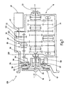
- a second embodiment of the drive train according to the invention is generally designated 54.
- the housing of the stepped transmission 16 is shown at 56 in FIG. It can be seen that the electric machine 40 is externally flanged to the housing 56, wherein the output shaft 42 is guided via a shaft seal 55 in the interior of the housing 56.
- auxiliary shaft 58 extends from the interior of the housing 56 via a shaft seal 57 from the other end of the housing 56 out.
- the secondary shaft 58 runs parallel to the transmission input shaft 20 and leads past the friction clutch 14.
- the stepped gear 16 is formed in the illustrated embodiment as a transverse gear, wherein the countershaft 24 simultaneously forms the output shaft 22 of the stepped gear 16.
- the protruding from the housing 56 part of the auxiliary shaft 58 is rotatably connected in the illustrated embodiment via a belt drive 62 with the crankshaft 18 of the engine 12.
- the output shaft 42 of the electric machine 40 is connected via a switchable by means of the clutch 48 wheelset 59 with the output shaft 22 of the stepped transmission 16.
- the wheelset 59 has an unspecified wheel which is rotatably mounted on the output shaft 42 of the electric machine 40, a rotatably mounted on the transmission input shaft 20 and a wheel rotatably fixed to the output shaft 22 wheel.
- an intermediate gear 64 is provided to reverse the direction of rotation.
- the output shaft 42 of the electric machine 40 is further connected by means of a clutch 60 with the secondary shaft 58.
- the clutches 48 and 60 are designed as a switching package, the output shaft 42 idles in a middle position of a unspecified shift sleeve and is not connected to the secondary shaft 58 with the transmission output shaft 22.
- the friction clutch 14 is also shown in greater detail.
- the friction clutch 14 has a flywheel 66 which is non-rotatably connected to the crankshaft 18.
- a clutch disc 68 is rotatably connected to the transmission input shaft 20.
- the clutch disc 68 is pressed by means of a disc spring or the like to the flywheel 66, wherein the plate spring is mounted on a clutch basket 67.
- the drive train 10 is preferably designed as an automated drive train, wherein the actuations of the various clutches 14, 43, 48, 32, 60 by means of suitable actuators, controlled by an unspecified control device.
- clutches 48, 60 in the interior of the transmission housing 56, these clutches can be constructed in a similar manner as the clutches 32 to the input and arranging the gear stages of the step transmission 16.
- a conventional electric machine can be used without special encapsulation.
- a modification of the drive train 54 of FIG. 2 is indicated generally at 70 in FIG.
- the wheelset 59 has no idler gear 64 for reversing the direction of rotation in this modification.
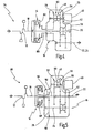
- FIG. 4 shows a third embodiment of a drive train 76 according to the invention.
- the output shaft 42 of the electric machine 40 reaching into the interior of the transmission housing 56 can be connected via a wheel set 78 to a secondary shaft 80 in the form of a hollow shaft.
- the hollow shaft 80 is rotatably connected to the clutch basket 82 in this embodiment, and thus rotationally fixed to the crankshaft 18th
- the transmission input shaft 20 extends through the hollow shaft 80 therethrough.
- This embodiment has over the drive train 54 has the advantage that the connection between the output shaft 42 of the electric machine 40 and crankshaft 18 via a rotary member (in the form of the hollow shaft 80) takes place, which is arranged concentrically to the transmission input shaft 20. Consequently, the space can be kept small in the radial direction. There is no outside of the friction clutch 14 personallyorderde wave necessary.
- FIG. 5 shows a further alternative embodiment of a drive train 88 according to the invention.
- the output shaft 42 of the electric machine 40 is connected via a gear set 92 with a secondary shaft 90 which is rotatably connected in extension of the crankshaft 18 with this.
- the transmission input shaft 94 is formed as a hollow shaft and surrounds the auxiliary shaft 90th
- the transmission input shaft 94 is connected via a Konstantenradsatz 96 with the countershaft 24 of the stepped transmission.
- the stepped transmission 16 of this embodiment is designed in longitudinal construction.
- FIG. 6 shows a fifth embodiment of the drive train 100 according to the invention.
- the auxiliary shaft 90 rotatably connected to the crankshaft 18 extends over the entire axial length of the stepped transmission 16 and is connected via a gear 102 with the output shaft 42 of the electric machine 40, which is arranged at the output end of the housing 56 is.
- the wheel sets 26 of the stepped transmission 16 are arranged on the transmission input shaft 94 designed as a hollow shaft.
- the connecting wheel set 92 is located at the transmission input end and the wheel sets 26 are mounted on the transmission output shaft 22 and the countershaft 24.
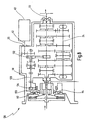
- FIG. 7 shows a sixth embodiment of the drive train 108 according to the invention.
- one or more drivers 112 are arranged on the side of the clutch basket 67 facing the stepped transmission 16.
- the drivers 112 are engaged with a ring gear 114 concentrically disposed about the clutch actuator 110 and rotatably supported on the housing 56 of the step transmission 16.
- the ring gear 114 is sealed via two shaft seals 116 and 117 to the transmission housing 56 and thus separates the interior of the housing 56 from the coupling side.
- a gear 118 is fixed, which meshes with a gear 119.
- the gear 119 is rotatably connected to a secondary shaft 120, which is arranged parallel to the transmission input shaft 20. Consequently, the auxiliary shaft 120 is rotatably connected to the crankshaft 18.
- the output shaft 42 of the electric machine 40 is connected via a gear set 122 to a second auxiliary shaft 123, which is arranged in extension of the first auxiliary shaft 120.
- a second auxiliary shaft 123 At the second auxiliary shaft 123, the switching package of clutch 48 and clutch 60 is mounted.
- the clutch 60 connects the auxiliary shafts 120, 123.
- the clutch 48 connects the auxiliary shaft 123 with a wheel 59th
- FIG. 8 shows a seventh embodiment of the drive train 130 according to the invention, which is largely identical to the drive train 108 of FIG. 7.
- the ring gear 114 is provided with a pulley 133 and connected via a belt drive 134 with the auxiliary shaft 120.
- a belt drive is also provided, which is generally designated 132 in FIG.
Landscapes
- Engineering & Computer Science (AREA)
- Chemical & Material Sciences (AREA)
- Combustion & Propulsion (AREA)
- Mechanical Engineering (AREA)
- General Engineering & Computer Science (AREA)
- Transportation (AREA)
- Arrangement Of Transmissions (AREA)
- Hybrid Electric Vehicles (AREA)
Description
Die vorliegende Erfindung betrifft einen Antriebsstrang für ein Kraftfahrzeug, das von einem Verbrennungsmotor angetrieben ist, mit:
- einer einzelnen Reibkupplung, die ein Eingangsglied und ein Ausgangsglied aufweist, wobei das Eingangsglied mit einer Kurbelwelle des Verbrennungsmotors zu verbinden ist;
- einem Stufengetriebe, das eine Eingangswelle, eine Mehrzahl von Radsätzen entsprechend einer Mehrzahl von Gangstufen und eine Abtriebswelle aufweist, wobei die Eingangswelle mit dem Ausgangsglied der Reibkupplung verbunden ist; und
- einer elektrischen Maschine, die über eine Kupplung mit der Abtriebswelle des Stufengetriebes verbindbar ist, um bei geöffneter oder geschlossener Reibkupplung Zugkraft auf die Abtriebswelle des Stufengetriebes leiten zu können, und die als Startergenerator mit der Kurbelwelle verbindbar ist, um den Verbrennungsmotor zu starten oder von dem Verbrennungsmotor angetrieben zu werden.
- a single friction clutch having an input member and an output member, the input member to be connected to a crankshaft of the internal combustion engine;
- a stepped transmission having an input shaft, a plurality of gear sets corresponding to a plurality of gear stages, and an output shaft, the input shaft being connected to the output member of the friction clutch; and
- an electric machine, which is connectable via a clutch to the output shaft of the stepped transmission to be able to conduct traction power to the output shaft of the stepped transmission with open or closed friction clutch, and which is connectable as a starter generator with the crankshaft to start the engine or of the Internal combustion engine to be driven.
Die vorliegende Erfindung betrifft ferner ein Verfahren zum Starten eines Verbrennungsmotors eines Kraftfahrzeuges und zum Einleiten des Anfahrens des Kraftfahrzeuges.The present invention further relates to a method for starting an internal combustion engine of a motor vehicle and for initiating the starting of the motor vehicle.
Schließlich betrifft die vorliegende Erfindung ein Verfahren zum Generieren von elektrischem Strom durch eine elektrische Maschine, die von einem Verbrennungsmotor eines Kraftfahrzeuges angetrieben wird, während das Kraftfahrzeug stillsteht.Finally, the present invention relates to a method for generating electric current by an electric machine which is driven by an internal combustion engine of a motor vehicle while the motor vehicle is stationary.
Es ist seit langem bekannt, in den Antriebsstrang eines verbrennungsmotor-getriebenen Kraftfahrzeuges eine elektrische Maschine zu integrieren. Dabei sind die Funktionen des Startens des Verbrennungsmotors und des Generierens von Strom für das Bordnetz herkömmlich durch zwei getrennte elektrische Maschinen realisiert, den Anlasser bzw. die Lichtmaschine.It has long been known to integrate an electric machine in the drive train of an internal combustion engine-powered motor vehicle. The functions of starting the internal combustion engine and generating electricity for the electrical system are conventionally realized by two separate electrical machines, the starter and the alternator.
Für Bordnetze des Kraftfahrzeuges mit höheren Nennspannungen (z. B. 42 Volt-Bordnetz) wird generell auch erwogen, zwischen Verbrennungsmotor und Reibkupplung eine elektrische Maschine als Startergenerator vorzusehen. Die elektrische Maschine kann bei geöffneter Reibkupplung als Motor zum Anlassen des Verbrennungsmotors betrieben werden. Bei laufendem Verbrennungsmotor kann die elektrische Maschine als Generator zum Speisen des Bordnetzes verwendet werden. Vergleiche Bosch Kraftfahrtechnisches Taschenbuch, 24. Auflage, Seite 932.For on-board systems of the motor vehicle with higher rated voltages (eg, 42 volt vehicle electrical system), it is generally also considered to provide an electric machine as a starter generator between the internal combustion engine and the friction clutch. The electric machine can be operated with open friction clutch as a motor for starting the engine. When the internal combustion engine is running, the electric machine can be used as a generator for supplying the vehicle electrical system. See Bosch Automotive Handbook, 24th Edition, page 932.
Eine elektrische Maschine im Antriebsstrang kann auch für andere Funktionen benutzt werden.An electric machine in the drive train can also be used for other functions.
So ist es bekannt, die elektrische Maschine bei einem starken Beschleunigungswunsch des Fahrers als "Booster" einzusetzen, so daß sich die Leistung des Verbrennungsmotors und die Leistung der elektrischen Maschine am Abtrieb addieren.So it is known to use the electric machine with a strong acceleration request of the driver as a "booster", so that add the power of the engine and the power of the electric machine at the output.
Ferner ist es möglich, die beim Bremsen des Fahrzeugs und beim Abschalten des Motors verbleibende Schwungenergie in elektrische Energie umzusetzen (Rekuperation). Die derart gewonnene Energie läßt sich zur Anfahrunterstützung nutzen.Furthermore, it is possible to convert the remaining during braking of the vehicle and when switching off the engine flywheel energy into electrical energy (recuperation). The energy thus obtained can be used for starting assistance.
Ferner ist es bekannt, eine elektrische Maschine der Abtriebsseite des Getriebes zuzuordnen, um die elektrische Maschine bei Gangwechseln dazu zu nutzen, während der Phasen geöffneter Reibkupplung Zugkraft auf die Abtriebswelle des Getriebes zu geben. Hierdurch wird eine Zugkraftunterstützung realisiert, die insbesondere bei sogenannten automatisierten Handschaltgetrieben Anwendung findet.Furthermore, it is known to associate an electric machine with the output side of the transmission in order to use the electric machine during gear changes during the phases of open friction clutch to give tractive force to the output shaft of the transmission. As a result, a traction assistance is realized, which is used in particular in so-called automated manual transmissions.
Eine weitere Funktion einer elektrischen Maschine im Antriebsstrang ist die aktive Synchronisation. Hierbei ist die elektrische Maschine mit wenigstens einer Getriebewelle eines Stufengetriebes verbunden und dient dazu, die Welle zum Zwecke der Synchronisation an der Schaltkupplung eines einzulegenden Ganges abzubremsen bzw. zu beschleunigen. Bei dieser Ausführungsform kann zumindest für einige Schaltkupplungen auf eine mechanische Synchronisierung verzichtet werden, so daß die Schaltkupplungen als einfache Klauenkupplungen oder ähnliches ausgebildet werden können.Another function of an electric machine in the drive train is the active synchronization. Here, the electric machine is connected to at least one transmission shaft of a stepped transmission and serves to decelerate or accelerate the shaft for the purpose of synchronization to the clutch of a gear to be engaged. In this embodiment, at least for some clutches on a mechanical synchronization can be dispensed with, so that the clutches can be formed as a simple jaw clutches or the like.
Schließlich ist es auch bekannt, daß das Abschalten des Verbrennungsmotors im Stillstand (beispielsweise bei einer Ampel) und das Wiederanlassen erst mit dem Anfahrwunsch erhebliche Brennstoffeinsparpotentiale in sich birgt.Finally, it is also known that the shutdown of the engine at standstill (for example, at a traffic light) and the restarting only with the start-up considerable fuel savings potential in itself.
Demzufolge ist es eine Wunschfunktion für integrierte elektrische Maschinen, einen solchen Direktstart nach dem Abschalten des Verbrennungsmotors zu unterstützen.Accordingly, it is a desire function for integrated electric machines to support such a direct start after the engine is shut down.
Die Druckschrift "Mögliche Anordnung des Startergenerators im Antriebsstrang" von Dr.-Ing. Wolfgang Reik, Tagungsband zur Fachtagung "E-Maschine im Antriebsstrang", 9. April 1999, offenbart eine Übersicht über die möglichen Anordnungen einer elektrischen Maschine im Antriebsstrang, und die mit der jeweiligen Anordnung verbundenen Vor- und Nachteile.The publication "Possible arrangement of the starter generator in the drive train" by Dr.-Ing. Wolfgang Reik, Proceedings to the conference "E-machine in the drive train", April 9, 1999, discloses an overview of the possible arrangements of an electric machine in the drive train, and associated with the respective arrangement advantages and disadvantages.
So hat beispielsweise eine Verbindung der elektrischen Maschine mit der Kurbelwelle des Verbrennungsmotors zwar den Vorteil, daß ein Direktstart möglich ist, eine Zugkraftunterstützung läßt sich jedoch nicht realisieren.For example, although a connection of the electric machine to the crankshaft of the internal combustion engine has the advantage that a direct start is possible, a traction assistance can not be realized.
Eine Anordnung zwischen Reibkupplung und Getriebe hat zwar den Vorteil, daß eine Rekuperation möglich ist, ein Direktstart ist jedoch ebensowenig möglich wie eine Zugkraftunterstützung.Although an arrangement between friction clutch and transmission has the advantage that a recuperation is possible, a direct start is just as possible as a traction assistance.
Eine im Getriebe angeordnete elektrische Maschine ermöglicht zwar sowohl eine Zugkraftunterstützung als auch eine Rekuperation, ermöglichst jedoch häufig keinen Betrieb der elektrischen Maschine als Startergenerator, da zum Antreiben des Verbrennungsmotors in der Regel nicht nur die Reibkupplung, sondern auch wenigstens eine der Schaltkupplungen des Stufengetriebes zu schließen ist.Although an electrical machine arranged in the gearbox allows both a traction and a recuperation, but often do not allow operation of the electric machine as a starter generator, as to close the internal combustion engine usually not only the friction clutch, but also at least one of the clutches of the stepped transmission is.
Aus "Integration automatisierter Schaltgetriebe mit E-Maschine" von Dr. Robert Fischer et al, Tagungsband zur Fachtagung "E-Maschine im Antriebsstrang", 9. April 1999 ist bekannt, eine elektrische Maschine im Antriebsstrang so anzuordnen, daß sie einerseits über eine Kupplung mit der Abtriebswelle des Stufengetriebes verbindbar ist und andererseits über eine Kupplung mit der Getriebeeingangswelle (im folgenden "Fischer-Lösung"). Diese Anordnung wird als besonders günstig betrachtet, da sie sowohl einen Startergeneratorbetrieb, eine Rekuperation als auch eine Lastschaltung mit Zugkraftunterstützung ermöglichst.From "Integration of automated manual transmissions with electric motor" by Dr. Ing. Robert Fischer et al, Proceedings to the conference "Electric motor in the drive train", April 9, 1999 is known to arrange an electric machine in the drive train so that it can be connected via a clutch to the output shaft of the stepped transmission and on the other hand via a coupling with the transmission input shaft (hereinafter "Fischer solution"). This arrangement is considered to be particularly favorable, since it allows both a starter generator operation, a recuperation and a load circuit with traction assistance.
Diese Variante des Standes der Technik wurde zur Bildung des Oberbegriffes des Anspruchs 1 herangezogen.This variant of the prior art was used to form the preamble of claim 1.
Ein Beispiel für einen Antriebsstrang, bei dem eine elektrische Maschine mit einer Welle des Stufengetriebes verbunden ist, ist aus der DE 199 31 770 A1 bekannt.An example of a drive train in which an electric machine is connected to a shaft of the stepped transmission is known from DE 199 31 770 A1.
Anstelle einer Synchonisierungseinrichtung ist die Schaltkupplung für den dritten Gang als Reibschaltkupplung ausgebildet.Instead of a synchronization device, the clutch for the third gear is designed as Reibschaltkupplung.
Aus der DE 199 60 621 A1 ist ein Hybridantrieb für Fahrzeuge bekannt, bei dem ein Schaltgetriebe in zwei Teilgetriebe unterteilt ist. Eines der Teilgetriebe ist mit einer elektrischen Maschine verbunden. Das andere Teilgetriebe ist mit einem Verbrennungsmotor und/oder mit der elektrischen Maschine wahlweise antriebsmäßig verbindbar. Die Abtriebswelle der elektrischen Maschine ist mit einer Welle des Stufengetriebes verbunden.From DE 199 60 621 A1 discloses a hybrid drive for vehicles is known in which a manual transmission is divided into two partial transmissions. One of the partial transmissions is connected to an electrical machine. The other partial transmission is selectively drive-connected with an internal combustion engine and / or with the electric machine. The output shaft of the electric machine is connected to a shaft of the stepped transmission.
Die DE 295 02 906 U1 offenbart ebenfalls einen Hybridantrieb, wobei der Rotor einer elektrischen Maschine drehbar an der Kurbelwelle des Verbrennungsmotors gelagert ist. Mittels einer ersten Trennkupplung kann der Rotor mit der Kurbelwelle verbunden werden. Mittels einer zweiten Trennkupplung kann der Rotor mit einer Getriebeeingangswelle verbunden werden.DE 295 02 906 U1 also discloses a hybrid drive, wherein the rotor of an electric machine is rotatably mounted on the crankshaft of the internal combustion engine. By means of a first separating clutch, the rotor can be connected to the crankshaft. By means of a second separating clutch, the rotor can be connected to a transmission input shaft.
Schließlich ist aus der DE 101 33 695 A1 ein Doppelkupplungsgetriebe bekannt, das zwei Teilgetriebe aufweist. Wenigstens eines der Getriebe ist mit einer elektrischen Maschine verbindbar.Finally, from DE 101 33 695 A1 a dual-clutch transmission is known, which has two partial transmissions. At least one of the gears can be connected to an electrical machine.
Vor dem obigen Hintergrund besteht das der vorliegenden Erfindung zugrunde liegende Problem darin, einen verbesserten Antriebsstrang für ein Kraftfahrzeug, ein verbessertes Startverfahren für einen Verbrennungsmotor sowie ein verbessertes Verfahren zum Generieren von elektrischem Strom anzugeben.Against the above background, the problem underlying the present invention is to provide an improved powertrain for a motor vehicle, an improved starting method for an internal combustion engine, and an improved method for generating electric power.
Diese Aufgabe wird bei dem eingangs genannten Antriebsstrang dadurch gelöst, daß die elektrische Maschine unter Umgehung der Reibkupplung drehfest mit der Kurbelwelle verbindbar ist, um somit bei geöffneter Reibkupplung den Verbrennungsmotor zu starten oder von dem Verbrennungsmotor angetrieben zu werden.This object is achieved with the drive train mentioned above in that the electric machine, bypassing the friction clutch rotatably connected to the crankshaft, so as to start when the friction clutch open the engine or driven by the engine.
Ferner wird die obige Aufgabe gelöst durch ein Verfahren zum Starten eines Verbrennungsmotors eines Kraftfahrzeuges und zum Einleiten des Anfahrens des Kraftfahrzeuges, wobei die Kurbelwelle des Verbrennungsmotors mit einem Eingangsglied einer einzelnen Reibkupplung eines Antriebsstranges verbunden ist, deren Ausgangsglied mit einer Eingangswelle eines Stufengetriebes verbunden ist, und wobei der Antriebsstrang eine elektrische Maschine aufweist, die sowohl mit der Abtriebswelle des Stufengetriebes als auch unmittelbar mit der Kurbelwelle verbindbar ist, mit den auf ein Startaufforderungssignal hin erfolgenden Schritten:
- a) Verbinden der elektrischen Maschine mit der Kurbelwelle, unter Umgehung der Reibkupplung;
- b) Öffnen der Reibkupplung, falls diese noch nicht geöffnet ist;
- c) Einlegen einer zum Anfahren geeigneten Gangstufe des Stufengetriebes, falls diese noch nicht eingelegt ist;
- d) Anlauf der elektrischen Maschine, so daß der Verbrennungsmotor gestartet werden kann;
- e) Starten des Verbrennungsmotors; und
- f) Schließen der Reibkupplung zum Anfahren des Kraftfahrzeuges.
- a) connecting the electric machine with the crankshaft, bypassing the friction clutch;
- b) opening the friction clutch, if this is not yet open;
- c) inserting a gear stage suitable for starting the stepped transmission, if this is not yet inserted;
- d) starting the electric machine, so that the internal combustion engine can be started;
- e) starting the internal combustion engine; and
- f) closing the friction clutch for starting the motor vehicle.
Dabei können die Schritte b) und c) jeweils vor oder nach dem Schritt a) erfolgen. Der Schritt d) kann gleichzeitig mit Schritt c) erfolgen.In this case, steps b) and c) can each take place before or after step a). The step d) can take place simultaneously with step c).
Schließlich wird die obige Aufgabe gelöst durch ein Verfahren zum Generieren von elektrischem Strom durch eine elektrische Maschine, die von einem Verbrennungsmotor eines Kraftfahrzeuges angetrieben wird, während das Kraftfahrzeug stillsteht, wobei die Kurbelwelle des Verbrennungsmotors mit einem Eingangsglied einer einzelnen Reibkupplung eines Antriebsstranges verbunden ist, deren Ausgangsglied mit einer Eingangswelle eines Stufengetriebes verbunden ist, und wobei der Antriebsstrang eine elektrische Maschine aufweist, die sowohl mit der Abtriebswelle des Stufengetriebes als auch unmittelbar mit der Kurbelwelle verbindbar ist, mit den Schritten:
- i) Öffnen der Reibkupplung, falls diese noch nicht geöffnet ist;
- ii) Einlegen einer zum Anfahren geeigneten Gangstufe des Stufengetriebes, falls diese noch nicht eingelegt ist;
- iii) Verbinden der elektrischen Maschine mit der Kurbelwelle, unter Umgehung der Reibkupplung, so daß die elektrische Maschine als Generator arbeitet.
- i) opening the friction clutch, if this is not yet open;
- ii) inserting a step gear suitable for starting the stepped transmission, if this is not yet inserted;
- iii) connecting the electric machine with the crankshaft, bypassing the friction clutch, so that the electric machine operates as a generator.
Durch die Maßnahme, die elektrische Maschine unmittelbar mit der Kurbelwelle verbinden zu können, ermöglicht der erfindungsgemäße Antriebsstrang, den Verbrennungsmotor zu starten oder die elektrische Maschine im Generatorbetrieb zu betreiben, ohne daß die Reibkupplung geschlossen werden muß.By the measure to be able to connect the electric machine directly to the crankshaft, the inventive allows Powertrain to start the engine or to operate the electric machine in generator mode, without the friction clutch must be closed.
Somit sind bei dem erfindungsgemäßen Antriebsstrang nicht nur die Funktionen der elektrischen Maschine als Startergenerator und zur Zugkraftunterstützung möglich. Vielmehr ist es durch die direkte Verbindung mit der Kurbelwelle bei geöffneter Reibkupplung möglich, vor oder während des Startens des Verbrennungsmotors eine Gangstufe in dem Stufengetriebe zum Anfahren einzulegen. Mit dem Start des Verbrennungsmotors kann dann die Reibkupplung geschlossen werden, um unmittelbar einen Anfahrvorgang einzuleiten (sogenannter Direktstart).Thus, in the powertrain according to the invention not only the functions of the electric machine as a starter generator and the traction assistance are possible. Rather, it is possible by the direct connection with the crankshaft with the friction clutch open, before or during the starting of the internal combustion engine engage a gear in the step transmission for starting. With the start of the internal combustion engine, the friction clutch can then be closed to immediately initiate a starting process (so-called direct start).
Entsprechend ist es möglich, bei Stillstand des Fahrzeugs und laufendem Verbrennungsmotor die Reibkupplung bei eingelegtem Gang offenzuhalten, und dennoch die elektrische Maschine zum Zwecke des Speisens des Bordnetzes über die Kurbelwelle anzutreiben.Accordingly, it is possible, when the vehicle is stationary and the internal combustion engine is running, to keep open the friction clutch when the gear is engaged, and nevertheless to drive the electric machine for the purpose of powering the vehicle electrical system via the crankshaft.
Desgleichen ist es über die unmittelbare Verbindbarkeit der elektrischen Maschine mit der Kurbelwelle möglich, bei geschlossener Reibkupplung Antriebsleistung in die Getriebeeingangswelle einzuleiten (z.B. als "Booster") oder im Schubbetrieb zusätzlich Schwungenergie in elektrische Energie umzusetzen (Rekuperation).Likewise, it is possible via the direct connectability of the electric machine with the crankshaft to initiate drive power into the transmission input shaft (for example as "booster") with friction clutch closed or to convert additional energy into electrical energy during overrun (recuperation).
Es versteht sich, daß der erfindungsgemäße Antriebsstrang insbesondere ein automatisierter Antriebsstrang ist, bei dem die wesentlichen Funktionen des Stufengetriebes und der Reibkupplung durch Aktuatoren betätigt werden.It is understood that the drive train according to the invention is in particular an automated drive train, in which the essential functions of the stepped transmission and the friction clutch are actuated by actuators.
Ferner soll der Antriebsstrang insbesondere für solche Kraftfahrzeuge geeignet sein, bei denen der Verbrennungsmotor der Hauptmotor ist und die elektrische Maschine lediglich Zusatzfunktionen ausführt und keine gleichwertige Antriebsquelle darstellt.Furthermore, the drive train should be suitable in particular for those motor vehicles in which the internal combustion engine is the main engine and the electric machine merely performs additional functions and does not represent an equivalent drive source.
Durch das erfindungsgemäße Verfahren zum Starten eines Verbrennungsmotors und zum Einleiten des Anfahrens des Kraftfahrzeuges wird gegenüber bekannten Verfahren erheblich Zeit gespart. Hierdurch wird der Komfort erhöht.By the method according to the invention for starting an internal combustion engine and for initiating the startup of the motor vehicle, considerable time is saved in comparison with known methods. This increases comfort.
Bei solchen Antriebssträngen des Standes der Technik (Fischer-Lösung), bei denen der Elektromotor alternativ mit der Getriebeabtriebswelle oder der Getriebeeingangswelle verbindbar ist, läßt sich beispielsweise der Direktstart bzw. die Start-Stop-Funktion des Antriebsstranges nicht so komfortabel realisieren. Dort muß die elektrische Maschine bei geschlossener Reibkupplung den Verbrennungsmotor starten, wobei die Schaltkupplungen des Stufengetriebes geöffnet sein müssen. Anschließend muß die Reibkupplung wieder geöffnet werden und der Anfahrgang eingelegt werden, wobei hierzu die noch rotierende Antriebswelle des Getriebes bis zum Stillstand synchronisiert werden muß. Anschließend kann erst die Reibkupplung wieder geschlossen werden, um anzufahren. Am Berg besteht die Gefahr des Zurückrollens und damit die Notwendigkeit eines "Hill-Holders".In such drive trains of the prior art (Fischer solution), in which the electric motor is alternatively connectable to the transmission output shaft or the transmission input shaft, for example, the direct start or the start-stop function of the drive train can not be realized so comfortable. There, the electric machine must start the engine with the friction clutch closed, the clutches of the stepped transmission must be open. Subsequently, the friction clutch must be opened again and the starting gear to be engaged, for which purpose the still rotating drive shaft of the transmission must be synchronized to a standstill. Subsequently, only the friction clutch can be closed again to start. On the mountain there is a risk of rolling back and thus the need for a "Hill-Holders".
Gleichermaßen ist die Anordnung des Standes der Technik (Fischer-Lösung) nachteilig beim Generatorbetrieb im Fahrzeugstillstand. Falls die elektrische Maschine im Fahrzeugstillstand bei laufendem Verbrennungsmotor als Generator betrieben werden soll, muß zunächst der eingelegte Gang ausgelegt werden und die Reibkupplung geschlossen werden. Wenn anschließend angefahren werden soll, muß zunächst die Reibkupplung wieder geöffnet werden und der Anfahrgang eingelegt werden, wobei hierzu die noch rotierende Antriebswelle zum Stillstand verzögert (synchronisiert) werden muß. Erst dann kann die Reibkupplung erneut zum Zwecke des Anfahrens geschlossen werden.Likewise, the arrangement of the prior art (Fischer solution) is disadvantageous in the generator operation in vehicle standstill. If the electric machine is to be operated as a generator during vehicle standstill with the internal combustion engine running, the gear engaged must first be designed and the friction clutch are closed. If you want to start then, first the friction clutch must be opened again and the starting gear to be engaged, for which purpose the still rotating drive shaft to a standstill delayed (synchronized) must be. Only then can the friction clutch be closed again for the purpose of starting.
Mittels der erfindungsgemäßen Verfahren lassen sich diese Nachteile vermeiden. Der Anfahrvorgang kann in beiden Betriebsarten schneller erfolgen, was zur Akzeptanz des gesamten Systems beiträgt. Insbesondere wird der Fahrer keinen Unterschied zu einem normalen Fahrzeug spüren. Im Falle des Generatorbetriebs bei stillstehendem Fahrzeug ist es sogar möglich, eine Kriechfunktion (Berg-Halte-Funktion) über die Reibkupplung vorzusehen, als eine Art "Anfahrassistent".By means of the method according to the invention, these disadvantages can be avoided. The starting process can be faster in both modes, which contributes to the acceptance of the entire system. In particular, the driver will feel no difference to a normal vehicle. In the case of generator operation when the vehicle is stationary, it is even possible to provide a creep function (hill-holding function) via the friction clutch, as a kind of "start-up assistant".
Gemäß einer bevorzugten Ausführungsform des erfindungsgemäßen Antriebsstranges ist die elektrische Maschine außerhalb eines Gehäuses des Stufengetriebes angeordnet und weist eine Abtriebswelle auf, die sich über einen Wellendichtung in das Innere des Gehäuses hinein erstreckt.According to a preferred embodiment of the drive train according to the invention, the electric machine is arranged outside of a housing of the stepped transmission and has an output shaft which extends into the interior of the housing via a shaft seal.
Bei dieser Ausführungsform ist es nicht notwendig, die elektrische Maschine besonders abzudichten, da sie außerhalb des Getriebegehäuses angeordnet ist. Die Verbindung der Abtriebswelle der elektrischen Maschine mit der Abtriebswelle des Stufengetriebes bzw. der Kurbelwelle kann dann innerhalb des Getriebegehäuses erfolgen. Hierzu lassen sich dann beispielsweise herkömmliche Schaltkupplungen verwenden.In this embodiment, it is not necessary to particularly seal the electric machine since it is located outside the transmission case. The connection of the output shaft of the electric machine with the output shaft of the stepped transmission or the crankshaft can then take place within the transmission housing. For this purpose, for example, conventional clutches can then be used.
Dabei ist es besonders bevorzugt, wenn die Abtriebswelle der elektrischen Maschine parallel zu der Abtriebswelle des Stufengetriebes angeordnet ist.It is particularly preferred if the output shaft of the electric machine is arranged parallel to the output shaft of the stepped transmission.
Hierbei läßt sich der für den Antriebsstrang im Fahrzeug zur Verfügung stehende Bauraum besonders günstig ausnutzen.In this case, the space available for the drive train in the vehicle space can be exploited particularly favorable.
Ferner ist es bei dieser Ausführungsform bevorzugt, wenn die Abtriebswelle der elektrischen Maschine über einen Radsatz und eine Schaltkupplung mit der Abtriebswelle des Stufengetriebes verbindbar ist.Furthermore, it is preferred in this embodiment, when the output shaft of the electric machine via a gear and a clutch with the output shaft of the stepped transmission is connectable.
Die Technologie der Anbindung der elektrischen Maschine an die Abtriebswelle des Stufengetriebes kann demzufolge mittels standardisierter und damit kostengünstig herstellbarer Elemente im Inneren des Stufengetriebes erfolgen.The technology of the connection of the electric machine to the output shaft of the stepped transmission can therefore be done by means of standardized and therefore inexpensive to produce elements inside the stepped transmission.
Von besonderem Vorzug ist es dabei, wenn die Schaltkupplung eine synchronisierte Schaltkupplung ist.It is particularly advantageous if the clutch is a synchronized clutch.
Auf diese Weise läßt sich die elektrische Maschine auch bei Differenzdrehzahlen zu der Abtriebswelle des Stufengetriebes weitgehend ruckfrei anbinden.In this way, the electric machine can connect largely smoothly even at differential speeds to the output shaft of the stepped transmission.
Gemäß einer weiteren bevorzugten Ausführungsform ist die Abtriebswelle der elektrischen Maschine parallel zu der Kurbelwelle des Verbrennungsmotors angeordnet.According to a further preferred embodiment, the output shaft of the electric machine is arranged parallel to the crankshaft of the internal combustion engine.
Durch diese Anordnung läßt sich konstruktiv günstig realisieren, daß die elektrische Maschine sowohl mit der Abtriebswelle des Stufengetriebes als auch mit der Kurbelwelle zu verbinden ist.By this arrangement can be structurally low realize that the electric machine with both the output shaft of the stepped gear as well as to connect to the crankshaft.
Ferner ist es von Vorteil, wenn die Abtriebswelle der elektrischen Maschine über eine Schaltkupplung mit der Kurbelwelle verbindbar ist und wenn die Schaltkupplung innerhalb des Gehäuses des Stufengetriebes angeordnet ist.Further, it is advantageous if the output shaft of the electric machine is connectable via a clutch to the crankshaft and when the clutch is disposed within the housing of the stepped transmission.
Auch bei dieser Ausführungsform ist es besonders günstig, daß zur schaltbaren Verbindung mit der Kurbelwelle eine standardisierte und wartungsfreie Schaltkupplung im Inneren des Getriebegehäuses angeordnet werden kann. Mit anderen Worten ist es nicht notwendig, außerhalb des Getriebes Schaltmittel vorzusehen, die einer besonderen Wartung oder Kapselung bedürfen.Also in this embodiment, it is particularly advantageous that for the switchable connection with the crankshaft, a standardized and maintenance-free clutch can be arranged in the interior of the transmission housing. In other words, it is not necessary to provide outside of the transmission switching means that require special maintenance or encapsulation.
Auch wird es als vorteilhaft angesehen, wenn die Verbindung zwischen der Abtriebswelle der elektrischen Maschine und der Kurbelwelle über eine Welle erfolgt, die parallel zu der Eingangswelle des Stufengetriebes angeordnet ist.It is also considered advantageous if the connection between the output shaft of the electric machine and the crankshaft via a shaft which is arranged parallel to the input shaft of the stepped transmission.
Bei dieser Ausführungsform ist es möglich, die separate Welle konstruktiv günstig anzuordnen, so daß auch ein größerer Freiraum hinsichtlich der Anordnung des Elektromotors gegeben ist, insbesondere außen an dem Getriebegehäuse.In this embodiment, it is possible to arrange the separate shaft structurally favorable, so that a greater freedom in terms of the arrangement of the electric motor is given, in particular on the outside of the transmission housing.
Es versteht sich dabei, daß die separate Welle bei Anordnung der Schaltkupplung im Inneren des Getriebegehäuses über eine Wellendichtung aus dem Getriebegehäuse heraustritt, um eine Verbindung mit der Kurbelwelle zu realisieren.It is understood that the separate shaft emerges from the gear housing in the interior of the transmission housing via a shaft seal in order to realize a connection with the crankshaft in the arrangement of the clutch.
Gemäß einer alternativen bevorzugten Ausführungsform erfolgt die Verbindung zwischen der Abtriebswelle der elektrischen Maschine und der Kurbelwelle über ein Drehglied, das konzentrisch zu der Eingangswelle des Stufengetriebes angeordnet ist.According to an alternative preferred embodiment, the connection between the output shaft of the electric machine and the crankshaft via a rotary member which is arranged concentrically to the input shaft of the stepped transmission.
Hierbei ist es besonders günstig, daß in dem begrenzten Bauraum zwischen Stufengetriebe und Kurbelwelle keine getriebeaußenseitige Welle vorzusehen ist und insofern der Bauraum in radialer Richtung sich nicht wesentlich vergrößert.It is particularly advantageous that in the limited space between the stepped transmission and crankshaft no gear outside shaft is provided and insofar as the space in the radial direction does not increase significantly.
Dabei ist es besonders bevorzugt, wenn das Drehglied als Hohlwelle ausgebildet ist, die mit dem Eingangsglied der Reibkupplung verbunden ist und um die Eingangswelle des Stufengetriebes herum angeordnet ist.It is particularly preferred if the rotary member is designed as a hollow shaft which is connected to the input member of the friction clutch and is arranged around the input shaft of the stepped transmission around.
Bei dieser Ausführungsform läßt sich die Anbindung des Drehgliedes an die Abtriebswelle der elektrischen Maschine im Inneren des Gehäuses des Stufengetriebes besonders günstig realisieren. Insbesondere ergibt sich eine kurze axiale Baulänge des Gehäuses des Stufengetriebes.In this embodiment, the connection of the rotary member to the output shaft of the electric machine in the interior of the housing of the stepped transmission can be realized particularly favorable. In particular, results in a short axial length of the housing of the stepped transmission.
Alternativ ist es von Vorteil, wenn die Eingangswelle des Stufengetriebes als Hohlwelle ausgebildet ist und wenn das Drehglied als Welle innerhalb der Eingangswelle gelagert ist.Alternatively, it is advantageous if the input shaft of the stepped transmission is designed as a hollow shaft and when the rotary member is mounted as a shaft within the input shaft.
Bei dieser Ausführungsform läßt sich das Drehglied konstruktiv besonders einfach mit dem Eingangsglied der Reibkupplung verbinden.In this embodiment, the rotary member structurally particularly easy to connect to the input member of the friction clutch.
Gemäß einer weiteren alternativen bevorzugten Ausführungsform ist das Drehglied als Ringrad ausgebildet, das mittels einer Wellendichtung gegenüber dem Gehäuse des Stufengetriebes abgedichtet und über wenigstens einen mit dem Eingangsglied der Reibkupplung verbundenen Mitnehmer drehfest mit der Kurbelwelle verbunden ist.According to a further alternative preferred embodiment, the rotary member is designed as a ring gear, which by means of a Sealed shaft seal against the housing of the stepped transmission and rotatably connected via at least one connected to the input member of the friction clutch driver with the crankshaft.
Dabei ist von Vorteil, daß die Reibkupplung bzw. deren Aktuatorik weitgehend unverändert bleiben kann, bis auf den erwähnten Mitnehmer.It is advantageous that the friction clutch or its actuator can remain largely unchanged, except for the mentioned driver.
Dabei ist es von besonderem Vorteil, wenn die Verbindung zwischen der Abtriebswelle der elektrischen Maschine und dem Ringrad über wenigstens ein Zugmittelgetriebe erfolgt.It is particularly advantageous if the connection between the output shaft of the electric machine and the ring gear via at least one traction mechanism.
Das Zugmittelgetriebe kann bspw. ein Riemenantrieb oder ein Kettenantrieb sein. Durch diese Maßnahme kann gegenüber Zahnradverbindungen Gewicht eingespart werden. Ferner kann hierdurch die radiale Baugröße des Getriebes begrenzt werden.The traction mechanism can, for example, be a belt drive or a chain drive. By this measure weight can be saved compared to gear connections. Furthermore, this can limit the radial size of the transmission.
Durch die konzentrische Anordnung des Ringrades in Bezug auf die Eingangswelle des Stufengetriebes ist dabei eine günstige Ausnutzung des vorhandenen Bauraumes möglich.Due to the concentric arrangement of the ring gear with respect to the input shaft of the stepped transmission while a favorable utilization of the available space is possible.
Insgesamt ist es ferner von Vorteil, wenn die Abtriebswelle der elektrischen Maschine mittels eines Schaltkupplungspaketes alternativ mit der Kurbelwelle oder der Abtriebswelle des Stufengetriebes verbindbar ist.Overall, it is also advantageous if the output shaft of the electric machine by means of a clutch pack alternatively with the crankshaft or the output shaft of the stepped transmission is connected.
Auf diese Weise läßt sich die elektrische Maschine mittels einer kompakten Anordnung vom Startergeneratorbetrieb in den Betrieb zur Kraftunterstützung umschalten.In this way, the electric machine can be switched by means of a compact arrangement of the starter generator operation in the operation for power assistance.
Dabei ist es von besonderem Vorteil, wenn das Schaltkupplungspaket zusätzlich in den Leerlauf schaltbar ist, so daß die Abtriebswelle der elektrischen Maschine leerläuft.It is particularly advantageous if the clutch pack is additionally switched to idle, so that the output shaft of the electric machine idles.
Hierdurch ist es beispielsweise möglich, die elektrische Maschine unabhängig von dem Betriebszustand des Stufengetriebes als Motor für Nebenaggregate zu betreiben.This makes it possible, for example, to operate the electric machine regardless of the operating state of the stepped transmission as a motor for ancillaries.
Es versteht sich, daß die vorstehend genannten und die nachstehend noch zu erläuternden Merkmale nicht nur in der jeweils angegebenen Kombination, sondern auch in anderen Kombinationen oder in Alleinstellung verwendbar sind, ohne den Rahmen der vorliegenden Erfindung zu verlassen.It is understood that the features mentioned above and those yet to be explained not only in the particular combination given, but also in other combinations or alone, without departing from the scope of the present invention.
Ausführungsbeispiele der Erfindung sind in der Zeichnung dargestellt und werden in der nachfolgenden Beschreibung näher erläutert. Es zeigen:
- Fig. 1
- das schematische Layout einer ersten Ausführungsform des erfindungsgemäßen Antriebsstranges;
- Fig. 2
- das schematische Layout einer zweiten Ausführungsform des erfindungsgemäßen Antriebsstranges;
- Fig. 3
- eine Abwandlung der zweiten Ausführungsform des erfindungsgemäßen Antriebsstranges;
- Fig. 4
- das schematische Layout einer dritten Ausführungsform des erfindungsgemäßen Antriebsstranges;
- Fig. 5
- das schematische Layout einer vierten Ausführungsform des erfindungsgemäßen Antriebsstranges;
- Fig. 6
- das schematische Layout einer fünften Ausführungsform des erfindungsgemäßen Antriebsstranges;
- Fig. 7
- das schematische Layout einer sechsten Ausführungsform des erfindungsgemäßen Antriebsstranges ; und
- Fig. 8
- das schematische Layout einer siebten Ausführungsform des erfindungsgemäßen Antriebsstranges.
- Fig. 1
- the schematic layout of a first embodiment of the drive train according to the invention;
- Fig. 2
- the schematic layout of a second embodiment of the drive train according to the invention;
- Fig. 3
- a modification of the second embodiment of the drive train according to the invention;
- Fig. 4
- the schematic layout of a third embodiment of the drive train according to the invention;
- Fig. 5
- the schematic layout of a fourth embodiment of the drive train according to the invention;
- Fig. 6
- the schematic layout of a fifth embodiment of the drive train according to the invention;
- Fig. 7
- the schematic layout of a sixth embodiment of the drive train according to the invention; and
- Fig. 8
- the schematic layout of a seventh embodiment of the drive train according to the invention.
In Fig. 1 ist eine erste Ausführungsform eines erfindungsgemäßen Antriebsstranges generell mit 10 bezeichnet.In Fig. 1, a first embodiment of a drive train according to the invention is generally designated 10.
Der Antriebsstrang 10 ist in einem nicht näher dargestellten Kraftfahrzeug montierbar, das von einem Verbrennungsmotor 12 angetrieben ist.The
Der Antriebsstrang 10 weist eine Reibkupplung 14 und ein Stufengetriebe 16 auf.The
Die Reibkupplung 14 ist als Anfahr- und Trennkupplung ausgebildet und üblicherweise als Trockenkupplung realisiert. Sie kann jedoch auch als Naßkupplung ausgebildet sein.The
Ein Eingangsglied der Reibkupplung 14 ist mit einer Kurbelwelle 18 des Verbrennungsmotors 12 verbunden. Ein Ausgangsglied der Reibkupplung 14 ist mit einer Eingangswelle 20 des Stufengetriebes 16 verbunden.An input member of the
Eine Abtriebswelle 22 des Stufengetriebes 16 ist über ein nicht dargestelltes Differential mit Antriebsrädern des Kraftfahrzeuges verbunden.An
Das Stufengetriebe 16 ist als Stirnradgetriebe ausgebildet, mit einer Vorgelegewelle 24, die in an sich herkömmlicher Bauweise parallel zu der Abtriebswelle 22 angeordnet ist.The stepped
Das Stufengetriebe 16 weist ferner eine Mehrzahl von Radsätzen entsprechend einer Mehrzahl von Gangstufen auf, von denen in Fig. 1 aus Gründen einer übersichtlichen Darstellung nur ein Radsatz 26 gezeigt ist.The
Der Radsatz 26 weist ein Festrad 28 auf, das drehfest mit der Abtriebswelle 22 verbunden ist, und ein Losrad 30, das drehbar an der Vorgelegewelle 24 gelagert ist.The
Eine schematisch gezeigte Schaltkupplung 32 dient zum wahlweisen Verbinden des Losrades 30 mit der Vorgelegewelle 24. Die Schaltkupplung 32 kann als Synchronkupplung ausgebildet sein. Es kann sich jedoch auch um eine nicht synchronisierte Klauenkupplung oder ähnliches handeln.A
Ferner weist der Antriebsstrang 10 eine elektrische Maschine 40 auf.Furthermore, the
Eine Abtriebswelle 42 der elektrischen Maschine 40 ist über einen schaltbaren Radsatz 44 mit der Kurbelwelle 18 des Verbrennungsmotors 12 verbunden. Zum Verbinden bzw. Lösen der Kurbelwelle 18 dient eine Schaltkupplung 43, die beispielsweise an der Abtriebswelle 42 angeordnet sein kann.An
Ferner ist die Abtriebswelle 42 der elektrischen Maschine 40 über einen schaltbaren Radsatz 46 mit der Abtriebswelle 22 des Stufengetriebes 16 verbunden. Zu diesem Zweck ist an der Abtriebswelle 42 eine Schaltkupplung 48 vorgesehen, die dazu ausgelegt ist, den Radsatz 46 formschlüssig mit der Abtriebswelle 42 der elektrischen Maschine 40 zu verbinden.Furthermore, the
Die elektrische Maschine 40 kann über die Verbindung zur Kurbelwelle 18 als Startergenerator betrieben werden. Zum Starten des Verbrennungsmotors 12 wird die Schaltkupplung 43 geschlossen und die Schaltkupplung 48 geöffnet und die Reibkupplung 14 wird ebenfalls geöffnet. Anschließend wird die elektrische Maschine als Motor betrieben, um den Verbrennungsmotor 12 anzutreiben und zu starten.The
Bei laufendem Verbrennungsmotor 12 wird die elektrische Maschine 40 als Generator betrieben und dient dazu, das Bordnetz des Kraftfahrzeuges mit Spannung zu versorgen bzw. eine nicht näher dargestellte Batterie des Kraftfahrzeuges aufzuladen.When the
Bei Gangwechseln kann die elektrische Maschine 40 zur Zugkraftunterstützung verwendet werden. In diesem Fall wird die Schaltkupplung 43 gelöst und die Schaltkupplung 48 geschlossen. Während die Reibkupplung 14 zum Auslegen des Quellganges und Einlegen des Zielganges geöffnet ist, kann die elektrische Maschine 40 als Motor betrieben werden, um so Zugkraft auf die Abtriebswelle 22 des Stufengetriebes 16 zu leiten.When changing gear, the
Ferner kann die elektrische Maschine 40 bei eingelegtem Gang und geschlossener Reibkupplung 14 als "Booster" verwendet werden, um die Abtriebsleistung an der Getriebeabtriebswelle 22 zu steigern. Der Boosterbetrieb kann bei geschlossener Kupplung 48 oder auch bei geschlossener Kupplung 43 erfolgen. In letzterem Fall erfolgt dann Momentenfluß über den jeweils geschalteten Gang. Dies ist insbesondere in den unteren Gängen möglicherweise von Vorteil.Furthermore, the
Aufgrund der unmittelbaren Verbindbarkeit der Abtriebswelle 42 der elektrischen Maschine 40 mit der Kurbelwelle 18 ist es möglich, den Verbrennungsmotor 12 bei geöffneter Reibkupplung 14 zu starten. Es versteht sich, daß in diesem Fall auch die Schaltkupplung 48 geöffnet werden muß.Due to the direct connectivity of the
Dies bedeutet, daß in dem Stufengetriebe 16 bereits ein Gang für den Anfahrvorgang eingelegt werden kann. Nach dem Start des Verbrennungsmotors 12 kann dann die Reibkupplung 14 unmittelbar geschlossen werden, um den Anfahrvorgang einzuleiten. Gegebenenfalls kann der Vorgang des Startens des Verbrennungsmotors 12 und des Schließens der Reibkupplung 14 auch überschneidend durchgeführt werden.This means that in the
Ferner kann die elektrische Maschine 40 im Schubbetrieb des Verbrennungsmotors 12 zur Energierückgewinnung (Rekuperation) verwendet werden, wozu die Schaltkupplung 43 geöffnet und die Schaltkupplung 48 geschlossen wird.Further, the
Auch ist es möglich, die elektrische Maschine 40 bei laufendem Verbrennungsmotor 12 im Stillstand als Generator zu betreiben. In diesem Fall wird die Trennkupplung 43 geschlossen und die Trennkupplung 48 geöffnet.It is also possible to operate the
Ferner ist es möglich, die elektrische Maschine 40 als Rangierhilfe oder Anfahrhilfe zu verwenden. In diesem Fall werden die Reibkupplung 14 und die Schaltkupplung 43 geöffnet und die Schaltkupplung 48 wird geschlossen, um mittels der elektrischen Maschine 40 das Fahrzeug zum Zwecke des Rangierens bzw. Anfahrens anzutreiben oder an einem Hang anzuhalten ("Hill-Holder").Furthermore, it is possible to use the
Abgesehen davon kann die elektrische Maschine 40 auch zur Schwingungsdämpfung des Antriebsstranges eingesetzt werden.Apart from that, the
Die vorstehende Beschreibung der Funktionen der ersten Ausführungsform des erfindungsgemäßen Antriebsstranges 10 sind auch auf die nachfolgend beschriebenen Ausführungsformen des erfindungsgemäßen Antriebsstranges anwendbar. Soweit nicht ausdrücklich anders erwähnt, soll sich die Beschreibung des Antriebsstranges 10 insoweit auch auf die nachfolgend beschriebenen Antriebsstränge beziehen. Demzufolge sind in der nachfolgenden Beschreibung gleiche Elemente auch mit gleichen Bezugsziffern versehen wie bei dem Antriebsstrang 10. Es wird jeweils lediglich auf die Unterschiede zu dem Antriebsstrang 10 eingegangen.The above description of the functions of the first embodiment of the
Die nachfolgend beschriebenen Ausführungsformen des erfindungsgemäßen Antriebsstranges zeigen vorteilhafte Lösungen auf, wie das Grundkonzept des Antriebsstranges 10 konstruktiv besonders günstig realisiert werden kann, insbesondere in Bezug auf die Art der Anbindung der Kurbelwelle 18 und die Anordnung der elektrischen Maschine 40 bzw. von deren Abtriebswelle 42 in Relation zum Gehäuse des Stufengetriebes.The embodiments of the drive train according to the invention described below show advantageous solutions, as the basic concept of the
In Fig. 2 ist eine zweite Ausführungsform des erfindungsgemäßen Antriebsstranges generell mit 54 bezeichnet.In Fig. 2, a second embodiment of the drive train according to the invention is generally designated 54.
Das Gehäuse des Stufengetriebes 16 ist in Fig. 2 bei 56 gezeigt. Es ist zu erkennen, daß die elektrische Maschine 40 außen an dem Gehäuse 56 angeflanscht ist, wobei die Abtriebswelle 42 über eine Wellendichtung 55 in das Innere des Gehäuses 56 geführt ist.The housing of the stepped
Eine in Verlängerung der Abtriebswelle 42 vorgesehene Nebenwelle 58 erstreckt sich aus dem Inneren des Gehäuses 56 über eine Wellendichtung 57 aus dem anderen Ende des Gehäuses 56 heraus. Die Nebenwelle 58 verläuft dabei parallel zu Getriebeeingangswelle 20 und führt an der Reibkupplung 14 vorbei.A provided in extension of the
Das Stufengetriebe 16 ist in der dargestellten Ausführungsform als Quergetriebe ausgebildet, wobei die Vorgelegewelle 24 gleichzeitig die Abtriebswelle 22 des Stufengetriebes 16 bildet.The stepped
Der aus dem Gehäuse 56 herausragende Teil der Nebenwelle 58 ist in der dargestellten Ausführungsform über einen Riemenantrieb 62 drehfest mit der Kurbelwelle 18 des Verbrennungsmotors 12 verbunden.The protruding from the
Die Abtriebswelle 42 der elektrischen Maschine 40 ist über einen mittels der Schaltkupplung 48 schaltbaren Radsatz 59 mit der Abtriebswelle 22 des Stufengetriebes 16 verbunden.The
Der Radsatz 59 weist ein nicht näher bezeichnetes Rad auf, das drehbar an der Abtriebswelle 42 der elektrischen Maschine 40 gelagert ist, ein drehbar an der Getriebeeingangswelle 20 gelagertes Rad sowie ein drehfest mit der Abtriebswelle 22 festgelegtes Rad.The
Ferner ist zur Drehrichtungsumkehr ein Zwischenrad 64 vorgesehen.Furthermore, an
Die Abtriebswelle 42 der elektrischen Maschine 40 ist ferner mittels einer Schaltkupplung 60 mit der Nebenwelle 58 verbindbar.The
Die Schaltkupplungen 48 und 60 sind als ein Schaltpaket ausgeführt, wobei die Abtriebswelle 42 in einer Mittelstellung einer nicht näher bezeichneten Schaltmuffe leerläuft und weder mit der Nebenwelle 58 noch mit der Getriebeabtriebswelle 22 verbunden ist.The
In Fig. 2 ist ferner die Reibkupplung 14 in größerer Genauigkeit dargestellt. Die Reibkupplung 14 weist ein Schwungrad 66 auf, das drehfest mit der Kurbelwelle 18 verbunden ist. Eine Kupplungsscheibe 68 ist drehfest mit der Getriebeeingangswelle 20 verbunden. In bekannter Weise wird die Kupplungsscheibe 68 mittels einer Tellerfeder oder ähnlichem an das Schwungrad 66 angedrückt, wobei die Tellerfeder an einem Kupplungskorb 67 gelagert ist.In Fig. 2, the
Der erfindungsgemäße Antriebsstrang 10 ist vorzugsweise als automatisierter Antriebsstrang ausgebildet, wobei die Betätigungen der verschiedenen Kupplungen 14, 43, 48, 32, 60 mittels geeigneter Aktuatoren, gesteuert durch eine nicht näher bezeichnete Steuereinrichtung erfolgt.The
Durch die Anordnung der Schaltkupplungen 48, 60 im Inneren des Getriebegehäuses 56 können diese Schaltkupplungen in ähnlicher Weise aufgebaut werden, wie die Schaltkupplungen 32 zum Ein- und Auslegen der Gangstufen des Stufengetriebes 16. Durch das Anordnen der elektrischen Maschine 40 außerhalb des Getriebegehäuses 56 kann eine herkömmliche elektrische Maschine verwendet werden, ohne besondere Verkapselung.The arrangement of the
Eine Modifikation des Antriebsstranges 54 der Fig. 2 ist in Fig. 3 generell mit 70 bezeichnet.A modification of the
Der Radsatz 59' weist bei dieser Modifikation kein Zwischenrad 64 zur Drehrichtungsumkehr auf.The wheelset 59 'has no
Fig. 4 zeigt eine dritte Ausführungsform eines erfindungsgemäßen Antriebsstranges 76.4 shows a third embodiment of a
Bei dem Antriebsstrang 76 ist die ins Innere des Getriebegehäuses 56 reichende Abtriebswelle 42 der elektrischen Maschine 40 über einen Radsatz 78 mit einer Nebenwelle 80 in Form einer Hohlwelle verbindbar. Die Hohlwelle 80 ist bei dieser Ausführungsform drehfest mit dem Kupplungskorb 82 verbunden, und folglich drehfest mit der Kurbelwelle 18.In the case of the
Die Getriebeeingangswelle 20 erstreckt sich durch die Hohlwelle 80 hindurch.The
Diese Ausführungsform hat gegenüber dem Antriebsstrang 54 den Vorteil, daß die Verbindung zwischen Abtriebswelle 42 der elektrischen Maschine 40 und Kurbelwelle 18 über ein Drehglied (in Form der Hohlwelle 80) erfolgt, das konzentrisch zu der Getriebeeingangswelle 20 angeordnet ist. Demzufolge kann der Bauraum in radialer Richtung klein gehalten werden. Es ist keine außen an der Reibkupplung 14 vorbeiführende Welle notwendig.This embodiment has over the
Fig. 5 zeigt eine weitere alternative Ausführungsform eines erfindungsgemäßen Antriebsstranges 88.5 shows a further alternative embodiment of a
Bei dieser Ausführungsform ist die Abtriebswelle 42 der elektrischen Maschine 40 über einen Radsatz 92 mit einer Nebenwelle 90 verbunden, die in Verlängerung der Kurbelwelle 18 drehfest mit dieser verbunden ist. Bei dieser Ausführungsform ist die Getriebeeingangswelle 94 als Hohlwelle ausgebildet und umgibt die Nebenwelle 90.In this embodiment, the
Die Getriebeeingangswelle 94 ist über einen Konstantenradsatz 96 mit der Vorgelegewelle 24 des Stufengetriebes verbunden. Das Stufengetriebe 16 dieser Ausführungsform ist in Längsbauweise ausgeführt.The
Bei dieser Ausführungsform ist ebenfalls von Vorteil, daß die Abtriebswelle 42 der elektrischen Maschine 40 über ein Drehglied (Hohlwelle 94) mit der Kurbelwelle 18 verbindbar ist, das konzentrisch zu der Getriebeeingangswelle 94 angeordnet ist. Insofern ist auch bei dieser Ausführungsform keine die Reibkupplung 14 umgehende Welle notwendig.In this embodiment, it is also advantageous that the
Fig. 6 zeigt eine fünfte Ausführungsform des erfindungsgemäßen Antriebsstranges 100.6 shows a fifth embodiment of the
Bei dieser Ausführungsform erstreckt sich die mit der Kurbelwelle 18 drehfest verbundene Nebenwelle 90 über die gesamte axiale Länge des Stufengetriebes 16 und ist über einen Radsatz 102 mit der Abtriebswelle 42 der elektrischen Maschine 40 verbindbar, der am abtriebsseitigen Ende des Gehäuses 56 angeordnet ist. Die Radsätze 26 des Stufengetriebes 16 sind an der als Hohlwelle ausgebildeten Getriebeeingangswelle 94 angeordnet.In this embodiment, the
Bei dem Antriebsstrang 88 der Fig. 5 befindet sich der Verbindungsradsatz 92 hingegen am getriebeeingangsseitigen Ende und die Radsätze 26 sind an der Getriebeabtriebswelle 22 bzw. der Vorgelegewelle 24 gelagert.In contrast, in the case of the
Fig. 7 zeigt eine sechste Ausführungsform des erfindungsgemäßen Antriebsstranges 108.FIG. 7 shows a sixth embodiment of the
Bei der Darstellung des Antriebsstranges der Fig. 8 ist zu erkennen, daß zwischen der Reibkupplung 14 und dem Gehäuse 56 des Stufengetriebes 16 ein Kupplungsaktuator 110 angeordnet ist, und zwar konzentrisch zu der Getriebeeingangswelle 20.In the representation of the drive train of Fig. 8 it can be seen that between the
Zur Verbindung der Kurbelwelle 18 mit der Abtriebswelle 42 der elektrischen Maschine 40 sind an der dem Stufengetriebe 16 zugewandten Seite des Kupplungskorbes 67 ein oder mehrere Mitnehmer 112 angeordnet.For connecting the
Die Mitnehmer 112 stehen in Eingriff mit einem Ringrad 114, das konzentrisch um den Kupplungsaktuator 110 herum angeordnet ist und an dem Gehäuse 56 des Stufengetriebes 16 drehbar gelagert ist.The
Das Ringrad 114 ist dabei über zwei Wellendichtungen 116 und 117 zum Getriebegehäuse 56 gedichtet und trennt somit den Innenraum des Gehäuses 56 von der Kupplungsseite.The
An dem Ringrad 114 ist ein Zahnrad 118 festgelegt, das mit einem Zahnrad 119 kämmt. Das Zahnrad 119 ist drehfest mit einer Nebenwelle 120 verbunden, die parallel zu der Getriebeeingangswelle 20 angeordnet ist. Demzufolge ist die Nebenwelle 120 drehfest mit der Kurbelwelle 18 verbunden.On the
Die Abtriebswelle 42 der elektrischen Maschine 40 ist über einen Radsatz 122 mit einer zweiten Nebenwelle 123 verbunden, die in Verlängerung der ersten Nebenwelle 120 angeordnet ist. An der zweiten Nebenwelle 123 ist das Schaltpaket aus Schaltkupplung 48 und Schaltkupplung 60 gelagert. Die Schaltkupplung 60 verbindet die Nebenwellen 120, 123. Die Schaltkupplung 48 verbindet die Nebenwelle 123 mit einem Radsatz 59.The
Bei dieser Ausführungsform ist von Vorteil, daß die Verbindung zwischen Abtriebswelle 42 der elektrischen Maschine 40 und Kurbelwelle 18 zwar über ein Drehglied (Ringrad 114) erfolgt, das konzentrisch zu der Getriebeeingangswelle 20 angeordnet ist. Gleichzeitig ist jedoch im Bereich der Reibkupplung 14 keine Hohlwellenkonstruktion notwendig, so daß die Reibkupplung 14 weitgehend herkömmlicher Bauart sein kann. An dem Kupplungskorb 67 sind lediglich die Mitnehmer 112 vorzusehen, die den Kupplungskorb 67 drehfest mit dem Ringrad 114 verbinden.In this embodiment, it is advantageous that the connection between the
Ferner ist innerhalb des Ringrades 114 hinreichend Bauraum zur Aufnahme des Kupplungsaktuators 110 vorhanden.Furthermore, there is sufficient installation space for receiving the
Durch das Bereitstellen der zweiten Nebenwelle 123 und des Radsatzes 122 ist es möglich, die Anordnung der elektrischen Maschine 40 an dem Getriebegehäuse 56 variabler zu wählen. Alternativ hierzu ist es jedoch auch möglich, daß die Schaltkupplungen 48, 60 unmittelbar an der Abtriebswelle 42 der elektrischen Maschine 40 gelagert sind.By providing the second
Fig. 8 zeigt eine siebte Ausführungsform des erfindungsgemäßen Antriebsstranges 130, die weitgehend identisch ist mit dem Antriebsstrang 108 der Fig. 7.FIG. 8 shows a seventh embodiment of the
Bei dem Antriebsstrang 130 ist das Ringrad 114 mit einer Riemenscheibe 133 versehen und über einen Riemenantrieb 134 mit der Nebenwelle 120 verbunden. Anstelle des Radsatzes 59 ist ebenfalls ein Riemenabtrieb vorgesehen, der in Fig. 8 generell mit 132 bezeichnet ist.In the
Claims (17)
- A drive train (10; 54; 70; 76; 88; 100; 108; 130) for a motor vehicle which is driven by an internal combustion engine (12), having:- a single friction clutch (14) which has an input element and an output element, wherein the input element is to be connected to a crankshaft (18) of the internal combustion engine (12);- a step-by-step variable speed transmission (16) which has an input shaft (20; 94), a multiplicity of wheel sets (26) corresponding to a multiplicity of gear speeds, and an output shaft (22), wherein the input shaft (20; 94) is connected to the output element of the friction clutch (14); and- an electric machine (40) which can be connected via a clutch (48) to the output shaft (22) of the step-by-step variable speed transmission (16) in order to be able to apply traction force to the output shaft (22) of the step-by-step variable speed transmission (16) when the friction clutch (14) is opened or closed, and which can be connected as a starter generator to the crankshaft (18) in order to start the internal combustion engine (12) or be driven by the internal combustion engine (12);
characterized in that
the electric machine (40) can be connected fixed in terms of rotation to the crankshaft (18) while bypassing the friction clutch (14) in order, in this way, to start the internal combustion engine (12) or be driven by the internal combustion engine (12) when the friction clutch (14) is opened. - The drive train as claimed in claim 1, characterized in that the electric machine (40) is arranged outside a housing (56) of the step-by-step variable speed transmission (16) and has an output shaft (42) which extends into the interior of the housing (56) via a shaft seal (55).
- The drive train as claimed in claim 2, characterized in that the output shaft (42) of the electric machine (40) is arranged parallel to the output shaft (22) of the step-by-step variable speed transmission (16).
- The drive train as claimed in claim 3, characterized in that the output shaft (42) of the electric machine (40) can be connected to the output shaft (22) of the step-by-step variable speed transmission (16) via a wheel set (59) and a shift clutch (48).
- The drive train as claimed in claim 4, characterized in that the shift clutch (48) is a synchronized clutch.
- The drive train as claimed in one of claims 1 to 5, characterized in that the output shaft (42) of the electric machine (40) is arranged parallel to the crankshaft (18) of the internal combustion engine (12).
- The drive train as claimed in one of claims 1 to 6, characterized in that the output shaft (42) of the electric machine (40) can be connected to the crankshaft (18) via a shift clutch (60), and in that the shift clutch (60) is arranged inside the housing (56) of the step-by-step variable speed transmission (16).
- The drive train as claimed in one of claims 1 to 7, characterized in that the connection between the output shaft (42) of the electric machine (40) and the crankshaft (18) is made via a shaft (42; 58) which is arranged parallel to the input shaft (20; 80; 94) of the step-by-step variable speed transmission (16).
- The drive train as claimed in one of claims 1 to 7, characterized in that the connection between the output shaft (42) of the electric machine (40) and the crankshaft (18) is made via a rotational element (80; 90; 114) which is arranged concentrically with respect to the input shaft (20; 94) of the step-by-step variable speed transmission (16).
- The drive train as claimed in claim 9, characterized in that the rotational element (80) is embodied as a hollow shaft (80) which is connected to the input shaft of the friction clutch (14) and is arranged around the input shaft (20) of the step-by-step variable speed transmission (16).
- The drive train as claimed in claim 9, characterized in that the input shaft (94) of the step-by-step variable speed transmission (16) is embodied as a hollow shaft, and in that the rotational element (90) is mounted as a shaft (90) inside the input shaft (94).
- The drive train as claimed in claim 9, characterized in that the rotational element (114) is embodied as a ring gear (114) which is sealed with respect to the housing (56) of the step-by-step variable speed transmission (16) by means of shaft seals (116, 117), and is connected fixed in terms of rotation to the crankshaft (18) by means of at least one driver (112) which is connected to the input element of the friction clutch (14).
- The drive train as claimed in claim 12, characterized in that the connection between the output shaft (42) of the electric machine (40) and the ring gear (114) is made via at least one flexible drive mechanism (132, 134).
- The drive train as claimed in one of claims 1 to 13, characterized in that the output shaft (42) of the electric machine (40) can be alternatively connected to the crankshaft (18) or the output shaft (22) of the step-by-step variable speed transmission (16) by means of a clutch package (48, 60).
- The drive train as claimed in claim 14, characterized in that the clutch package (48, 60) can additionally be switched into the idling state so that the output shaft (42) of the electric machine (40) idles.
- A method for starting an internal combustion engine (12) of a motor vehicle and for initiating the driving off of the motor vehicle, wherein the crankshaft (18) of the internal combustion engine (12) is connected to an input element of a single friction clutch (14) of a drive train (10; 54; 70; 76; 88; 100; 108; 130), the output element of the friction clutch (14) being connected to an input shaft (20; 94) of a step-by-step variable speed transmission (16), and wherein the drive train (10; 54; 70; 76; 88; 100; 108; 130) has an electric machine (40) which can be connected both to the output shaft (22) of the step-by-step variable speed transmission and also directly to the crankshaft (18), having the steps which take place in response to a start request signal:a) connection of the electric machine (40) to the crankshaft (18) while bypassing the friction clutch (14);b) opening of the friction clutch (14) if it is not yet opened;c) engagement of a gear speed of the step-by-step variable speed transmission (16) which is suitable for driving off if said gear speed has not yet been engaged;d) starting up of the electric machine (40) so that the internal combustion engine (12) can be started;e) starting of the internal combustion engine (12); andf) closing of the friction clutch in order to drive off the motor vehicle.
- A method for generating electric current by means of an electric machine (40) which is driven by an internal combustion engine (12) of a motor vehicle, while the motor vehicle is stationary, wherein the crankshaft (18) of the internal combustion engine (12) is connected to an input element of a single friction clutch (14) of a drive train (10; 54; 70; 76; 88; 100; 108; 130), the output element of the friction clutch (14) being connected to an input shaft (20; 94) of a step-by-step variable speed transmission (16), and wherein the drive train (10; 54; 70; 76; 88; 100; 108; 130) has an electric machine (40) which can be connected both to the output shaft (22) of the step-by-step variable speed transmission and also directly to the crankshaft (18), having the steps:i) opening of the friction clutch (14) if it is not yet opened;ii) engagement of a gear speed of the step-by-step variable speed transmission (16) which is suitable for driving off if said gear speed has not yet been engaged;iii) connection of the electric machine (40) to the crankshaft (18) while bypassing the friction clutch (14) so that the electric machine (40) operates as a generator.
Applications Claiming Priority (3)
| Application Number | Priority Date | Filing Date | Title |
|---|---|---|---|
| DE10250853 | 2002-10-25 | ||
| DE10250853A DE10250853A1 (en) | 2002-10-25 | 2002-10-25 | Drive train for a motor vehicle and method for starting an internal combustion engine and method for generating electric current |
| PCT/EP2003/011349 WO2004037593A1 (en) | 2002-10-25 | 2003-10-14 | Drivetrain for a motor vehicle, method for starting an internal combustion engine and method for generating electrical current |
Publications (2)
| Publication Number | Publication Date |
|---|---|
| EP1554154A1 EP1554154A1 (en) | 2005-07-20 |
| EP1554154B1 true EP1554154B1 (en) | 2006-03-08 |
Family
ID=32115047
Family Applications (1)
| Application Number | Title | Priority Date | Filing Date |
|---|---|---|---|
| EP03750713A Expired - Lifetime EP1554154B1 (en) | 2002-10-25 | 2003-10-14 | Drivetrain for a motor vehicle, method for starting an internal combustion engine and method for generating electrical current |
Country Status (6)
| Country | Link |
|---|---|
| US (1) | US7367416B2 (en) |
| EP (1) | EP1554154B1 (en) |
| JP (1) | JP3981119B2 (en) |
| CN (1) | CN100363197C (en) |
| DE (2) | DE10250853A1 (en) |
| WO (1) | WO2004037593A1 (en) |
Cited By (1)
| Publication number | Priority date | Publication date | Assignee | Title |
|---|---|---|---|---|
| EP2781389A1 (en) | 2013-03-21 | 2014-09-24 | GETRAG Getriebe- und Zahnradfabrik Hermann Hagenmeyer GmbH & Cie KG | Motor vehicle power train |
Families Citing this family (48)
| Publication number | Priority date | Publication date | Assignee | Title |
|---|---|---|---|---|
| FR2869571B1 (en) * | 2004-04-29 | 2007-06-22 | Renault Sas | HYBRID POWER UNIT AND METHOD OF OPERATION |
| FR2884459B1 (en) * | 2005-04-14 | 2008-09-19 | Peugeot Citroen Automobiles Sa | HYBRID TRACTION CHAIN AND HYBRID VEHICLE EQUIPPED WITH SUCH A HYBRID TRACTION CHAIN |
| US7347797B2 (en) * | 2005-11-21 | 2008-03-25 | Gm Global Technology Operations, Inc. | Electro-mechanical transmission with six speed ratios and a method of redesigning a transmission |
| DE112006003374B4 (en) | 2005-12-24 | 2019-05-23 | Schaeffler Technologies AG & Co. KG | Automotive powertrain and method for reducing juddering vibrations in such |
| FR2907719B1 (en) * | 2006-10-26 | 2009-06-12 | Inst Francais Du Petrole | MOVING DRIVE SYSTEM FOR A HYBRID VEHICLE AND METHOD USING SUCH A SYSTEM. |
| DE102006058947A1 (en) * | 2006-12-14 | 2008-06-19 | Dr.Ing.H.C. F. Porsche Ag | Double clutch for a hybrid drive |
| US7846059B2 (en) * | 2007-03-08 | 2010-12-07 | Schaeffler Technologies Gmbh & Co. Kg | Automatic transmission with dry clutches, multi-purpose actuators, or damper |
| CN101450609B (en) * | 2007-11-30 | 2012-09-05 | 比亚迪股份有限公司 | Hybrid drive system and method |
| CN101450608B (en) * | 2007-12-07 | 2012-09-05 | 比亚迪股份有限公司 | Parking powder facility of hybrid drive vehicle and control method thereof |
| DE102008047288A1 (en) * | 2008-09-16 | 2010-04-15 | Dr.Ing.H.C.F.Porsche Aktiengesellschaft | Hybrid drive for a vehicle |
| US9764726B2 (en) * | 2009-01-02 | 2017-09-19 | Ford Global Technologies, Llc | Methods and systems for assisted direct start control |
| JP2010247689A (en) * | 2009-04-16 | 2010-11-04 | Aisin Ai Co Ltd | Vehicle power transmission control device |
| DE102010024165A1 (en) * | 2009-07-02 | 2011-03-03 | Schaeffler Technologies Gmbh & Co. Kg | Hybrid powertrain |
| DE102010030569B4 (en) | 2010-06-28 | 2024-09-12 | Zf Friedrichshafen Ag | Hybrid drive of a motor vehicle and method for controlling it |
| US8328687B2 (en) | 2010-07-09 | 2012-12-11 | Ford Global Technologies, Llc | Method for controlling an engine that may be automatically stopped |
| DE102010036321B4 (en) * | 2010-07-09 | 2024-09-12 | Dr. Ing. H.C. F. Porsche Aktiengesellschaft | Drive system for a hybrid vehicle and hybrid vehicle with such a drive system |
| US8864623B2 (en) | 2010-07-09 | 2014-10-21 | Ford Global Technologies, Llc | Method for controlling a transmission coupled to an engine that may be automatically stopped |
| US8414456B2 (en) | 2010-07-09 | 2013-04-09 | Ford Global Technologies, Llc | Method for starting an engine |
| JP5163707B2 (en) * | 2010-07-29 | 2013-03-13 | 三菱自動車工業株式会社 | Control device for hybrid vehicle |
| DE102011010085B4 (en) * | 2011-02-01 | 2017-03-02 | Audi Ag | Motor vehicle with internal combustion engine and electric machine |
| JP5670222B2 (en) * | 2011-03-01 | 2015-02-18 | アイシン・エーアイ株式会社 | Manual transmission |
| DE102011101410A1 (en) * | 2011-05-13 | 2012-11-15 | Audi Ag | Hybrid drive for motor vehicles |
| GB201111868D0 (en) | 2011-07-11 | 2011-08-24 | Xtrac Ltd | 4-shaft gearbox for hybrid vehicle |
| DE102011082634A1 (en) * | 2011-09-14 | 2013-03-14 | Zf Friedrichshafen Ag | Transmission for a motor vehicle |
| JP5845839B2 (en) * | 2011-11-17 | 2016-01-20 | トヨタ自動車株式会社 | Control device for hybrid vehicle |
| CN103380291B (en) * | 2011-11-22 | 2017-03-01 | Dti集团有限公司 | Start internal combustion engine and/or the starting method and the launcher that drive vehicle |
| DE102012109852B4 (en) * | 2012-10-16 | 2021-08-12 | Dr. Ing. H.C. F. Porsche Aktiengesellschaft | Drive train of a motor vehicle with internal combustion engine and starter generator |
| DE102012111034B4 (en) * | 2012-11-16 | 2024-08-29 | Dr. Ing. H.C. F. Porsche Aktiengesellschaft | Drivetrain of a motor vehicle with combustion engine and starter generator |
| US20140358340A1 (en) * | 2013-05-28 | 2014-12-04 | Vladimir Radev | Hybrid electric vehicle |
| CN103423057A (en) * | 2013-08-13 | 2013-12-04 | 浙江大学 | Small-sized gasoline engine starter with dual transmission chains |
| CN103670870B (en) * | 2013-12-24 | 2015-10-28 | 天长缸盖有限公司 | A kind of startup electricity generation transmission device |
| US9527375B2 (en) * | 2014-08-20 | 2016-12-27 | Gm Global Technoogy Operations Llc | Powertrain with transmission-based motor/generator for engine starting and regenerative braking modes |
| US10023177B2 (en) | 2016-03-09 | 2018-07-17 | Ford Global Technologies, Llc | System and method for engine starting in a hybrid vehicle based on engine stop position |
| US9937919B2 (en) | 2016-03-10 | 2018-04-10 | Ford Global Technologies, Llc | System and method for coupled and decoupled engine starting in a hybrid vehicle |
| DE102016204580B4 (en) * | 2016-03-18 | 2022-01-13 | Audi Ag | Hybrid drive train for a hybrid motor vehicle |
| DE102016118756A1 (en) * | 2016-10-04 | 2018-04-05 | Getrag Getriebe- Und Zahnradfabrik Hermann Hagenmeyer Gmbh & Cie Kg | Method for starting a motor vehicle |
| CN107599818B (en) * | 2017-10-19 | 2024-08-27 | 上海汽车变速器有限公司 | Double-clutch transmission for hybrid power |
| CN109835169A (en) * | 2017-11-29 | 2019-06-04 | 上汽通用汽车有限公司 | Hybrid power transmission system and vehicle |
| US10995824B1 (en) * | 2019-07-16 | 2021-05-04 | Brunswick Corporation | Multi-speed transmissions for marine propulsion devices |
| SE2050925A1 (en) * | 2020-07-29 | 2021-11-16 | Man Truck & Bus Ag | Transmission unit, vehicle powertrain and vehicle |
| CN112389186B (en) * | 2020-11-27 | 2023-04-07 | 重庆青山工业有限责任公司 | Hybrid power assembly and control method thereof |
| CN112918238A (en) * | 2021-02-10 | 2021-06-08 | 重庆青山工业有限责任公司 | Longitudinal double-motor hybrid power system |
| CN112918239A (en) * | 2021-03-18 | 2021-06-08 | 重庆青山工业有限责任公司 | Dual-motor hybrid power driving system for rear drive |
| JP7709300B2 (en) * | 2021-04-28 | 2025-07-16 | 株式会社Subaru | Vehicle drive device |
| CN113147354B (en) * | 2021-05-07 | 2023-05-12 | 一汽解放汽车有限公司 | Hybrid power system |
| US11441526B1 (en) * | 2021-08-09 | 2022-09-13 | GM Global Technology Operations LLC | Engine crank system and method |
| EP4166813A1 (en) * | 2021-10-18 | 2023-04-19 | Koenigsegg Automotive AB | Gearbox and starter arrangement |
| CN117382399A (en) * | 2023-11-09 | 2024-01-12 | 安徽江淮汽车集团股份有限公司 | Hybrid vehicle drive system architecture and hybrid vehicles |
Family Cites Families (26)
| Publication number | Priority date | Publication date | Assignee | Title |
|---|---|---|---|---|
| DE4202083C2 (en) * | 1992-01-25 | 1994-01-20 | Daimler Benz Ag | Hybrid drive for a motor vehicle |
| DE29502906U1 (en) | 1994-02-28 | 1995-04-27 | Siemens Ag | Drive for a vehicle, in particular hybrid drive for a motor vehicle |
| JP3441162B2 (en) * | 1994-05-27 | 2003-08-25 | 本田技研工業株式会社 | Shift control method for electric vehicle |
| JP3454036B2 (en) * | 1995-11-13 | 2003-10-06 | トヨタ自動車株式会社 | Hybrid drive |
| AU9659898A (en) * | 1997-10-21 | 1999-05-10 | Stridsberg Innovation Ab | A hybrid powertrain |
| US6048288A (en) * | 1997-11-18 | 2000-04-11 | Toyota Jidosha Kabushiki Kaisha | Power train system for a vehicle and method for operating same |
| GB2348255B (en) * | 1997-12-23 | 2002-07-03 | Luk Lamellen & Kupplungsbau | Gear box |
| US6250270B1 (en) * | 1998-04-20 | 2001-06-26 | Robert Bosch Gmbh | Starting and driving unit for an internal combustion engine of a motor vehicle |
| DE19915926B4 (en) * | 1998-09-05 | 2004-05-13 | Zf Sachs Ag | Drive arrangement for a motor vehicle |
| DE19981672D2 (en) * | 1998-09-09 | 2001-01-18 | Luk Lamellen & Kupplungsbau | Powertrain |
| DE19981966D2 (en) * | 1998-10-02 | 2003-03-27 | Luk Lamellen & Kupplungsbau | motor vehicle |
| EP1142744A4 (en) * | 1998-12-01 | 2003-08-27 | Hitachi Ltd | DRIVE DEVICE AND VEHICLE |
| JP3456159B2 (en) * | 1999-01-29 | 2003-10-14 | 三菱自動車工業株式会社 | Hybrid car |
| JP2002544033A (en) * | 1999-05-10 | 2002-12-24 | ローベルト ボツシユ ゲゼルシヤフト ミツト ベシユレンクテル ハフツング | Power train device for automobile and method of controlling operation of the power train device |
| DE19931770A1 (en) * | 1999-07-08 | 2001-01-11 | Zahnradfabrik Friedrichshafen | Automated switching system for a motor vehicle |
| DE19960621B4 (en) | 1999-12-16 | 2006-12-21 | Daimlerchrysler Ag | Hybrid drive for vehicles |
| US7185722B1 (en) * | 2000-02-04 | 2007-03-06 | Hitachi, Ltd. | Power transmission apparatus of motor vehicles |
| US6380701B1 (en) * | 2000-03-31 | 2002-04-30 | Visteon Global Tech., Inc. | Vehicle charge assembly |
| JP3293613B2 (en) * | 2000-06-23 | 2002-06-17 | 株式会社日立製作所 | Vehicle control device, vehicle control method, transmission |
| DE10133695B4 (en) | 2000-07-18 | 2015-08-13 | Schaeffler Technologies AG & Co. KG | Doppelkuplungsgetriebe |
| DE10052231A1 (en) * | 2000-10-21 | 2002-05-02 | Daimler Chrysler Ag | vehicle |
| DE10209514B4 (en) * | 2001-03-30 | 2016-06-09 | Schaeffler Technologies AG & Co. KG | powertrain |
| CN1389358A (en) * | 2001-05-31 | 2003-01-08 | 陈清泉 | Series and parallel hybrid electric vehicle drive system using planetary gear system |
| DE10203514A1 (en) * | 2002-01-30 | 2003-08-07 | Bosch Gmbh Robert | Intermediate gear change box for transferring torque in an internal combustion engine to a motor vehicle has a layshaft under load and an auxiliary layshaft linked to a gearbox feed shaft |
| US7175555B2 (en) * | 2002-03-28 | 2007-02-13 | Ford Global Technologies, Llc | Hybrid automotive powertrain with torsional vibration damper |
| US7082850B2 (en) * | 2003-12-30 | 2006-08-01 | Eaton Corporation | Hybrid powertrain system |
-
2002
- 2002-10-25 DE DE10250853A patent/DE10250853A1/en not_active Withdrawn
-
2003
- 2003-10-14 EP EP03750713A patent/EP1554154B1/en not_active Expired - Lifetime
- 2003-10-14 WO PCT/EP2003/011349 patent/WO2004037593A1/en not_active Ceased
- 2003-10-14 CN CNB2003801020252A patent/CN100363197C/en not_active Expired - Fee Related
- 2003-10-14 DE DE50302615T patent/DE50302615D1/en not_active Expired - Lifetime
- 2003-10-14 JP JP2004545843A patent/JP3981119B2/en not_active Expired - Fee Related
-
2005
- 2005-04-22 US US11/112,229 patent/US7367416B2/en not_active Expired - Lifetime
Cited By (2)
| Publication number | Priority date | Publication date | Assignee | Title |
|---|---|---|---|---|
| EP2781389A1 (en) | 2013-03-21 | 2014-09-24 | GETRAG Getriebe- und Zahnradfabrik Hermann Hagenmeyer GmbH & Cie KG | Motor vehicle power train |
| DE102013004874A1 (en) | 2013-03-21 | 2014-09-25 | Getrag Getriebe- Und Zahnradfabrik Hermann Hagenmeyer Gmbh & Cie Kg | Automotive powertrain |
Also Published As
| Publication number | Publication date |
|---|---|
| WO2004037593A1 (en) | 2004-05-06 |
| CN1708422A (en) | 2005-12-14 |
| DE10250853A1 (en) | 2004-05-19 |
| EP1554154A1 (en) | 2005-07-20 |
| JP2006503744A (en) | 2006-02-02 |
| DE50302615D1 (en) | 2006-05-04 |
| US20050279543A1 (en) | 2005-12-22 |
| JP3981119B2 (en) | 2007-09-26 |
| CN100363197C (en) | 2008-01-23 |
| US7367416B2 (en) | 2008-05-06 |
Similar Documents
| Publication | Publication Date | Title |
|---|---|---|
| EP1554154B1 (en) | Drivetrain for a motor vehicle, method for starting an internal combustion engine and method for generating electrical current | |
| DE102015113318B4 (en) | POWERTRAIN WITH TRANSMISSION-BASED MOTOR/GENERATOR FOR ENGINE START AND REGENERATIVE BRAKING MODES | |
| EP1620286B1 (en) | Drive train with an internal combustion engine and two electrical drive units | |
| DE102011077594B4 (en) | hybrid drive | |
| WO2009024162A1 (en) | Hybrid drive system with two partial transmissions | |
| EP2282906A1 (en) | Hybrid drive train for a motor vehicle and method for operating the hybrid drive train | |
| DE102005022011A1 (en) | Drive chain for use in motor vehicle, has input and output planetary gear sets, clutches and two brakes that are arranged in such manner that six different forward gears are adjustable between input shaft and output shaft | |
| EP1714817A1 (en) | Hybrid drive system with double clutch | |
| DE19748423A1 (en) | Device for driving auxiliary units of motor vehicle | |
| EP1870273B1 (en) | Hybrid vehicle | |
| WO2007003291A1 (en) | Hybrid gearbox | |
| DE19539571C2 (en) | hybrid drive | |
| EP2556978A1 (en) | Hybrid power train | |
| DE102021213669B4 (en) | Low-dragging hybrid transmission in mixed construction | |
| WO2018197109A1 (en) | Hybrid drive train and method for actuating same | |
| WO2016059076A1 (en) | Hybrid drive system, hybrid vehicle and method for operating a motor vehicle comprising a hybrid drive train | |
| DE102021213667A1 (en) | Hybrid four-speed transmission | |
| WO2011107133A1 (en) | Drive train for a motor vehicle | |
| DE102021213660B4 (en) | Compact hybrid transmission in mixed construction | |
| DE102021211236B4 (en) | Compact hybrid transmission in planetary design | |
| DE102021211239B4 (en) | Three-speed hybrid transmission | |
| DE102022203688A1 (en) | Compact hybrid transmission | |
| DE102020203179A1 (en) | Hybrid transmission with electric traction assistance | |
| DE102021213652B4 (en) | four-speed hybrid transmission | |
| DE102022206202B4 (en) | Compact hybrid powertrain |
Legal Events
| Date | Code | Title | Description |
|---|---|---|---|
| PUAI | Public reference made under article 153(3) epc to a published international application that has entered the european phase |
Free format text: ORIGINAL CODE: 0009012 |
|
| 17P | Request for examination filed |
Effective date: 20050402 |
|
| AK | Designated contracting states |
Kind code of ref document: A1 Designated state(s): AT BE BG CH CY CZ DE DK EE ES FI FR GB GR HU IE IT LI LU MC NL PT RO SE SI SK TR |
|
| GRAP | Despatch of communication of intention to grant a patent |
Free format text: ORIGINAL CODE: EPIDOSNIGR1 |
|
| RBV | Designated contracting states (corrected) |
Designated state(s): DE FR IT |
|
| GRAS | Grant fee paid |
Free format text: ORIGINAL CODE: EPIDOSNIGR3 |
|
| GRAA | (expected) grant |
Free format text: ORIGINAL CODE: 0009210 |
|
| AK | Designated contracting states |
Kind code of ref document: B1 Designated state(s): DE FR IT |
|
| PG25 | Lapsed in a contracting state [announced via postgrant information from national office to epo] |
Ref country code: IT Free format text: LAPSE BECAUSE OF FAILURE TO SUBMIT A TRANSLATION OF THE DESCRIPTION OR TO PAY THE FEE WITHIN THE PRESCRIBED TIME-LIMIT;WARNING: LAPSES OF ITALIAN PATENTS WITH EFFECTIVE DATE BEFORE 2007 MAY HAVE OCCURRED AT ANY TIME BEFORE 2007. THE CORRECT EFFECTIVE DATE MAY BE DIFFERENT FROM THE ONE RECORDED. Effective date: 20060308 |
|
| REF | Corresponds to: |
Ref document number: 50302615 Country of ref document: DE Date of ref document: 20060504 Kind code of ref document: P |
|
| ET | Fr: translation filed | ||
| PLBE | No opposition filed within time limit |
Free format text: ORIGINAL CODE: 0009261 |
|
| STAA | Information on the status of an ep patent application or granted ep patent |
Free format text: STATUS: NO OPPOSITION FILED WITHIN TIME LIMIT |
|
| 26N | No opposition filed |
Effective date: 20061211 |
|
| REG | Reference to a national code |
Ref country code: FR Ref legal event code: PLFP Year of fee payment: 13 |
|
| REG | Reference to a national code |
Ref country code: FR Ref legal event code: PLFP Year of fee payment: 14 |
|
| REG | Reference to a national code |
Ref country code: FR Ref legal event code: PLFP Year of fee payment: 15 |
|
| REG | Reference to a national code |
Ref country code: DE Ref legal event code: R081 Ref document number: 50302615 Country of ref document: DE Owner name: MAGNA PT B.V. & CO. KG, DE Free format text: FORMER OWNER: GETRAG GETRIEBE- UND ZAHNRADFABRIK HERMANN HAGENMEYER GMBH & CIE KG, 74199 UNTERGRUPPENBACH, DE Ref country code: DE Ref legal event code: R082 Ref document number: 50302615 Country of ref document: DE Representative=s name: RAUSCH, GABRIELE, DIPL.-PHYS. DR.RER.NAT., DE Ref country code: DE Ref legal event code: R081 Ref document number: 50302615 Country of ref document: DE Owner name: GETRAG B.V. & CO. KG, DE Free format text: FORMER OWNER: GETRAG GETRIEBE- UND ZAHNRADFABRIK HERMANN HAGENMEYER GMBH & CIE KG, 74199 UNTERGRUPPENBACH, DE |
|
| REG | Reference to a national code |
Ref country code: FR Ref legal event code: PLFP Year of fee payment: 16 |
|
| REG | Reference to a national code |
Ref country code: DE Ref legal event code: R082 Ref document number: 50302615 Country of ref document: DE Representative=s name: RAUSCH, GABRIELE, DIPL.-PHYS. DR.RER.NAT., DE Ref country code: DE Ref legal event code: R081 Ref document number: 50302615 Country of ref document: DE Owner name: MAGNA PT B.V. & CO. KG, DE Free format text: FORMER OWNER: GETRAG B.V. & CO. KG, 74199 UNTERGRUPPENBACH, DE |
|
| PGFP | Annual fee paid to national office [announced via postgrant information from national office to epo] |
Ref country code: IT Payment date: 20201026 Year of fee payment: 18 Ref country code: FR Payment date: 20201021 Year of fee payment: 18 Ref country code: DE Payment date: 20201022 Year of fee payment: 18 |
|
| REG | Reference to a national code |
Ref country code: DE Ref legal event code: R119 Ref document number: 50302615 Country of ref document: DE |
|
| PG25 | Lapsed in a contracting state [announced via postgrant information from national office to epo] |
Ref country code: DE Free format text: LAPSE BECAUSE OF NON-PAYMENT OF DUE FEES Effective date: 20220503 |
|
| PG25 | Lapsed in a contracting state [announced via postgrant information from national office to epo] |
Ref country code: FR Free format text: LAPSE BECAUSE OF NON-PAYMENT OF DUE FEES Effective date: 20211031 |
|
| PG25 | Lapsed in a contracting state [announced via postgrant information from national office to epo] |
Ref country code: IT Free format text: LAPSE BECAUSE OF NON-PAYMENT OF DUE FEES Effective date: 20211014 |
|
| P01 | Opt-out of the competence of the unified patent court (upc) registered |
Effective date: 20230519 |