EP1553317A1 - Connection structure of steering torque transmission member for steering shaft - Google Patents
Connection structure of steering torque transmission member for steering shaft Download PDFInfo
- Publication number
- EP1553317A1 EP1553317A1 EP03791365A EP03791365A EP1553317A1 EP 1553317 A1 EP1553317 A1 EP 1553317A1 EP 03791365 A EP03791365 A EP 03791365A EP 03791365 A EP03791365 A EP 03791365A EP 1553317 A1 EP1553317 A1 EP 1553317A1
- Authority
- EP
- European Patent Office
- Prior art keywords
- pin
- steering torque
- large diameter
- flange
- small diameter
- Prior art date
- Legal status (The legal status is an assumption and is not a legal conclusion. Google has not performed a legal analysis and makes no representation as to the accuracy of the status listed.)
- Withdrawn
Links
Images



Classifications
-
- F—MECHANICAL ENGINEERING; LIGHTING; HEATING; WEAPONS; BLASTING
- F16—ENGINEERING ELEMENTS AND UNITS; GENERAL MEASURES FOR PRODUCING AND MAINTAINING EFFECTIVE FUNCTIONING OF MACHINES OR INSTALLATIONS; THERMAL INSULATION IN GENERAL
- F16D—COUPLINGS FOR TRANSMITTING ROTATION; CLUTCHES; BRAKES
- F16D1/00—Couplings for rigidly connecting two coaxial shafts or other movable machine elements
- F16D1/06—Couplings for rigidly connecting two coaxial shafts or other movable machine elements for attachment of a member on a shaft or on a shaft-end
- F16D1/08—Couplings for rigidly connecting two coaxial shafts or other movable machine elements for attachment of a member on a shaft or on a shaft-end with clamping hub; with hub and longitudinal key
- F16D1/0852—Couplings for rigidly connecting two coaxial shafts or other movable machine elements for attachment of a member on a shaft or on a shaft-end with clamping hub; with hub and longitudinal key with radial clamping between the mating surfaces of the hub and shaft
- F16D1/0858—Couplings for rigidly connecting two coaxial shafts or other movable machine elements for attachment of a member on a shaft or on a shaft-end with clamping hub; with hub and longitudinal key with radial clamping between the mating surfaces of the hub and shaft due to the elasticity of the hub (including shrink fits)
-
- B—PERFORMING OPERATIONS; TRANSPORTING
- B62—LAND VEHICLES FOR TRAVELLING OTHERWISE THAN ON RAILS
- B62D—MOTOR VEHICLES; TRAILERS
- B62D1/00—Steering controls, i.e. means for initiating a change of direction of the vehicle
- B62D1/02—Steering controls, i.e. means for initiating a change of direction of the vehicle vehicle-mounted
- B62D1/16—Steering columns
-
- F—MECHANICAL ENGINEERING; LIGHTING; HEATING; WEAPONS; BLASTING
- F16—ENGINEERING ELEMENTS AND UNITS; GENERAL MEASURES FOR PRODUCING AND MAINTAINING EFFECTIVE FUNCTIONING OF MACHINES OR INSTALLATIONS; THERMAL INSULATION IN GENERAL
- F16D—COUPLINGS FOR TRANSMITTING ROTATION; CLUTCHES; BRAKES
- F16D3/00—Yielding couplings, i.e. with means permitting movement between the connected parts during the drive
- F16D3/16—Universal joints in which flexibility is produced by means of pivots or sliding or rolling connecting parts
- F16D3/26—Hooke's joints or other joints with an equivalent intermediate member to which each coupling part is pivotally or slidably connected
- F16D3/30—Hooke's joints or other joints with an equivalent intermediate member to which each coupling part is pivotally or slidably connected in which the coupling is specially adapted to constant velocity-ratio
- F16D3/32—Hooke's joints or other joints with an equivalent intermediate member to which each coupling part is pivotally or slidably connected in which the coupling is specially adapted to constant velocity-ratio by the provision of two intermediate members each having two relatively perpendicular trunnions or bearings
- F16D3/33—Hooke's joints or other joints with an equivalent intermediate member to which each coupling part is pivotally or slidably connected in which the coupling is specially adapted to constant velocity-ratio by the provision of two intermediate members each having two relatively perpendicular trunnions or bearings with ball or roller bearings
-
- F—MECHANICAL ENGINEERING; LIGHTING; HEATING; WEAPONS; BLASTING
- F16—ENGINEERING ELEMENTS AND UNITS; GENERAL MEASURES FOR PRODUCING AND MAINTAINING EFFECTIVE FUNCTIONING OF MACHINES OR INSTALLATIONS; THERMAL INSULATION IN GENERAL
- F16D—COUPLINGS FOR TRANSMITTING ROTATION; CLUTCHES; BRAKES
- F16D3/00—Yielding couplings, i.e. with means permitting movement between the connected parts during the drive
- F16D3/50—Yielding couplings, i.e. with means permitting movement between the connected parts during the drive with the coupling parts connected by one or more intermediate members
- F16D3/78—Yielding couplings, i.e. with means permitting movement between the connected parts during the drive with the coupling parts connected by one or more intermediate members shaped as an elastic disc or flat ring, arranged perpendicular to the axis of the coupling parts, different sets of spots of the disc or ring being attached to each coupling part, e.g. Hardy couplings
-
- F—MECHANICAL ENGINEERING; LIGHTING; HEATING; WEAPONS; BLASTING
- F16—ENGINEERING ELEMENTS AND UNITS; GENERAL MEASURES FOR PRODUCING AND MAINTAINING EFFECTIVE FUNCTIONING OF MACHINES OR INSTALLATIONS; THERMAL INSULATION IN GENERAL
- F16D—COUPLINGS FOR TRANSMITTING ROTATION; CLUTCHES; BRAKES
- F16D2250/00—Manufacturing; Assembly
Definitions
- the present invention relates to a coupling structure of torque transmitting members for a steering shaft.
- an elastic shaft coupling which comprises an elastic member of rubber interposed between, for example, a yoke of a universal joint and a shaft to be inserted in this yoke, thereby absorbing vibration of an engine or a wheel to suppress transmission of the vibration to a steering wheel.
- a torque is transmitted from the shaft to the yoke through the elastic member in a range having a low torque.
- the transmitting is performed upon direct contact of a stopper face which is provided between the yoke and the shaft.
- a stopper plate 3 formed with a cut-away portion 2 and a disc-shaped elastic member 4 are secured to a steering shaft 1, and a flange 5 of an unrepresented yoke is attached to the shaft 1 through a bush 6.
- a pin 8 is inserted through the elastic member 4 and the flange 5 of the yoke through a washer 7.
- An end of the pin 8 on the yoke side is a male thread shaft which is thread-engaged with a nut 9 to be fixed.
- the other end of the pin 8 is to be brought into contact (engagement) with the cut-away portion of the stopper plate 3.
- the elastic member 4 transmits, while being elastically deformed, a steering torque by its deforming resistance.
- the other end of the pin 8 transmits, while being brought into contact (engagement) with the cut-away portion 2 of the stopper plate 3, a steering torque directly to the shaft 1 from the flange 5 of the yoke.
- the structure for transmitting the steering torque is the same as that in the above-described case.
- the end of the pin 8 on the yoke side in this case is fixed to the flange 5 by caulking.
- the pin 8 has a structure with two steps in which it has a large diameter in its part fitted to the elastic member 4 and a small diameter in its part fitted to the flange 5.
- the structure for transmitting the steering torque is the same as that in the above-described case.
- the elastic member 4 is integrally formed with the washer 7 and the end of the pin 8 on the yoke side is fixed to the flange 5 by caulking.
- the pin 8 has a structure with two steps in which it has a large diameter in its part fitted to the elastic member 4 and a small diameter in its part fitted to the flange 5.
- the diameter of the pin 8 may be enlarged.
- the width of the cut-away portion 2 of the stopper plate 3 has to be increased, which results in an increased size of the whole structure in order to maintain the strength.
- the diameter of a pin insertion hole of the elastic member 4 has to be enlarged, which may resultantly lead to an enlarged size of the elastic member.
- the hole diameter of the flange 5 of the yoke has to be enlarged, which may resultantly lead to an enlarged size of the flange 5.
- the hardness of the pin 8 is reinforced.
- a caulking work may become difficult to perform, or the structure may be easily affected by an impact load, or the manufacturing cost may be widely increased due to an additional thermal processing step of the materials.
- the present invention has been contrived taking the circumstances described above into consideration and an object thereof is to provide a coupling structure of steering torque transmitting members for a steering shaft which is capable of enhancing the strength of a pin fixing structure, reducing the number of the constituent components, the manufacturing cost and the weight of the structure, and of improving working and assembling performance (that is, reducing the assembling time).
- a coupling structure of steering torque transmitting members for a steering shaft for coupling a pair of steering torque transmitting members interposed in a steering shaft characterized in that:
- one of the steering torque transmitting members and the other of the steering torque transmitting members are adapted to transmit a steering torque through a pin
- the one of the steering torque transmitting members has a pin insertion hole provided with a large diameter hole portion, a stepped receiving portion and a small diameter hole portion
- the pin has a large diameter portion, a stepped portion and a small diameter portion which are respectively engaged with the large diameter hole portion, the stepped receiving portion and the small diameter hole portion of the pin insertion hole.
- the pin and the pin insertion hole respectively have stepped structures, so as to concentrate the stress on the large diameter portion.
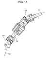
- Fig. 1 is a side view of the essential portion of the steering apparatus for a vehicle which incorporates therein the coupling structure according to an embodiment of the present invention.
- an intermediate shaft 103 is coupled to a lower end of a main shaft 101 which is coupled to a steering wheel (not shown) through an upper universal joint 102, while an input shaft 105 of a gear apparatus (not shown) is coupled to a lower end of the intermediate shaft 103 through a lower universal joint 104.
- Figs. 2A and 2B respectively illustrate different embodiments of the present invention, representing cross-sectional views of a steering shaft, a yoke of a universal joint, and an elastic shaft coupling interposed therebetween.
- the steering shaft 1 and the yoke 11 of the universal joint 11 are coupled to each other through an elastic universal joint.
- a stopper plate 3 having a cut-away portion 2 which is open outward in the radial direction and a disc-shaped elastic member 4 are secured to the steering shaft 1, while a flange 5 of the yoke 11 is attached to the shaft 1 through a bush 6.
- a pin 8 is inserted through the elastic member 4 and the flange 5 through a washer 7.
- An end of the pin 8 on the side of the yoke 11 is fixed by caulking.
- the washer 12 is attached to the flange 5 by welding, pressure contact, bolt fastening, bonding, or the like, and the end of the pin 8 on the side of the yoke 11 is fixed by caulking through this washer 12.
- the other end of the pin 8 is arranged to be brought into contact (engagement) with the cut-away portion of the stopper plate 3.
- the elastic member 4 transmits, while being elastically deformed, a steering torque by its deforming resistance.
- the other end of the pin 8 transmits, while being brought into contact (engagement) with the cut-away portion 2 of the stopper plate 3, a steering torque directly to the shaft 1 from the flange 5 of the yoke.
- the flange 5 has a pin insertion hole which is formed with a large diameter hole portion, a stepped receiving portion and a small diameter hole portion, while the pin 8 has a large diameter portion, a stepped portion and a small diameter portion which are respectively to be engaged with the large diameter hole portion, the stepped receiving portion and the small diameter hole portion of the pin insertion hole.
- the pin insertion hole portion 4a of the elastic member 4 is formed to be cylindrical, and the washer 7, though not shown in the drawing, may or may not be used.
- the flange 5 further has a pin insertion hole which is formed with a large diameter hole portion, a stepped receiving portion and a small diameter hole portion, while the pin 8 has a large diameter portion, a stepped portion and a small diameter portion which are respectively corresponding to the large diameter hole portion, the stepped receiving portion and the small diameter hole portion of the pin insertion hole.
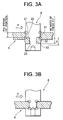
- Fig. 3A is a cross-sectional view of a coupling structure between a pin and a flange according to an embodiment of the present invention
- Fig. 3B is a cross-sectional view of a coupling structure between the pin and the flange according to the prior art.
- the flange 5 has a pin insertion hole which is formed with a large diameter hole portion 21, a stepped receiving portion 22 and a small diameter hole portion 23, while the pin 8 has a large diameter portion 31, a stepped portion 32 and a small diameter portion 33 which are respectively to be engaged with the large diameter hole portion 21, the stepped receiving portion 22 and the small diameter hole portion 23 of the pin insertion hole. Since the pin 8 and the pin insertion hole are respectively in stepped structures as described above so that the stress can be concentrated in the large diameter portion, it is possible to enhance the strength of the pin fixing structure.
- the stress concentrated portions enclosed with the circles are generated in the large diameter portion so that a stress value can be reduced and the strength of the pin can be enhanced.
- the thickness of the flange 5 can be reduced.
- the large diameter portion 31 of the pin 8 is press fitted in the large diameter hole portion 21 of the flange 5.
- the small diameter portion 33 of the pin 8 is press fitted in the small diameter hole portion 23 of the flange 5 in the above case, it is suffice if only inserting the small diameter portion 33 therein (with a clearance).
- F denotes a repeated load from the stopper plate 3.
- Fig. 3A it is possible to further suppress flexure of the pin with respect to F.
- the top of the hole for caulking and the flange 5 overlap each other so that the rigidity or the strength thereof is decreased.
- the top of the hole for caulking and the flange 5 do not overlap each other, it is possible to obtain high rigidity and strength.
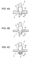
- Figs. 4A, 4B and 4C are respectively cross-sectional views of coupling structures between the pin and the flange according to different embodiments of the present invention.
- the flange 5 has a pin insertion hole which is formed with a large diameter hole portion 21, a stepped receiving portion 22 and a small diameter hole portion 23, while the pin 8 has a large diameter portion 31, a stepped portion 32 and a small diameter portion 33 which are respectively to be engaged with the large diameter hole portion 21, the stepped receiving portion 22 and the small diameter hole portion 23 of the pin insertion hole. Since the pin 8 and the pin insertion hole are respectively in stepped structures as described above so that the stress can be concentrated in the large diameter portion, it is possible to enhance the strength of the pin fixing structure.
- the outer side of the small diameter portion 23 of the flange 5 may be embossing-shaped, so that the thickness of the flange 5 can be reduced.
- an end of the pin 8 may be formed as a male thread shaft and may be thread engaged with and fixed by a nut 9.
- Figs. 5A and 5B are respectively cross-sectional views of coupling structures between the pin and the flange according to different embodiments of the present invention.
- the flange 5 has a pin insertion hole which is formed with a large diameter hole portion 21, a stepped receiving portion 22 and a small diameter hole portion 23, while the pin 8 comprises a large diameter portion 31, a stepped portion 32 and a small diameter portion 33 which are respectively to be engaged with the large diameter hole portion 21, the stepped receiving portion 22 and the small diameter hole portion 23 of the pin insertion hole. Since the pin 8 and the pin insertion hole are respectively in stepped structures as described above so that the stress can be concentrated in the large diameter portion, it is possible to enhance the strength of the pin fixing structure.
- the outer side of the small diameter portion 23 of the flange 5 is embossing-shaped, so that the thickness of the flange 5 can be reduced.
- the large diameter portion 31 of the pin 8 is press fitted in the large diameter hole portion 21 of the flange 5.
- the small diameter portion 33 of the pin 8 is press fitted in the small diameter hole portion of the flange 5, it is suffice if only inserting the small diameter portion 33 (with a clearance) therein.
- F denotes a repeated load from the stopper plate 3.
- Fig. 4A it is possible to further suppress the flexure of the pin with respect to F.
- an inclined hole portion 24 is formed between the stepped receiving portion 22 and the small diameter hole portion 23, and an inclined portion 34 corresponding to the inclined hole portion 24 is formed between the stepped portion 32 and the small diameter portion 33.
- Other arrangements in this embodiment are the same as those in the foregoing embodiments.
- Fig. 6A is a cross-sectional view of a pin and that of a flange according to an embodiment of the present invention
- Fig. 6B is a cross-sectional view of the pin and the flange shown in Fig. 6A, in a state that the pin and the flange are assembled.
- the large diameter portion 31 of the pin 8 is press fitted in the large diameter hole portion 21 of the flange 5.
- the small diameter portion 33 of the pin 8 is press fitted in the small diameter hole portion of the flange 5, it is suffice if only inserting the small diameter portion 33 therein(with a clearance).
- the length of the press fitted portion is preferably not less than 5% of the thickness of the flange plate, and most preferably not less than 30% thereof.
- An interference between the pin and the flange hole is not less than 0.005 mm, and most preferably in a range from 0.05 to 0.5 mm.
- the length of the portion A (the distance from the stepped receiving portion of the pin to the bottom of the caulking hole) in Figs. 6A and 6B is not less than 0.5 mm, and is preferably not less than 2 mm.
- a value which is recommended for caulking may be used as a value for the hardness of the thermal processing of the pin, which is preferably in a range from HV 100 to HV 400.
- the diameter of the press fitted portion of the pin is not less than ⁇ 4, and preferably in a range from ⁇ 8 to ⁇ 20.
- one of the steering torque transmitting members and the other of the steering torque transmitting members are adapted to transmit a steering torque through a pin
- one of the steering torque transmitting members has a pin insertion hole which is formed with a large diameter hole portion, a stepped receiving portion and a small diameter hole portion
- the pin has a large diameter portion, a stepped portion and a small diameter portion which are respectively to be engaged with the large diameter hole portion, the stepped receiving portion and the small diameter hole portion of the pin insertion hole.
- the pin and the pin insertion hole respectively have stepped structures, so as to concentrate the stress on the large diameter portion.
Landscapes
- Engineering & Computer Science (AREA)
- General Engineering & Computer Science (AREA)
- Mechanical Engineering (AREA)
- Chemical & Material Sciences (AREA)
- Combustion & Propulsion (AREA)
- Transportation (AREA)
- Steering Controls (AREA)
Abstract
Description
Claims (3)
- A coupling structure of steering torque transmitting members for a steering shaft for coupling a pair of steering torque transmitting members interposed in a steering shaft, characterized in that:one of the steering torque transmitting members and the other of the steering torque transmitting members are adapted to transmit a steering torque through a pin;said one of the steering torque transmitting members has a pin insertion hole formed with a large diameter hole portion, a stepped receiving portion and a small diameter hole portion; andsaid pin has a large diameter portion, a stepped portion and a small diameter portion which are respectively engaged with the large diameter hole portion, the stepped receiving portion and the small diameter hole portion of the pin insertion hole.
- A coupling structure of steering torque transmitting members for a steering shaft according to Claim 1, wherein said large diameter portion of the pin is press fitted in the large diameter hole portion of the pin insertion hole.
- A coupling structure of steering torque transmitting members for a steering shaft according to Claim 1 or 2, wherein said pin projected from said pin insertion hole is fixed to said one of the steering torque transmitting members by caulking or thread engaging means.
Applications Claiming Priority (3)
| Application Number | Priority Date | Filing Date | Title |
|---|---|---|---|
| JP2002249384 | 2002-08-28 | ||
| JP2002249384 | 2002-08-28 | ||
| PCT/JP2003/010917 WO2004020860A1 (en) | 2002-08-28 | 2003-08-28 | Connection structure of steering torque transmission member for steering shaft |
Publications (2)
| Publication Number | Publication Date |
|---|---|
| EP1553317A1 true EP1553317A1 (en) | 2005-07-13 |
| EP1553317A4 EP1553317A4 (en) | 2006-05-10 |
Family
ID=31972572
Family Applications (1)
| Application Number | Title | Priority Date | Filing Date |
|---|---|---|---|
| EP03791365A Withdrawn EP1553317A4 (en) | 2002-08-28 | 2003-08-28 | Connection structure of steering torque transmission member for steering shaft |
Country Status (6)
| Country | Link |
|---|---|
| US (1) | US7393282B2 (en) |
| EP (1) | EP1553317A4 (en) |
| JP (1) | JPWO2004020860A1 (en) |
| CN (1) | CN1324247C (en) |
| AU (1) | AU2003257570A1 (en) |
| WO (1) | WO2004020860A1 (en) |
Families Citing this family (1)
| Publication number | Priority date | Publication date | Assignee | Title |
|---|---|---|---|---|
| CN102673633A (en) * | 2012-05-16 | 2012-09-19 | 无锡金也汽车部件有限公司 | Steering under-drive shaft assembly |
Family Cites Families (16)
| Publication number | Priority date | Publication date | Assignee | Title |
|---|---|---|---|---|
| US2067284A (en) * | 1934-11-15 | 1937-01-12 | John W B Pearce | Flexible joint |
| US2564905A (en) * | 1946-10-28 | 1951-08-21 | John W Kaye | Shock absorbing wheel |
| US2982118A (en) * | 1959-07-18 | 1961-05-02 | Gomma Antivibranti Applic | Resilient transmission joints for shafts |
| US3684999A (en) * | 1970-11-09 | 1972-08-15 | Gen Motors Corp | Conductive flexible coupling |
| JPS6035938A (en) * | 1983-08-03 | 1985-02-23 | Sanyo Electric Co Ltd | Stator securing method of compressor |
| JPS60201119A (en) * | 1984-03-26 | 1985-10-11 | Fuji Kiko Co Ltd | Elastic joint device of shaft |
| JPH034031A (en) | 1989-05-30 | 1991-01-10 | Nippon Seiko Kk | Elastic joint for steering shaft |
| US5222913A (en) * | 1989-05-30 | 1993-06-29 | Nippon Seiko Kabushiki Kaisha | Resilient connector for steering shaft |
| KR920014678A (en) * | 1991-01-29 | 1992-08-25 | 에타블리서멘트 쥬퍼비스 | Steering shaft of vehicle |
| JPH0885403A (en) * | 1994-09-16 | 1996-04-02 | Suzuki Motor Corp | Bumper mounting structure |
| US5632684A (en) * | 1995-10-24 | 1997-05-27 | Xerox Corporation | Stepped shaft assembly |
| JP3247605B2 (en) | 1996-04-11 | 2002-01-21 | 株式会社山田製作所 | Elastic shaft coupling device |
| JP3692733B2 (en) * | 1997-10-09 | 2005-09-07 | 日本精工株式会社 | Steering joint device for automobile |
| JP3482343B2 (en) * | 1998-08-20 | 2003-12-22 | 富士機工株式会社 | Damper for steering column |
| JP2001280355A (en) * | 2000-03-31 | 2001-10-10 | Nsk Ltd | Elastic shaft coupling |
| JP3850209B2 (en) * | 2000-06-07 | 2006-11-29 | 株式会社日立製作所 | Power transmission shaft for vehicles |
-
2003
- 2003-08-28 AU AU2003257570A patent/AU2003257570A1/en not_active Abandoned
- 2003-08-28 JP JP2004532749A patent/JPWO2004020860A1/en active Pending
- 2003-08-28 EP EP03791365A patent/EP1553317A4/en not_active Withdrawn
- 2003-08-28 US US10/525,946 patent/US7393282B2/en not_active Expired - Lifetime
- 2003-08-28 CN CNB038205793A patent/CN1324247C/en not_active Expired - Fee Related
- 2003-08-28 WO PCT/JP2003/010917 patent/WO2004020860A1/en not_active Ceased
Also Published As
| Publication number | Publication date |
|---|---|
| WO2004020860A1 (en) | 2004-03-11 |
| EP1553317A4 (en) | 2006-05-10 |
| CN1678840A (en) | 2005-10-05 |
| CN1324247C (en) | 2007-07-04 |
| US20050239559A1 (en) | 2005-10-27 |
| US7393282B2 (en) | 2008-07-01 |
| JPWO2004020860A1 (en) | 2005-12-15 |
| AU2003257570A1 (en) | 2004-03-19 |
Similar Documents
| Publication | Publication Date | Title |
|---|---|---|
| JP3264616B2 (en) | Elastic joints in steering devices | |
| EP0392858A1 (en) | Stroke absorbing type intermediate shaft for vehicular steering column and method for assembling the same | |
| JP3646556B2 (en) | Elastic shaft coupling | |
| US6022047A (en) | Universal joint and a yoke therefor for a steering apparatus | |
| US10981441B2 (en) | Torque rod | |
| US5916026A (en) | Elastic universal joint | |
| US5188474A (en) | Yoke for universal joint | |
| EP1852631A1 (en) | Vibration isolating device | |
| US8303423B2 (en) | Power transmission | |
| JP3850209B2 (en) | Power transmission shaft for vehicles | |
| US5984790A (en) | Universal joint | |
| US7393282B2 (en) | Coupling structure of steering torque transmitting member for steering shaft | |
| US10780768B2 (en) | Torque rod | |
| WO2005078302A1 (en) | Constant velocity universal joint | |
| JP2000103338A (en) | Connection structure of rotating shaft | |
| US20080164114A1 (en) | Vibration Isolating Device | |
| JP3883380B2 (en) | Vehicle shaft coupling | |
| EP0532834A2 (en) | Flexible coupling with centering device | |
| JP2002114155A (en) | Steering device | |
| JP2001027256A (en) | Elastic shaft coupling | |
| JP2544823Y2 (en) | Anti-vibration propeller shaft | |
| GB2322687A (en) | Elastic universal joint assembly | |
| JP4070567B2 (en) | Elastic universal joint | |
| JP4165211B2 (en) | Universal joint yoke | |
| JPH08200382A (en) | Elastic universal joint |
Legal Events
| Date | Code | Title | Description |
|---|---|---|---|
| PUAI | Public reference made under article 153(3) epc to a published international application that has entered the european phase |
Free format text: ORIGINAL CODE: 0009012 |
|
| 17P | Request for examination filed |
Effective date: 20050323 |
|
| AK | Designated contracting states |
Kind code of ref document: A1 Designated state(s): AT BE BG CH CY CZ DE DK EE ES FI FR GB GR HU IE IT LI LU MC NL PT RO SE SI SK TR |
|
| AX | Request for extension of the european patent |
Extension state: AL LT LV MK |
|
| DAX | Request for extension of the european patent (deleted) | ||
| RBV | Designated contracting states (corrected) |
Designated state(s): DE FR GB |
|
| A4 | Supplementary search report drawn up and despatched |
Effective date: 20060327 |
|
| RIC1 | Information provided on ipc code assigned before grant |
Ipc: B62D 1/16 20060101ALI20060321BHEP Ipc: F16D 3/70 20060101ALI20060321BHEP Ipc: F16D 3/78 20060101AFI20040317BHEP |
|
| 17Q | First examination report despatched |
Effective date: 20080523 |
|
| 18D | Application deemed to be withdrawn |
Effective date: 20110302 |
|
| STAA | Information on the status of an ep patent application or granted ep patent |
Free format text: STATUS: THE APPLICATION IS DEEMED TO BE WITHDRAWN |
|
| R18D | Application deemed to be withdrawn (corrected) |
Effective date: 20110301 |