EP1553301A1 - Vane type vacuum pump - Google Patents
Vane type vacuum pump Download PDFInfo
- Publication number
- EP1553301A1 EP1553301A1 EP02808018A EP02808018A EP1553301A1 EP 1553301 A1 EP1553301 A1 EP 1553301A1 EP 02808018 A EP02808018 A EP 02808018A EP 02808018 A EP02808018 A EP 02808018A EP 1553301 A1 EP1553301 A1 EP 1553301A1
- Authority
- EP
- European Patent Office
- Prior art keywords
- rotor
- vane
- housing
- vacuum pump
- type vacuum
- Prior art date
- Legal status (The legal status is an assumption and is not a legal conclusion. Google has not performed a legal analysis and makes no representation as to the accuracy of the status listed.)
- Granted
Links
Images




Classifications
-
- F—MECHANICAL ENGINEERING; LIGHTING; HEATING; WEAPONS; BLASTING
- F01—MACHINES OR ENGINES IN GENERAL; ENGINE PLANTS IN GENERAL; STEAM ENGINES
- F01C—ROTARY-PISTON OR OSCILLATING-PISTON MACHINES OR ENGINES
- F01C21/00—Component parts, details or accessories not provided for in groups F01C1/00 - F01C20/00
- F01C21/10—Outer members for co-operation with rotary pistons; Casings
- F01C21/104—Stators; Members defining the outer boundaries of the working chamber
-
- F—MECHANICAL ENGINEERING; LIGHTING; HEATING; WEAPONS; BLASTING
- F04—POSITIVE - DISPLACEMENT MACHINES FOR LIQUIDS; PUMPS FOR LIQUIDS OR ELASTIC FLUIDS
- F04C—ROTARY-PISTON, OR OSCILLATING-PISTON, POSITIVE-DISPLACEMENT MACHINES FOR LIQUIDS; ROTARY-PISTON, OR OSCILLATING-PISTON, POSITIVE-DISPLACEMENT PUMPS
- F04C18/00—Rotary-piston pumps specially adapted for elastic fluids
- F04C18/30—Rotary-piston pumps specially adapted for elastic fluids having the characteristics covered by two or more of groups F04C18/02, F04C18/08, F04C18/22, F04C18/24, F04C18/48, or having the characteristics covered by one of these groups together with some other type of movement between co-operating members
- F04C18/34—Rotary-piston pumps specially adapted for elastic fluids having the characteristics covered by two or more of groups F04C18/02, F04C18/08, F04C18/22, F04C18/24, F04C18/48, or having the characteristics covered by one of these groups together with some other type of movement between co-operating members having the movement defined in group F04C18/08 or F04C18/22 and relative reciprocation between the co-operating members
- F04C18/344—Rotary-piston pumps specially adapted for elastic fluids having the characteristics covered by two or more of groups F04C18/02, F04C18/08, F04C18/22, F04C18/24, F04C18/48, or having the characteristics covered by one of these groups together with some other type of movement between co-operating members having the movement defined in group F04C18/08 or F04C18/22 and relative reciprocation between the co-operating members with vanes reciprocating with respect to the inner member
-
- F—MECHANICAL ENGINEERING; LIGHTING; HEATING; WEAPONS; BLASTING
- F01—MACHINES OR ENGINES IN GENERAL; ENGINE PLANTS IN GENERAL; STEAM ENGINES
- F01C—ROTARY-PISTON OR OSCILLATING-PISTON MACHINES OR ENGINES
- F01C21/00—Component parts, details or accessories not provided for in groups F01C1/00 - F01C20/00
- F01C21/08—Rotary pistons
- F01C21/0809—Construction of vanes or vane holders
-
- F—MECHANICAL ENGINEERING; LIGHTING; HEATING; WEAPONS; BLASTING
- F04—POSITIVE - DISPLACEMENT MACHINES FOR LIQUIDS; PUMPS FOR LIQUIDS OR ELASTIC FLUIDS
- F04C—ROTARY-PISTON, OR OSCILLATING-PISTON, POSITIVE-DISPLACEMENT MACHINES FOR LIQUIDS; ROTARY-PISTON, OR OSCILLATING-PISTON, POSITIVE-DISPLACEMENT PUMPS
- F04C18/00—Rotary-piston pumps specially adapted for elastic fluids
- F04C18/30—Rotary-piston pumps specially adapted for elastic fluids having the characteristics covered by two or more of groups F04C18/02, F04C18/08, F04C18/22, F04C18/24, F04C18/48, or having the characteristics covered by one of these groups together with some other type of movement between co-operating members
- F04C18/34—Rotary-piston pumps specially adapted for elastic fluids having the characteristics covered by two or more of groups F04C18/02, F04C18/08, F04C18/22, F04C18/24, F04C18/48, or having the characteristics covered by one of these groups together with some other type of movement between co-operating members having the movement defined in group F04C18/08 or F04C18/22 and relative reciprocation between the co-operating members
- F04C18/344—Rotary-piston pumps specially adapted for elastic fluids having the characteristics covered by two or more of groups F04C18/02, F04C18/08, F04C18/22, F04C18/24, F04C18/48, or having the characteristics covered by one of these groups together with some other type of movement between co-operating members having the movement defined in group F04C18/08 or F04C18/22 and relative reciprocation between the co-operating members with vanes reciprocating with respect to the inner member
- F04C18/3441—Rotary-piston pumps specially adapted for elastic fluids having the characteristics covered by two or more of groups F04C18/02, F04C18/08, F04C18/22, F04C18/24, F04C18/48, or having the characteristics covered by one of these groups together with some other type of movement between co-operating members having the movement defined in group F04C18/08 or F04C18/22 and relative reciprocation between the co-operating members with vanes reciprocating with respect to the inner member the inner and outer member being in contact along one line or continuous surface substantially parallel to the axis of rotation
- F04C18/3442—Rotary-piston pumps specially adapted for elastic fluids having the characteristics covered by two or more of groups F04C18/02, F04C18/08, F04C18/22, F04C18/24, F04C18/48, or having the characteristics covered by one of these groups together with some other type of movement between co-operating members having the movement defined in group F04C18/08 or F04C18/22 and relative reciprocation between the co-operating members with vanes reciprocating with respect to the inner member the inner and outer member being in contact along one line or continuous surface substantially parallel to the axis of rotation the surfaces of the inner and outer member, forming the inlet and outlet opening
-
- F—MECHANICAL ENGINEERING; LIGHTING; HEATING; WEAPONS; BLASTING
- F04—POSITIVE - DISPLACEMENT MACHINES FOR LIQUIDS; PUMPS FOR LIQUIDS OR ELASTIC FLUIDS
- F04C—ROTARY-PISTON, OR OSCILLATING-PISTON, POSITIVE-DISPLACEMENT MACHINES FOR LIQUIDS; ROTARY-PISTON, OR OSCILLATING-PISTON, POSITIVE-DISPLACEMENT PUMPS
- F04C25/00—Adaptations of pumps for special use of pumps for elastic fluids
- F04C25/02—Adaptations of pumps for special use of pumps for elastic fluids for producing high vacuum
-
- F—MECHANICAL ENGINEERING; LIGHTING; HEATING; WEAPONS; BLASTING
- F04—POSITIVE - DISPLACEMENT MACHINES FOR LIQUIDS; PUMPS FOR LIQUIDS OR ELASTIC FLUIDS
- F04C—ROTARY-PISTON, OR OSCILLATING-PISTON, POSITIVE-DISPLACEMENT MACHINES FOR LIQUIDS; ROTARY-PISTON, OR OSCILLATING-PISTON, POSITIVE-DISPLACEMENT PUMPS
- F04C27/00—Sealing arrangements in rotary-piston pumps specially adapted for elastic fluids
- F04C27/005—Axial sealings for working fluid
-
- F—MECHANICAL ENGINEERING; LIGHTING; HEATING; WEAPONS; BLASTING
- F04—POSITIVE - DISPLACEMENT MACHINES FOR LIQUIDS; PUMPS FOR LIQUIDS OR ELASTIC FLUIDS
- F04C—ROTARY-PISTON, OR OSCILLATING-PISTON, POSITIVE-DISPLACEMENT MACHINES FOR LIQUIDS; ROTARY-PISTON, OR OSCILLATING-PISTON, POSITIVE-DISPLACEMENT PUMPS
- F04C2220/00—Application
- F04C2220/10—Vacuum
Definitions
- This invention relates to a vane-type vacuum pump and, more particularly, to a vane-type vacuum pump for evacuating a tank for use in vehicles.
- the conventional vane-type vacuum pump shown in section in Figs. 12 and 13 comprises a housing 1, which comprises a cup-shaped main body 3 including a suction port 2 and a discharge port 4 with a valve and a bracket 6 closing an open end of the main body 3 for defining a pump chamber 5 therein.
- the pump chamber 5 is a cylindrical space defined in the housing 1 by two parallel end faces 7 and 8, and a cylindrical surface 9 between the end faces 7 and 8.
- a bearing 10 of the bracket 6 supports a rotary shaft 11 in an eccentric relationship with respect to a central axis of the cylindrical pump chamber 5, and an inner end of the rotary shaft 11 is supported by a bearing 12 of the main body 13.
- Secured to an outer end of the rotary shaft 11 are a pinion, a pulley, a sprocket, cum and the like 13 for receiving a driving power from an external drive unit (not illustrated) such as gears.
- a rotor 14 is housed in a concentric relationship with the rotary shaft 11 and therefore in an eccentric relationship with the pump chamber 5 (housing 1).
- the rotor 14 is a substantially cylindrical member having two end surfaces and a cylindrical surface and is rotated by the rotary shaft 11 within the housing 1.
- the rotor 14 is provided with four slots 15 radially extending from one end surface to the other, the slots 15 each has inserted therein a vane 16 radially slidable and capable of being brought into a slidable contact at its tip with a cylindrical surface 9 of the housing 1
- engine oil is supplied to various sliding contact portions of the vane-type vacuum pump such as those portions of the vanes 16 that is sliding-contacting with other portions such as the rotor 14, the end surfaces 7 and 8 and the cylindrical surface 9 and also to the bearing portions and those sliding contact portions are lubricated.
- the portions between the side end surfaces 7 and 8 of the housing 1 and the axial end surfaces of the rotor 14 are also sliding portions, in which engine oil films are interposed to prevent abrasion between these portions and to establish hermetic seal between the rotor and the housing.
- the oil films in these sliding portions can be locally broken. Once the oil films are broken, not only the problem of friction arises, but also the effect of hermetic seal is reduced, causing the problem of degrading the vacuum characteristics of the vane-type vacuum pump.
- the former measure increases the overall dimensions of the vane-type vacuum pump and poses the problems such as poor mountability of the engine and increase the weight and the latter measure poses the problems such as shortened life due to increased vibration, increased mechanical wear and the like.
- the object of the present invention is to provide a vane-type vacuum pump of small size that is improved in hermetic seal between the rotor and the housing to exhibits good vacuum characteristics, a sufficient lubrication can be maintained to reduce wear.
- the vane-type vacuum pump of the present invention has the construction as described bellow.
- a vane-type vacuum pump of the present invention illustrated in Figs. 1 to 3 comprises a housing 21, which comprises a cup-shaped main body 23 having a suction port 22 and a discharge port 24 both with a valve, and a bracket 26 closing an open end of the main body 23 to define a pump chamber 25 therein.
- the pump chamber 25 is a space defined by two parallel end surfaces 27 and 28 of the housing 21 and a cylindrical surface 29 between the end surfaces 27 and 28.
- a bearing 30 of the bracket 26 supports a rotary shaft 31 disposed extending through the cylindrical pump chamber 25 and the inner end of the rotary shaft 31 is supported in an eccentric relationship relative to a central axis of the pump chamber 25.
- An outer end of the rotary shaft 31 has secured thereto a pinion 33, pulley, sprocket, cum or the like for receiving a driving force from an external drive unit (not illustrated) such as gears or the like.
- a rotor 34 concentric to the rotary shaft 31 and therefore eccentric to the pump chamber 25 (the housing 21) is accommodated.
- the rotor 34 is a substantially cylindrical member having two flat end surfaces 35 and 36 and a cylindrical surface 37 and the rotor 34 is caused to rotated by the rotary shaft 31 within the housing 21.
- the rotor 34 is provided with four slots 38 extending through the rotor 34 in the radial direction from one end surface to the other.
- These slots 38 each has inserted therein a plate shaped vane 42 that can be brought into sliding contact at its tip end 39 with the cylindrical surface 29 of the housing 21 and that is in sliding contact at flat end surfaces 40 and 41 with the end surfaces 27 and 28 of the housing 21, the vanes 42 being slidable in the slots 38 in the radial direction.
- the rotor 34 has provided on the end surfaces 35 and 36, except at the position where the slot 38 is formed, with an annular ridge or projection ring 43 concentric with the rototary shaft 31.
- a continuous annular groove 44 is provided at the position corresponding to the annular projection ring 43 for receiving therein the projection ring 43.
- the clearance 45 in the radial direction as well as the clearance 46 in the radial direction between the groove 44 and the projection ring 43 are made greater than the clearances between the end surfaces 35, 36 of the rotor 34 and the end surfaces 27, 28 of the housing 21, .and the axial clearance 46 is made greater than the radial clearance 45.
- a space for maintaining engine oil is defined between the annular projection ring 43 and the annular groove 44. Since this space is defined between the projection ring 43 and the groove 44, it is a labyrinth seal for preventing the engine oil from flowing in the radial direction.
- the sliding contact portion between the side end surfaces 27 and 28 of the housing 1 and the axial end surfaces 35 and 36 of the rotor 34 are provided with the annular projection ring 43 concentric to the rotary shaft 31 and the annular continuous groove 44 for receiving the projection ring 43 therein, whereby a U-shaped bent labyrinth-like seal is defined therebetween and at the same time a space in which engine oil can be maintained is defined. Therefore, this labyrinth-like seal can prevent the engine oil from flowing out through the sliding portion and the oil film from being broken, and the oil reservoir space can continue to supply engine oil, so that the wearing of the sliding contact portion can be prevented and the hermetic seal between the rotor and the housing can be maintained.
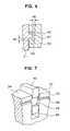
- Figs. 5 to 7 illustrate an example in which an annular projection ring 47 is disposed on the side walls 27 and 28 of the housing 21 and an annular groove 48 is disposed in the end surfaces 35 and 36 of the rotor 34.
- the projection ring 47 on the housing 21 is a continuous annular ridge-shaped projection having a substantially rectangular cross-section and concentric to the rotary shaft 31 of the rotor 34.
- the groove 48 in the rotor 34 is an annular groove concentric to the rotary shaft 31 for receiving the projection ring 47 therein, but is discontinuous at the position where the slots 38 for accommodating the vanes 42 are located.
- recesses 49 as escape grooves are provided for allowing the vanes 42 to be slidably movable within the slots 38 in the radial direction relative to the rotor 34 without interfering with the projection ring 47 on the housing 21.
- the sliding contact portion between the side end surfaces 27 and 28 of the housing 1 and the axial end surfaces 35 and 36 of the rotor 34 are provided with the annular projection ring 47 on the housing 21 and the annular continuous groove 48 for receiving the projection ring 47 therein at the side of the rotor 34, whereby a U-shaped bent labyrinth-like seal is defined between the groove 48 and the projection ring 47, and at the same time a space in which engine oil can be maintained is defined. Therefore, the wearing of the sliding contact portion can be prevented and the hermetic seal between the rotor and the housing can be maintained.
- rotor 34 is provided at the end surfaces with two annular projection rings 51 and 52 and the housing 21 is provided with two annular grooves 53 and 54.
- Each of the projection rings 51 and 52 and the grooves 53 and 54 has similar structure to those shown in Figs. 1 to 4.
- labyrinth-like seal and the oil reservoir space are doubled, so that the sealing function is significantly improved as compared to that of the previous embodiments.
- rotor 34 is provided at the end surfaces with two annular grooves 55 and 56 and the housing 21 is provided with two annular projection rings 57 and 58.
- Each of the grooves 55 and 56 and the projection rings 57 and 58 has similar structure to those shown in Figs. 5 to 7.
- Escape grooves 59 provided in the end surfaces 47 and 48 of the vanes 42 have a radial dimension large enough to prevent interference with the doubled projection rings 55 and 56 and the doubled grooves 57 and 58.
- labyrinth-like seal and the oil reservoir space are doubled, so that the sealing function is significantly improved as compared to that of the previous embodiments.
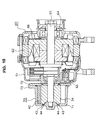
- Fig. 10 is a schematic sectional view showing an example in which the vane-type vacuum pump shown in Figs. 1 to 4 is directly connected to a vehicular ac generator.
- the vehicular ac generator 60 comprises a stator 62 supported within a housing 61 and a rotor 66 having a rotary shaft 65 supported by bearings 63 and 64 mounted to the housing 61, the rotary shaft 65 extends at its left-hand end as viewed in the figure to the outside of the housing 61 and into the housing 71 of the vane-type vacuum pump 70 of the present invention.
- the bracket 72 of the housing 71 of the vane-type vacuum pump 70 is attached to the housing 61 of the vehicular ac generator 60, and, while the bracket 72 has no bearing, the bracket 72 has attached thereto a housing main body 73 to constitute the housing 71 of the pump.
- Attached to the rotary shaft 65 within the housing 71 is the rotor 34 of the vane-type vacuum pump 70 and the annular projection rings 43 and the annular grooves 44 of the present invention are disposed between the rotor 34 and the housing 71, whereby a labyrinth-like seal extending in substantially entire circumference is provided.
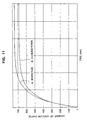
- Fig. 11 is a graph showing the comparison test results as to the vacuum degree of the vane-type vacuum pump shown in Figs. 1 to 4 and the conventional vane-type vacuum pump shown in Figs. 12 and 13.
- Two curves A and B show the degrees of vacuum expressed in the height (mmHg) of a mercury column at the suction side of the vane-type vacuum pump as plotted against the operation time (seconds) on abscissa, the curve A representing the vacuum characteristics of the vane-type vacuum pump of the present invention and the curve B representing the vacuum characteristics of the conventional vane-type vacuum pump.
- the vane-type vacuum pump of the present invention comprises a labyrinth seal extending over an entire circumference, the labyrinth seal including at least one pair of circular ring-shaped grooves 44 and 48 and circular ridge-shaped projection rings 43 and 44 disposed concentrically to the rotary shaft 31 between the housing 21 and the rotor 34, the grooves and the projection rings engaging together and being relatively movable to each other in circumferential direction.
- the circular projection rings 43 may be disposed on the end surfaces of the rotor 34 and the circular ring-shaped grooves 44 may be disposed in the housing 21, the circular ring-shaped grooves 48 may be disposed in side end surfaces of the rotor 34 and the circular ridge-shaped projection rings 47 may be disposed on the housing 21, and wherein grooves 49 may be provided in the side end surfaces of the vane 42 for receiving the projection rings 476 not to impede the radial movement of the vane 42.
- the labyrinth seal may be concentrically provided in a plurality of pairs, or the labyrinth seal may be disposed on both side end surfaces of the rotor.
- the vane-type vacuum pump of the present invention is useful as a vacuum pump for evacuating a tank constituting a vehicular brake assistor, for example.
Landscapes
- Engineering & Computer Science (AREA)
- Mechanical Engineering (AREA)
- General Engineering & Computer Science (AREA)
- Rotary Pumps (AREA)
- Applications Or Details Of Rotary Compressors (AREA)
Abstract
Description
Claims (6)
- A vane-type vacuum pump comprising;wherein the air within said pump chamber is pumped from said suction port to said discharge port by the rotation of said rotor to generate a vacuum on the side of said suction port side; characterized by a labyrinth seal disposed between said housing and said rotor to extending over an entire circumference and including at least one pair of a circular ring-shaped groove and a circular ridge-shaped projection ring concentrically disposed to said rotary shaft, said groove and said projection ring engage together and relatively movable to each other in circumferential direction.a housing having a cylindrical pump chamber including a suction port and a discharge port;a rotor eccentrically accommodated within said pump chamber;a rotary shaft secured to said rotor for rotating said rotor within said pump chamber; anda vane radially movably inserted into said rotor while maintaining a sliding contact with said housing within said pump chamber;
- A vane-type vacuum pump as claimed in claim 1, wherein said circular ridge-shaped projection ring is disposed on the end surface of said rotor and said circular ring-shaped groove is disposed in said housing.
- A vane-type vacuum pump as claimed in claim 1, wherein said circular ring-shaped groove is disposed in a side end surface of said rotor and said circular ridge-shaped projection ring is disposed on the housing, and
wherein a groove is provided in the side end surface of said vane for receiving said projection ring not to impede the radial movement of said vane. - A vane-type vacuum pump as claimed in any one of claims 1 to 3,
wherein said labyrinth seal is concentrically provided in a plurality of pairs. - A vane-type vacuum pump as claimed in any one of claims 1 to 3,
wherein said labyrinth seal is disposed on both side end faces of said rotor. - A vane-type vacuum pump as claimed in any one of claims 1 to 3,
wherein said said rotary shaft is an output rotary shaft of a vehicular alternator.
Applications Claiming Priority (1)
| Application Number | Priority Date | Filing Date | Title |
|---|---|---|---|
| PCT/JP2002/010661 WO2004036046A1 (en) | 2002-10-15 | 2002-10-15 | Vane type vacuum pump |
Publications (3)
| Publication Number | Publication Date |
|---|---|
| EP1553301A1 true EP1553301A1 (en) | 2005-07-13 |
| EP1553301A4 EP1553301A4 (en) | 2006-10-11 |
| EP1553301B1 EP1553301B1 (en) | 2008-09-03 |
Family
ID=32104819
Family Applications (1)
| Application Number | Title | Priority Date | Filing Date |
|---|---|---|---|
| EP02808018A Expired - Lifetime EP1553301B1 (en) | 2002-10-15 | 2002-10-15 | Vane type vacuum pump |
Country Status (6)
| Country | Link |
|---|---|
| EP (1) | EP1553301B1 (en) |
| JP (1) | JP4014109B2 (en) |
| KR (1) | KR100607321B1 (en) |
| CN (1) | CN100370141C (en) |
| DE (1) | DE60228765D1 (en) |
| WO (1) | WO2004036046A1 (en) |
Cited By (4)
| Publication number | Priority date | Publication date | Assignee | Title |
|---|---|---|---|---|
| EP1925778A1 (en) * | 2006-11-24 | 2008-05-28 | Matsushita Electric Works, Ltd. | Vane pump |
| WO2009090079A3 (en) * | 2008-01-16 | 2009-11-12 | Vhit S.P.A. - Unipersonale | A displacement pump with a barrier against the fluid leakage |
| DE102018105144A1 (en) * | 2018-03-06 | 2019-09-12 | Schwäbische Hüttenwerke Automotive GmbH | Axial sealing element Vacuum pump |
| US11035363B2 (en) | 2016-03-24 | 2021-06-15 | Taiho Kogyo Co., Ltd. | Vane pump |
Families Citing this family (10)
| Publication number | Priority date | Publication date | Assignee | Title |
|---|---|---|---|---|
| JP3849799B2 (en) * | 2005-02-16 | 2006-11-22 | 大豊工業株式会社 | Vane pump |
| JP4811243B2 (en) * | 2006-11-24 | 2011-11-09 | パナソニック電工株式会社 | Vane pump |
| JP4976827B2 (en) * | 2006-11-24 | 2012-07-18 | パナソニック株式会社 | Vane pump |
| CN102878080A (en) * | 2012-10-30 | 2013-01-16 | 东风汽车公司 | Electric vacuum pump |
| CN103306979B (en) * | 2013-06-28 | 2015-12-30 | 常州市东南电器电机股份有限公司 | Electronic vacuum pump for new energy vehicle brake vacuum booster |
| CN105317681B (en) * | 2014-07-07 | 2017-11-14 | 珠海格力节能环保制冷技术研究中心有限公司 | Helical-lobe compressor |
| EP2987951B1 (en) * | 2014-08-22 | 2017-02-15 | WABCO Europe BVBA | Vacuum pump with eccentrically driven vane |
| CN110374873A (en) * | 2019-08-20 | 2019-10-25 | 泓道(上海)科技有限公司 | Sliding-vane air compressor |
| KR102301479B1 (en) * | 2020-03-27 | 2021-09-13 | 엘지전자 주식회사 | Rotary compressor |
| CN119641627B (en) * | 2024-09-30 | 2025-09-05 | 赵标科技(北京)有限公司 | Rotating mechanism, sealing mechanism and sealing method thereof |
Family Cites Families (10)
| Publication number | Priority date | Publication date | Assignee | Title |
|---|---|---|---|---|
| GB455994A (en) * | 1935-05-02 | 1936-11-02 | David Hamilton Cockburn | Improvements in or relating to pumps and fluid-pressure motors of the rotating vane type |
| JPS53114510A (en) * | 1977-03-17 | 1978-10-06 | Nippon Carbureter | Vacuum pump directly coupled to alternator |
| JP2947030B2 (en) * | 1993-11-10 | 1999-09-13 | 松下電器産業株式会社 | Vane rotary compressor |
| JPH07279678A (en) * | 1994-04-15 | 1995-10-27 | Tochigi Fuji Ind Co Ltd | Screw type supercharger |
| JPH07317674A (en) * | 1994-05-27 | 1995-12-05 | Shuichi Kitamura | Unlubricated vane pump |
| JPH0874767A (en) * | 1994-09-07 | 1996-03-19 | Shuichi Kitamura | Oilless type rotary pump having vane |
| CN2239513Y (en) * | 1996-04-02 | 1996-11-06 | 花少华 | Wet vacuum pump |
| AUPO086196A0 (en) * | 1996-07-08 | 1996-08-01 | Boyle, Bede Alfred | Rotary engine |
| SE0003075D0 (en) * | 2000-08-31 | 2000-08-31 | Delaval Holding Ab | Vacuum pump |
| JP2002161881A (en) * | 2000-11-30 | 2002-06-07 | Denso Corp | Vacuum pump |
-
2002
- 2002-10-15 WO PCT/JP2002/010661 patent/WO2004036046A1/en not_active Ceased
- 2002-10-15 DE DE60228765T patent/DE60228765D1/en not_active Expired - Lifetime
- 2002-10-15 EP EP02808018A patent/EP1553301B1/en not_active Expired - Lifetime
- 2002-10-15 KR KR1020047013322A patent/KR100607321B1/en not_active Expired - Fee Related
- 2002-10-15 CN CNB028283503A patent/CN100370141C/en not_active Expired - Fee Related
- 2002-10-15 JP JP2004525636A patent/JP4014109B2/en not_active Expired - Fee Related
Cited By (5)
| Publication number | Priority date | Publication date | Assignee | Title |
|---|---|---|---|---|
| EP1925778A1 (en) * | 2006-11-24 | 2008-05-28 | Matsushita Electric Works, Ltd. | Vane pump |
| US7628594B2 (en) | 2006-11-24 | 2009-12-08 | Matsushita Electric Works, Ltd. | Vane pump having a labyrinth seal and gap between a top surface of a rotor and a ceiling surface of a rotor chamber that is formed between upper and lower cases |
| WO2009090079A3 (en) * | 2008-01-16 | 2009-11-12 | Vhit S.P.A. - Unipersonale | A displacement pump with a barrier against the fluid leakage |
| US11035363B2 (en) | 2016-03-24 | 2021-06-15 | Taiho Kogyo Co., Ltd. | Vane pump |
| DE102018105144A1 (en) * | 2018-03-06 | 2019-09-12 | Schwäbische Hüttenwerke Automotive GmbH | Axial sealing element Vacuum pump |
Also Published As
| Publication number | Publication date |
|---|---|
| DE60228765D1 (en) | 2008-10-16 |
| EP1553301A4 (en) | 2006-10-11 |
| KR20040094737A (en) | 2004-11-10 |
| JPWO2004036046A1 (en) | 2006-02-16 |
| JP4014109B2 (en) | 2007-11-28 |
| KR100607321B1 (en) | 2006-07-31 |
| CN100370141C (en) | 2008-02-20 |
| CN1623038A (en) | 2005-06-01 |
| EP1553301B1 (en) | 2008-09-03 |
| WO2004036046A1 (en) | 2004-04-29 |
Similar Documents
| Publication | Publication Date | Title |
|---|---|---|
| EP1553301B1 (en) | Vane type vacuum pump | |
| US6439867B1 (en) | Scroll compressor having a clearance for the oldham coupling | |
| KR20010078226A (en) | Scroll compressor | |
| CN102312834A (en) | Convolute-hydrodynamic mechanics | |
| US4050855A (en) | Dry air rotary pump or compressor | |
| JPH02248675A (en) | scroll fluid machine | |
| JP2002122087A (en) | Shaft-sealing structure in vacuum pump | |
| WO2013011658A1 (en) | Compressor | |
| US6663367B2 (en) | Shaft seal structure of vacuum pumps | |
| JPH0286976A (en) | Scroll hydraulic machine | |
| CN100400881C (en) | Axle sealing structure for vacuum pump | |
| JP7010202B2 (en) | Fluid machine | |
| KR101557506B1 (en) | compressor | |
| JP2770732B2 (en) | Lubrication-free vacuum pump | |
| JP2022542034A (en) | scroll pump | |
| RU2103553C1 (en) | Pump | |
| JP2021046806A (en) | Scroll type fluid machine | |
| JP2001329984A (en) | Shaft sealing structure for vacuum pump | |
| JPH09310689A (en) | Scroll type compressor | |
| KR100450104B1 (en) | Shaft seal structure of vacuum pumps | |
| EP1087141A2 (en) | Scroll-type compressor | |
| JP2020076370A (en) | Scroll-type vacuum pump | |
| JP2024048012A (en) | Fluid machine | |
| WO2023042328A1 (en) | Scroll type fluid machine | |
| JPH0752391Y2 (en) | Scroll fluid machinery |
Legal Events
| Date | Code | Title | Description |
|---|---|---|---|
| PUAI | Public reference made under article 153(3) epc to a published international application that has entered the european phase |
Free format text: ORIGINAL CODE: 0009012 |
|
| 17P | Request for examination filed |
Effective date: 20040813 |
|
| AK | Designated contracting states |
Kind code of ref document: A1 Designated state(s): AT BE BG CH CY CZ DE DK EE ES FI FR GB GR IE IT LI LU MC NL PT SE SK TR |
|
| RBV | Designated contracting states (corrected) |
Designated state(s): DE FR |
|
| RAP1 | Party data changed (applicant data changed or rights of an application transferred) |
Owner name: MITSUBISHI DENKI KABUSHIKI KAISHA |
|
| A4 | Supplementary search report drawn up and despatched |
Effective date: 20060907 |
|
| RIC1 | Information provided on ipc code assigned before grant |
Ipc: F04C 18/344 20060101AFI20040506BHEP Ipc: F04C 25/02 20060101ALI20060901BHEP Ipc: F01C 21/10 20060101ALI20060901BHEP Ipc: F01C 21/08 20060101ALI20060901BHEP |
|
| 17Q | First examination report despatched |
Effective date: 20070404 |
|
| GRAP | Despatch of communication of intention to grant a patent |
Free format text: ORIGINAL CODE: EPIDOSNIGR1 |
|
| GRAS | Grant fee paid |
Free format text: ORIGINAL CODE: EPIDOSNIGR3 |
|
| GRAA | (expected) grant |
Free format text: ORIGINAL CODE: 0009210 |
|
| AK | Designated contracting states |
Kind code of ref document: B1 Designated state(s): DE FR |
|
| REF | Corresponds to: |
Ref document number: 60228765 Country of ref document: DE Date of ref document: 20081016 Kind code of ref document: P |
|
| PLBE | No opposition filed within time limit |
Free format text: ORIGINAL CODE: 0009261 |
|
| STAA | Information on the status of an ep patent application or granted ep patent |
Free format text: STATUS: NO OPPOSITION FILED WITHIN TIME LIMIT |
|
| 26N | No opposition filed |
Effective date: 20090604 |
|
| PGFP | Annual fee paid to national office [announced via postgrant information from national office to epo] |
Ref country code: FR Payment date: 20101020 Year of fee payment: 9 |
|
| PGFP | Annual fee paid to national office [announced via postgrant information from national office to epo] |
Ref country code: DE Payment date: 20101013 Year of fee payment: 9 |
|
| REG | Reference to a national code |
Ref country code: FR Ref legal event code: ST Effective date: 20120629 |
|
| PG25 | Lapsed in a contracting state [announced via postgrant information from national office to epo] |
Ref country code: DE Free format text: LAPSE BECAUSE OF NON-PAYMENT OF DUE FEES Effective date: 20120501 |
|
| REG | Reference to a national code |
Ref country code: DE Ref legal event code: R119 Ref document number: 60228765 Country of ref document: DE Effective date: 20120501 |
|
| PG25 | Lapsed in a contracting state [announced via postgrant information from national office to epo] |
Ref country code: FR Free format text: LAPSE BECAUSE OF NON-PAYMENT OF DUE FEES Effective date: 20111102 |