EP1553037A1 - Winding device of spun yarn - Google Patents
Winding device of spun yarn Download PDFInfo
- Publication number
- EP1553037A1 EP1553037A1 EP04028857A EP04028857A EP1553037A1 EP 1553037 A1 EP1553037 A1 EP 1553037A1 EP 04028857 A EP04028857 A EP 04028857A EP 04028857 A EP04028857 A EP 04028857A EP 1553037 A1 EP1553037 A1 EP 1553037A1
- Authority
- EP
- European Patent Office
- Prior art keywords
- light
- yarn
- receiving elements
- spun yarn
- speed
- Prior art date
- Legal status (The legal status is an assumption and is not a legal conclusion. Google has not performed a legal analysis and makes no representation as to the accuracy of the status listed.)
- Granted
Links
Images



Classifications
-
- G—PHYSICS
- G01—MEASURING; TESTING
- G01P—MEASURING LINEAR OR ANGULAR SPEED, ACCELERATION, DECELERATION, OR SHOCK; INDICATING PRESENCE, ABSENCE, OR DIRECTION, OF MOVEMENT
- G01P3/00—Measuring linear or angular speed; Measuring differences of linear or angular speeds
- G01P3/64—Devices characterised by the determination of the time taken to traverse a fixed distance
- G01P3/80—Devices characterised by the determination of the time taken to traverse a fixed distance using auto-correlation or cross-correlation detection means
- G01P3/806—Devices characterised by the determination of the time taken to traverse a fixed distance using auto-correlation or cross-correlation detection means in devices of the type to be classified in G01P3/68
-
- B—PERFORMING OPERATIONS; TRANSPORTING
- B65—CONVEYING; PACKING; STORING; HANDLING THIN OR FILAMENTARY MATERIAL
- B65H—HANDLING THIN OR FILAMENTARY MATERIAL, e.g. SHEETS, WEBS, CABLES
- B65H61/00—Applications of devices for metering predetermined lengths of running material
- B65H61/005—Applications of devices for metering predetermined lengths of running material for measuring speed of running yarns
-
- B—PERFORMING OPERATIONS; TRANSPORTING
- B65—CONVEYING; PACKING; STORING; HANDLING THIN OR FILAMENTARY MATERIAL
- B65H—HANDLING THIN OR FILAMENTARY MATERIAL, e.g. SHEETS, WEBS, CABLES
- B65H2701/00—Handled material; Storage means
- B65H2701/30—Handled filamentary material
- B65H2701/31—Textiles threads or artificial strands of filaments
Definitions
- This invention relates to a winding device which winds a spun yarn while measuring a speed of the traveling spun yarn.
- Patent Document 1 Japanese Patent Application Laid-Open No.06-186242.
- Patent Document 2 Japanese Patent Application Laid-Open No.08-105909.
- Patent Document 3 Japanese Patent Application Laid-Open No.47-13964.
- Patent Document 4 Japanese Patent Application Publication No.06-19365.
- the yarn length that has been wound around a package Q is estimated, that is, the rotation pulses of the traverse drum D are counted by a counter in an accumulated manner from the winding start point of the yarn Y onto a take up tube (core tube) of the package Q, and when a predetermined number of these pulses have been detected, the winding process onto the package is completed as a fully wound state; however, since there are factors such as slips between the traverse drum D and the package Q that are respectively rotated while being made in contact with each other, the estimated value of the yarn length is not necessarily an accurate value.
- the length of a yarn that has been actually wound on each of the packages Q is not necessarily constant, resulting in deviations in the yarn length in the respective packages Q, which are not ignorable; therefore, in post processes such as a warping process, some yarns tend to be left in the take up tube of each of the packages Q, and the resulting problems are that extra time and labor are required for disposing these yarns and that, in the case of expensive yarns, such unnecessary yarns are very wasteful to cause serious losses from the economic point of view. For this reason, there have been strong demands for accurate yarn length control for a yarn to be actually wound on each of the packages Q so as to eliminate such extra labor and wastefulness.
- Japanese Patent Application Laid-Open No. 06-186242 and Japanese Patent Application Laid-Open No. 08-105909 have proposed devices to be used for accurately measuring a traveling speed of a spun yarn in which: two sensors are placed with a fixed interval on front and rear sides from each other in the traveling direction of the yarn in a non-contact state with the yarn; thus, measured values from these two sensors are evaluated by a traveling-time correlator, and based upon the results, the traveling speed of the yarn is obtained, based upon the speed and winding time thus found, the yarn length wound around the winding tube of the package is detected in an accumulating manner from the winding start time on the package by using an integrator or the like.
- the objective of the present invention is to provide a winding device of a spun yarn, which has a simple structure at low costs, and also measures the traveling speed of a fabric product, suchas, inparticular, aspunyarn, with high precision.
- the winding device of a spinning yarn of the present invention which can solve the above-mentioned problems, which winds a spun yarn while measuring a speed of a traveling spun yarn, is provided with: light-receiving elements that are placed with equal intervals in a yarn traveling direction and convert incident light to an electric signal; and a projection light source that applies light to the spun yarn so as to project an image on the light-receiving elements, and in this arrangement, when the spun yarn, which has a number of fluffs the appearance of which is projected on the light-receiving elements, travels, based upon a change in a photocurrent, caused in response to the amount of fluffs, that occurs in the light-receiving elements, the speed of the traveling spun yarn is found.
- a device which measures the speed of the yarn, has light-receiving elements that are placed with equal intervals in a yarn traveling direction and convert incident light to an electric signal, and a projection light source that applies light to the yarn so as to project an image on the light-receiving elements, with the light-receiving elements being allowed to generate an electrical output that cyclically changes each time the light-receiving element and the yarn are relatively moved by a predetermined pitch corresponding to the layout interval of the light-receiving elements, so that the device forms a spatial filter type speed detector that is arranged to find a speed of the traveling yarn by using the electrical output.
- the winding device has a structure in which a yarn length of the wound spinning yarn is foundby using the measured traveling speed of the spinning yarn and winding time required for winding the yarn so that the yarn length is regulated to a predetermined length.
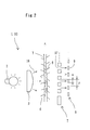
- FIG. 1 to 6 the following description will discuss one embodiment of the present invention.
- openings 17, formed in a slit 7, are allowed to correspond to layout positions of respective light-receiving elements 9.
- a traveling-speed measuring device (yarn speed sensor) 1 of a yarn to be installed in a winding device of the present invention is an optical system, and in this arrangement, when a yarn Y, which has a number of fluffs 6 the appearance of which is projected on the light-receiving elements 9, travels, a change in a photocurrent occurs, and this change is processed by using a so-called spatial filter principle so that, based upon the resulting value, the traveling speed and the yarn length are calculated.
- a plurality of strap-shaped light-receiving elements are aligned in a comb shape with equal intervals to form a pair of detectors; thus, a cyclic change in an electrical output that is detected each time a pattern or each portion of optical irregularities of the measured object, which appears on the light-receiving face of each of the light receiving elements, crosses the light-receiving element is observed and the number of repetitions within a specific time period is counted so that this is multiplied by a predetermined pitch corresponding to the layout pitch of the light-receiving elements; thus, the amount of movement and the speed of movement of the measured object (pattern or optical irregularities) in a direction virtually orthogonal to each of the light-receiving elements are found.
- the electrical output from the detector cyclically changes by a predetermined pitch corresponding to the layout pitch of the light-receiving elements each time the measured object and the detector are relatively moved.
- This phenomenon is caused by a narrow bandpass characteristic possessed by a transfer function of each of the light-receiving elements aligned with equal intervals as a spatial filter.
- light from the light source 2 is applied to the spun yarn Y through a diffusing lens 3.
- the light-receiving elements 9, each having a strap-shape having virtually the same width w, have the same photoelectric conversion characteristic, and in this example, these are connected in such a manner that outputs from the adj acent elements are taken out as one lot.
- the layout pitch p of the light-receiving elements 9 aligned with equal intervals is set to an interval that is preliminarily presumed as a repeated pattern of the fluffs 6 located in the yarn length direction.
- these patterns of the fluffs 6 and the like are statistically averaged when the traveling spun yarn Y is observed, and regarded as a repeated pattern with a predetermined interval.
- the respective light-receiving elements 9 are aligned with a pitch of about 5 mm.
- a slit 7 having openings 17 that correspond to layout positions of the respective light-receiving elements 9 is placed between the yarn Y and the light-receiving device 8 (respective light-receiving elements 9), as shown in Fig. 2, in order to prevent unnecessary diffused light or the like from being made incident thereon, and the following description will describe a case in which the yarn Y is allowed to travel in this state.
- the density difference of the shadow corresponding to the amounts of the fluffs 6 appearing on each of the light-receiving elements 9 also moves.
- the photocurrent outputted from the light-receiving elements 9 is changed due to the density difference .
- those which represent the density difference of shadows having a comparatively small interval and the density difference of shadows having a comparatively large interval with respect the layout pitch of the openings 17 of the slit 7, hardly appear on each of the element as a change in photocurrent; in contrast, those which represent the density difference of shadows having an interval (that is, a preliminarily assumed value as the layout interval between the fluffs 6, located in the yarn length direction) fits to the layout pitch of the openings 17 of the slit 7 cause a great change in the photocurrent in each of the elements (narrow bandpass characteristic possessed by a transfer function of a slit serving as a spatial filter or light-receiving elements aligned with equal intervals).
- the signal, extracted from the light-receiving elements 9, corresponds to a signal formed by extracting only the density difference of the shadow of a specific interval (the value preliminarily assumed as the repetitive pattern of the fluffs 6) that is determined by the optical system 10 and the layout of the light-receiving elements 9.
- the signal, obtained by the light-receiving elements 9, is waveform-shaped through a bandpass filter 19 in an operation unit 18 that is placed on the succeeding step of the light-receiving elements 9, and converted to a pulse train, and the number of pulses thereof is then counted by using a counter 15.
- the traveling speed of the yarn Y is calculated to be 1m/sec through calculations based upon the above-mentioned equation.
- the traveling speed and yarn length of the spun yarn Y found in this manner, are subjected to various processes in a control unit 14, and are then displayed on a display unit 13.
- the yarn traveling speed measuring device of the spatial filter system installed in the winding device of the present invention, is regarded as a system utilizing a phenomenon in which, when a human walking outside is viewed from the inside of a house through a reed bamboo blind, the human is partially viewed and shielded to appear as bright and dark portions of light.
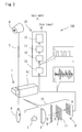
- the speed measuring device having the above-mentioned is installed in an automatic winder W shown in Fig. 4.
- the automatic winder W is a yarn-winding machine to be used in a finishing process of a spinning machine as well as in a preparing process for weaving and knitting operations, and the objective of this machine is to wind a spun yarn Y that has been wound around a spinning bobbin B in a spinning frame, not shown, in a preceding stage into a cone shape with a large size at high speeds, while removing portions causing defective yarn irregularities so as to be appropriately used in the succeeding stage.
- Fig. 4(A) shows the right side face of the automatic winder W and Fig. 4 (B) shows the front face including the main portion thereof, and the automatic winder W, which releases the yarn Y from the spinning bobbin B and again winds it as a package Q, is designed so that the yarn Y is released from the spinning bobbin B placed at a lower position, and sent upward; thus, the yarn Y is wound around the package Q so as to reach a predetermined diameter while being traversed by a traverse drum D.
- the package Q is supported by a cradle 20. On this cradle 20, the two sides of the package Q are fitted to and supported by bearing centers 20a and the bearing centers 20a are held by supporting arms 20b.
- a splicing device S is installed in the middle of a traveling passage of the yarn so that defective portions causing yarn irregularities can be removed as described above.
- the traverse drum D and the package Q are installed in parallel with each other, with being made in press-contact with each other; thus, the rotation of the traverse drum D serves as a driving source so that the package Q is driven to rotate.
- the yarn length wound around the package Q it becomes possible to accurately specify the yarn length wound around the package Q, and consequently to carry out yarn length control.
- the yarn length, wound around a package tends to have deviations of about ⁇ 1 % per package, although it depends on types of yarns and the like; however, in accordance with the automatic winder in which the speed-measuring device of a spun yarn of the spatial filter type is installed, the deviations can be reduced to a range within about ⁇ 0.3 % per package.
- the automatic winder of the present embodiment makes it possible to provide a package on which a yarn having a predetermined length has been wound; therefore, even in post-processes such as a warping process, it becomes possible to prevent some yarns from remaining in each of the packages, and consequently to eliminate wasteful use of yarns.
- the above-mentioned embodiment of the present invention has mainly discussed the structure for carrying out speed-measurements of a spun yarn to be wound by the automatic winder; however, the present invention is not intended to be limitedbytheabove-mentionedembodiment, andvariousdesigning modifications can be made.
- the speed-measuring device installed in the winding device of a spun yarn of the present invention, can be applied to various winding devices, such as a false twisting machine and a two-for-one twisting machine.
- the yarn length that has been wound around the package Q from the winding start point to the fully wound state can be found by using the measured traveling speed and winding time of the yarn; and, moreover, another structure in which, based upon these values, the yarn length is found in an accumulating manner by using an integrator or the like may be proposed.
- a light-shielding plate with through holes to be used for preventing diffused light from being made incident thereon may be further placed between the traveling yarn Y and the slit 7, and in the same manner as a generally-used spatial filter type speed detector, an objective lens may be further placed between the traveling yarn Y to be measured and the slit 7.
- an objective lens may be further placed between the traveling yarn Y to be measured and the slit 7.
- a shape, for example, disclosed in Japanese Patent Application Publication No. 62-34107 may be adopted.
- the layout pitch of the openings 17 of the slit 7 or the respective light-receiving elements 9 is not intended to be limited by the above-exemplified value.
- the slit 7, which has the openings 17 corresponding to the layout positions of the respective light-receiving elements 9, is placed between the object to be measured and the light-receiving elements 9; however, even when the slit is omitted, it is possible to measure the moving speed of the object.
- a plurality of light-receiving elements 9 are aligned with equal intervals in a comb shape to form a pair of light-receiving devices 8, and these are used as the spatial filter detector; however, by taking it into consideration that such a pair of comb-shaped detectors have dc components contained in the output, a differential spatial filter detector as shown in Fig. 5, in which two pairs of comb-shaped detectors are engaged with each other, may be used in order to remove the dc components.
- the layout pitch of the light-receiving elements 9 that constitute each of the pairs is indicated by p and the width of each of the light-receiving elements is indicated by w.
- Outputs, obtained from the respective detectors, are inputted to a differential amplifier 11, and after having been amplified by an amplifier 12, these are further inputted to the operation unit 18 that has been described earlier.
- a differential spatial filter detector it is possible to improve the bandpass characteristic in a low frequency band as indicated by a transfer function characteristic curve representing the performance of the light-receiving elements aligned with equal intervals as a spatial filter (see Fig. 6 (B)) so that a transfer function curve that has no low frequency pass characteristic is formed.
- a transfer function characteristic curve representing the performance of the light-receiving elements aligned with equal intervals as a spatial filter
- Fig. 6 shows transfer function characteristic curves P and P' that indicate performances of the light-receiving elements that are aligned with equal intervals as a spatial filter.
- Fig. 6(A) shows the transfer function characteristic curve P that is possessed by a pair of comb-shaped detectors serving as a spatial filter, which are used in the respective examples
- Fig. 6 (B) shows the transfer function characteristic curve P' of the differential spatial filter detector.
- G(fx) represents a transfer function that indicates performance of the light-receiving elements aligned with equal intervals as a spatial filter
- fx represents a spatial frequency [cycle/centimeter] in the moving direction (x direction) of the object.
- the differential spatial filter detector makes it possible to exclude a bandpass characteristic in the low frequency band, with the narrow bandpass characteristic possessed by the transfer function of the light-receiving elements aligned with equal intervals as a spatial filter being maintained as it is.
- the narrow bandpass characteristic has 1/p as a central spatial frequency and 1/np as a bandwidth.
- p represents a layout pitch of the light-receiving elements constituting each of the pair
- n represents the total number of the light-receiving elements constituting each of the pair.
- the present invention makes it possible to provide a winding device of a spun yarn having a speed-measuring device which has an inexpensive, simple and accurate structure in which the basic principle of a spatial filter capable of optically measuring a speed of an object in a non-contact state is utilized.
- the traveling speed of a spun yarn can be measure with high precision in a non-contact state, and by using the resulting value, the yarn length, wound around a package, is calculated so that an accurate yarn length controlling process can be carried out. Further, it becomes possible to provide packages each of which has a yarn with a predetermined length wound thereon; therefore, even in the post processes such as a warping process, it becomes possible to prevent some yarns from remaining in each of the packages, and consequently to eliminate wasteful use of yarns.
Landscapes
- Engineering & Computer Science (AREA)
- Textile Engineering (AREA)
- Physics & Mathematics (AREA)
- General Physics & Mathematics (AREA)
- Filamentary Materials, Packages, And Safety Devices Therefor (AREA)
- Spinning Or Twisting Of Yarns (AREA)
Abstract
Description
Consequently, since it is possible to easily satisfy the demand for a high-winding speed and also to carry out calculating processes for the traveling speed of a yarn without the necessity of using an expensive CPU so as to carry out complex calculations at high speeds, it becomes possible to suppress an increase in costs required for achieving a high winding speed.
Claims (3)
- A winding device, which winds a spun yarn while measuring a speed of the traveling spun yarn, comprising:wherein, when the spun yarn having a number of fluffs the appearance of which is projected on the light-receiving elements travels, based upon a change in a photocurrent, caused in response to the amount of fluffs, that occurs in the light-receiving elements, the speed of the traveling spinning yarn is found.light-receiving elements that are placed with equal intervals in a yarn traveling direction and convert incident light to an electric signal; anda projection light source that applies light to the spun yarn so as to project an image thereof on the light-receiving elements,
- The winding device according to claim 1, wherein:a device, which measures the speed of the spun yarn, comprises light-receiving elements that are placed with equal intervals in a yarn traveling direction and convert incident light to an electric signal; and a proj ection light source that applies light to the spun yarn so as to project an image thereof on the light-receiving elements, with the light-receiving elements being allowed to generate an electrical output that cyclically changes each time the light-receiving elements and the spun yarn are relatively moved by a predetermined pitch corresponding to the layout interval of the light-receiving elements, so that the device forms a spatial filter type speed detector that is arranged to find a speed of the traveling spun yarn by using the electrical output.
- The winding device according to claim 1 or claim 2, wherein: a yarn length of the wound spun yarn is found by using the measured traveling speed of the spun yarn and winding time required for winding the spun yarn so that the yarn length is regulated to a predetermined length.
Applications Claiming Priority (2)
| Application Number | Priority Date | Filing Date | Title |
|---|---|---|---|
| JP2004000870 | 2004-01-06 | ||
| JP2004000870A JP4045444B2 (en) | 2004-01-06 | 2004-01-06 | Spinning yarn winding device |
Publications (2)
| Publication Number | Publication Date |
|---|---|
| EP1553037A1 true EP1553037A1 (en) | 2005-07-13 |
| EP1553037B1 EP1553037B1 (en) | 2009-05-27 |
Family
ID=34587662
Family Applications (1)
| Application Number | Title | Priority Date | Filing Date |
|---|---|---|---|
| EP20040028857 Expired - Lifetime EP1553037B1 (en) | 2004-01-06 | 2004-12-06 | Winding device of spun yarn |
Country Status (3)
| Country | Link |
|---|---|
| EP (1) | EP1553037B1 (en) |
| JP (1) | JP4045444B2 (en) |
| DE (1) | DE602004021229D1 (en) |
Cited By (7)
| Publication number | Priority date | Publication date | Assignee | Title |
|---|---|---|---|---|
| EP1795477A1 (en) * | 2005-12-08 | 2007-06-13 | Murata Kikai Kabushiki Kaisha | Winder |
| EP1795478A1 (en) | 2005-12-08 | 2007-06-13 | Murata Kikai Kabushiki Kaisha | Textile machine |
| EP2159180A3 (en) * | 2008-08-25 | 2010-12-29 | Murata Machinery, Ltd. | Yarn winding device and automatic winder |
| CN101659362B (en) * | 2008-08-25 | 2012-11-21 | 村田机械株式会社 | Yarn winding device and automatic winder with the same |
| CN103698549A (en) * | 2013-09-27 | 2014-04-02 | 苏州工业园区明益电器有限公司 | Sensor equipment for spinning machine |
| WO2014089714A3 (en) * | 2012-12-10 | 2014-08-07 | Uster Technologies Ag | Detection of a periodic structure in a moving elongated textile material |
| IT202300005847A1 (en) * | 2023-03-28 | 2024-09-28 | Savio Macch Tessili Spa | CONTINUOUS IMAGE ACQUISITION SYSTEM OF A THREAD DURING THE WINDING PHASE |
Families Citing this family (5)
| Publication number | Priority date | Publication date | Assignee | Title |
|---|---|---|---|---|
| JP5096180B2 (en) * | 2008-01-29 | 2012-12-12 | グンゼ株式会社 | Yarn running monitoring device |
| JP5126590B2 (en) * | 2008-02-14 | 2013-01-23 | 村田機械株式会社 | Yarn quality measuring instrument and yarn winding machine |
| JP2010112825A (en) * | 2008-11-06 | 2010-05-20 | Takenaka Electronic Industrial Co Ltd | Device for measuring traveling object to be inspected with the use of space filter |
| JP5357516B2 (en) * | 2008-11-07 | 2013-12-04 | グンゼ株式会社 | Yarn running monitoring device |
| CN102031605B (en) * | 2010-11-12 | 2012-03-14 | 刘瑜 | Detection method for spinning machine yarn state |
Citations (6)
| Publication number | Priority date | Publication date | Assignee | Title |
|---|---|---|---|---|
| JPS5342871A (en) | 1976-09-30 | 1978-04-18 | Akira Kobayashi | Method of measuring moving object by using air filter |
| JPS57154220A (en) * | 1981-03-17 | 1982-09-24 | Suteo Tsutsumi | Speed detecting space filter |
| CH669777A5 (en) * | 1986-02-28 | 1989-04-14 | Richard Allemann | Contactless thread length measuring circuit - scans speed proportional signals to derive part length and sums all part lengths to obtain overall length |
| EP0582112A1 (en) * | 1992-08-05 | 1994-02-09 | W. SCHLAFHORST AG & CO. | Apparatus for measuring the speed of a textile thread on a spooling machine |
| DE4434234A1 (en) * | 1994-09-24 | 1996-03-28 | Schlafhorst & Co W | Measuring system for determining speed of textile material moving longitudinally |
| DE19900581A1 (en) | 1999-01-09 | 2000-07-27 | Univ Dresden Tech | Non-contact measurement of yarn speed or running length uses grid rods in a structured electrode array to give signals from the yarn electrostatic charge to be processed to display the speed/length values |
-
2004
- 2004-01-06 JP JP2004000870A patent/JP4045444B2/en not_active Expired - Lifetime
- 2004-12-06 DE DE200460021229 patent/DE602004021229D1/en not_active Expired - Lifetime
- 2004-12-06 EP EP20040028857 patent/EP1553037B1/en not_active Expired - Lifetime
Patent Citations (8)
| Publication number | Priority date | Publication date | Assignee | Title |
|---|---|---|---|---|
| JPS5342871A (en) | 1976-09-30 | 1978-04-18 | Akira Kobayashi | Method of measuring moving object by using air filter |
| JPS57154220A (en) * | 1981-03-17 | 1982-09-24 | Suteo Tsutsumi | Speed detecting space filter |
| CH669777A5 (en) * | 1986-02-28 | 1989-04-14 | Richard Allemann | Contactless thread length measuring circuit - scans speed proportional signals to derive part length and sums all part lengths to obtain overall length |
| EP0582112A1 (en) * | 1992-08-05 | 1994-02-09 | W. SCHLAFHORST AG & CO. | Apparatus for measuring the speed of a textile thread on a spooling machine |
| JPH06186242A (en) * | 1992-08-05 | 1994-07-08 | Bee Shiyuraafuhorusuto & Co | Fiber-thread-speed measuring device of winding apparatus |
| DE4434234A1 (en) * | 1994-09-24 | 1996-03-28 | Schlafhorst & Co W | Measuring system for determining speed of textile material moving longitudinally |
| JPH08105909A (en) * | 1994-09-24 | 1996-04-23 | Bee Shiyuraafuhorusuto & Co | Device for determining speed of spun yarn running in longitudinal direction |
| DE19900581A1 (en) | 1999-01-09 | 2000-07-27 | Univ Dresden Tech | Non-contact measurement of yarn speed or running length uses grid rods in a structured electrode array to give signals from the yarn electrostatic charge to be processed to display the speed/length values |
Non-Patent Citations (4)
| Title |
|---|
| BACKMANN R ET AL: "BERUEHRUNGSLOSE GESCHWINDIGKEITSMESSUNG AM LAUFENDEN FADEN", MELLIAND TEXTILBERICHTE, INTERNATIONAL TEXTILE REPORTS, MELLIAND TEXTILBERICHTE K.G. HEIDELBERG, DE, vol. 74, no. 7, 1 July 1993 (1993-07-01), pages 639 - 640, XP000377924, ISSN: 0341-0781 * |
| BACKMANN, R. ET AL.: "Berührungslose Geschwindigkeitsmessung am laufenden Faden", MELLIAND TEXTILBERICHTE, INTERNATIONAL TEXTILE REPORTS, MELLIAND TEXTILBERICHTE K.G., vol. 74, no. 7, 1 July 1993 (1993-07-01), pages 639 - 640 |
| PATENT ABSTRACTS OF JAPAN vol. 006, no. 258 (P - 163) 17 December 1982 (1982-12-17) * |
| PATENT ABSTRACTS OF JAPAN vol. 1998, no. 07 31 March 1998 (1998-03-31) * |
Cited By (10)
| Publication number | Priority date | Publication date | Assignee | Title |
|---|---|---|---|---|
| EP1795477A1 (en) * | 2005-12-08 | 2007-06-13 | Murata Kikai Kabushiki Kaisha | Winder |
| EP1795478A1 (en) | 2005-12-08 | 2007-06-13 | Murata Kikai Kabushiki Kaisha | Textile machine |
| EP2159180A3 (en) * | 2008-08-25 | 2010-12-29 | Murata Machinery, Ltd. | Yarn winding device and automatic winder |
| CN101659362B (en) * | 2008-08-25 | 2012-11-21 | 村田机械株式会社 | Yarn winding device and automatic winder with the same |
| CN101659361B (en) * | 2008-08-25 | 2012-11-28 | 村田机械株式会社 | Yarn winding device and automatic winder with the same |
| WO2014089714A3 (en) * | 2012-12-10 | 2014-08-07 | Uster Technologies Ag | Detection of a periodic structure in a moving elongated textile material |
| CN105308440A (en) * | 2012-12-10 | 2016-02-03 | 乌斯特技术股份公司 | Detection of a periodic structure in a moving elongated textile material |
| CN103698549A (en) * | 2013-09-27 | 2014-04-02 | 苏州工业园区明益电器有限公司 | Sensor equipment for spinning machine |
| CN103698549B (en) * | 2013-09-27 | 2016-10-05 | 苏州工业园区明益电器有限公司 | A kind of used in spinning machine sensor device |
| IT202300005847A1 (en) * | 2023-03-28 | 2024-09-28 | Savio Macch Tessili Spa | CONTINUOUS IMAGE ACQUISITION SYSTEM OF A THREAD DURING THE WINDING PHASE |
Also Published As
| Publication number | Publication date |
|---|---|
| JP2005194024A (en) | 2005-07-21 |
| EP1553037B1 (en) | 2009-05-27 |
| JP4045444B2 (en) | 2008-02-13 |
| DE602004021229D1 (en) | 2009-07-09 |
Similar Documents
| Publication | Publication Date | Title |
|---|---|---|
| EP1553037B1 (en) | Winding device of spun yarn | |
| WO1999036746A1 (en) | A method of determining the thickness and/or the homogeneity of a moving linear textile formation and a device for carrying out the method | |
| EP0213587B1 (en) | Broken filament detector and system therefor | |
| CN113727928B (en) | Method for non-contact optical detection of yarn at a workstation of a yarn manufacturing textile machine, yarn optical sensor and textile machine | |
| CN101659362B (en) | Yarn winding device and automatic winder with the same | |
| JPH10115565A (en) | Apparatus for measuring thread tension of running thread | |
| US7057197B2 (en) | Method and device for contactless measurement of a linear textile formation such as yarn etc | |
| CN104860114A (en) | Yarn Coiling Device | |
| JPS61221063A (en) | Yarn breakage detection method for yarn array and feeler used therein | |
| JP4819227B2 (en) | Device for detecting the movement and / or presence of a fiber sliver | |
| US20100107590A1 (en) | Device for producing a rope lap | |
| WO1979000010A1 (en) | Plural sensor ends down detecting apparatus | |
| ITMI951958A1 (en) | DEVICE FOR DETERMINING THE SPEED OF A TEXTILE PRODUCT MOVED IN THE DIRECTION OF ITS LONGITUDINAL EXTENSION, IN PARTICULAR | |
| JPH0327470B2 (en) | ||
| JPS61254473A (en) | Spindle driven winder | |
| CN100582340C (en) | Device for detecting difference in warp tension of a loom | |
| JPS5945783B2 (en) | Interlace yarn entanglement degree measuring device | |
| Townsend | Weft tension in weaving | |
| JPH0526516B2 (en) | ||
| JPS5916377Y2 (en) | Twill winding machine | |
| JPH0328047Y2 (en) | ||
| JP6800497B1 (en) | Defect detection device for striatum | |
| JPH0215897Y2 (en) | ||
| CN118424118A (en) | A kind of bobbin yarn precision length fixing device and length fixing method of winding machine | |
| JPS58207255A (en) | Abnormality sensing method for threads |
Legal Events
| Date | Code | Title | Description |
|---|---|---|---|
| PUAI | Public reference made under article 153(3) epc to a published international application that has entered the european phase |
Free format text: ORIGINAL CODE: 0009012 |
|
| AK | Designated contracting states |
Kind code of ref document: A1 Designated state(s): AT BE BG CH CY CZ DE DK EE ES FI FR GB GR HU IE IS IT LI LT LU MC NL PL PT RO SE SI SK TR |
|
| AX | Request for extension of the european patent |
Extension state: AL BA HR LV MK YU |
|
| 17P | Request for examination filed |
Effective date: 20050628 |
|
| AKX | Designation fees paid |
Designated state(s): DE IT |
|
| 17Q | First examination report despatched |
Effective date: 20060124 |
|
| GRAP | Despatch of communication of intention to grant a patent |
Free format text: ORIGINAL CODE: EPIDOSNIGR1 |
|
| GRAS | Grant fee paid |
Free format text: ORIGINAL CODE: EPIDOSNIGR3 |
|
| GRAA | (expected) grant |
Free format text: ORIGINAL CODE: 0009210 |
|
| AK | Designated contracting states |
Kind code of ref document: B1 Designated state(s): DE IT |
|
| REF | Corresponds to: |
Ref document number: 602004021229 Country of ref document: DE Date of ref document: 20090709 Kind code of ref document: P |
|
| PLBE | No opposition filed within time limit |
Free format text: ORIGINAL CODE: 0009261 |
|
| STAA | Information on the status of an ep patent application or granted ep patent |
Free format text: STATUS: NO OPPOSITION FILED WITHIN TIME LIMIT |
|
| 26N | No opposition filed |
Effective date: 20100302 |
|
| PGFP | Annual fee paid to national office [announced via postgrant information from national office to epo] |
Ref country code: DE Payment date: 20231121 Year of fee payment: 20 |
|
| REG | Reference to a national code |
Ref country code: DE Ref legal event code: R071 Ref document number: 602004021229 Country of ref document: DE |
|
| PGFP | Annual fee paid to national office [announced via postgrant information from national office to epo] |
Ref country code: IT Payment date: 20231121 Year of fee payment: 20 |