EP1552986A1 - Support structure for an interior overhead console of panoramic roofs of automotive vehicles - Google Patents
Support structure for an interior overhead console of panoramic roofs of automotive vehicles Download PDFInfo
- Publication number
- EP1552986A1 EP1552986A1 EP04380003A EP04380003A EP1552986A1 EP 1552986 A1 EP1552986 A1 EP 1552986A1 EP 04380003 A EP04380003 A EP 04380003A EP 04380003 A EP04380003 A EP 04380003A EP 1552986 A1 EP1552986 A1 EP 1552986A1
- Authority
- EP
- European Patent Office
- Prior art keywords
- trays
- compartments
- assembly
- crosspieces
- roof
- Prior art date
- Legal status (The legal status is an assumption and is not a legal conclusion. Google has not performed a legal analysis and makes no representation as to the accuracy of the status listed.)
- Granted
Links
Images


Classifications
-
- B—PERFORMING OPERATIONS; TRANSPORTING
- B60—VEHICLES IN GENERAL
- B60R—VEHICLES, VEHICLE FITTINGS, OR VEHICLE PARTS, NOT OTHERWISE PROVIDED FOR
- B60R7/00—Stowing or holding appliances inside vehicle primarily intended for personal property smaller than suit-cases, e.g. travelling articles, or maps
- B60R7/04—Stowing or holding appliances inside vehicle primarily intended for personal property smaller than suit-cases, e.g. travelling articles, or maps in driver or passenger space, e.g. using racks
-
- B—PERFORMING OPERATIONS; TRANSPORTING
- B60—VEHICLES IN GENERAL
- B60R—VEHICLES, VEHICLE FITTINGS, OR VEHICLE PARTS, NOT OTHERWISE PROVIDED FOR
- B60R11/00—Arrangements for holding or mounting articles, not otherwise provided for
-
- B—PERFORMING OPERATIONS; TRANSPORTING
- B60—VEHICLES IN GENERAL
- B60R—VEHICLES, VEHICLE FITTINGS, OR VEHICLE PARTS, NOT OTHERWISE PROVIDED FOR
- B60R13/00—Elements for body-finishing, identifying, or decorating; Arrangements or adaptations for advertising purposes
- B60R13/02—Internal Trim mouldings ; Internal Ledges; Wall liners for passenger compartments; Roof liners
- B60R13/0212—Roof or head liners
- B60R13/0225—Roof or head liners self supporting head liners
-
- B—PERFORMING OPERATIONS; TRANSPORTING
- B60—VEHICLES IN GENERAL
- B60R—VEHICLES, VEHICLE FITTINGS, OR VEHICLE PARTS, NOT OTHERWISE PROVIDED FOR
- B60R13/00—Elements for body-finishing, identifying, or decorating; Arrangements or adaptations for advertising purposes
- B60R13/02—Internal Trim mouldings ; Internal Ledges; Wall liners for passenger compartments; Roof liners
- B60R13/0212—Roof or head liners
- B60R13/0231—Roof or head liners specially adapted for roofs with openings
-
- B—PERFORMING OPERATIONS; TRANSPORTING
- B60—VEHICLES IN GENERAL
- B60R—VEHICLES, VEHICLE FITTINGS, OR VEHICLE PARTS, NOT OTHERWISE PROVIDED FOR
- B60R11/00—Arrangements for holding or mounting articles, not otherwise provided for
- B60R2011/0001—Arrangements for holding or mounting articles, not otherwise provided for characterised by position
- B60R2011/0003—Arrangements for holding or mounting articles, not otherwise provided for characterised by position inside the vehicle
- B60R2011/0028—Ceiling, e.g. roof rails
Definitions
- the present invention refers to a support structure for an interior overhead console of panoramic roofs of automotive vehicles, constituted such that it allows safe assembly of said console, as well as the arrangement of interchangeable compartments.
- Overhead consoles of vehicles constitute the means for arranging different accessories, such as lights, switches, speakers, etc., for services of the compartment or interior in which the console is arranged.
- the object of the present invention is a support structure for an interior overhead console of automotive vehicles, constituted such that its anchoring is carried out on the resistant elements of the vehicle roof, and such that the trim not only undergoes no stress coming from said console, but that it is even partially supported by it.
- Another object of the invention is to develop a structure allowing the interchangeability of the components or elements thereof.
- a further object of the invention is to achieve a console assembly system, by means of which the structural components of the roof, and of the structure by means of which the console is assembled, remain hidden.
- the trays are provided on their smaller walls with coupling means for coupling onto the crosspiece, and are provided on said walls and on the bottom with holes for the passage of pre-assembly and fixing elements for fixing to the crosspieces.
- the purpose of the pre-assembly elements is to place the part in its final position by means of a correct positioning and non-permanent anchoring, facilitating the task of fixing the part.
- the pre-assembly elements can vary: centering devices, clips, tabs, etc.
- One combination for the tray described includes centering devices and clips.
- the purpose of the fixing elements is to permanently anchor the part in its final position.
- the fixing elements can be: screws, clips, adhesives, rivets, etc. Screws are included as the fixing elements for the tray described.
- the trays will be arranged with the open wall towards the interior of the vehicle, and will be finished with an outer flange on which a decorative frame is fixed, between which frame and said flange the trim of the roof will be retained, such that the structure of the invention, through this frame, serves as a retention element and partially as a support element of the trim of the roof, without transmitting to it any action or effect due to the weight of the structure itself and console, nor due to the actions or manipulations which may be carried out on said console.
- the constitution set forth allows the interchangeability of the compartments which are assembled in the trays and which will bear the different accessories.
- tray assembly and removal can be carried out from the interior of the vehicle, since its fixing to the crosspieces is carried out by means of easily accessible screws.
- These trays are completely hidden by means of the compartments bearing the accessories and by means of the decorative frame, and partially by the trim of the roof of the vehicle.
- Fastening of the compartments is also carried out by means of screws which can be operated from the interior of the vehicle, such that the interchangeability of such compartments can be carried out even by the user of the vehicle.
- the trays will preferably be constituted of the basis of a light metal alloy and can adopt an approximately rectangular right prismatic configuration, open at one of their larger walls.
- the number of trays making up the structure will vary, depending on the vehicle type.
- the trays rest on the crosspieces between which the trays are arranged through the bottom of one of its ends and also through the adjacent smaller wall, the support areas being provided with holes facing holes of the crosspieces for the passage of centering devices, fastening clips and lockscrews.
- the structure of the invention allows anchoring interchangeable compartments, even those having different configurations, assembling and removing these compartments from the interior of the vehicle, as previously indicated.
- the trays are provided with anchorings or metal inserts for fastening the compartments.
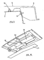
- the support structure of the console shown in the drawings consists of two trays, referenced with numbers 1 and 2, carried out in a light metal alloy material, which are open at one of their larger walls, the one which is facing the interior of the vehicle.
- the tray 1 is assembled between the front crosspiece 3 and intermediate crosspiece 4 of the roof 5 of the vehicle, whereas the tray 2 is assembled between the intermediate crosspiece 4 and the rear crosspiece 6.
- these trays have an overall right rectangular prismatic configuration, open at one of the walls or base and can include intermediate reinforcement partitions 7, as well as a flange or tabs 8 from one of the smaller walls, designed to rest on the intermediate crosspiece 4, as will be explained below.
- the trays 1 and 2 are aligned in the lengthwise direction of the vehicle, and their number can vary depending on the features or dimensions of said vehicle. In the example shown in the drawings, the tray 1 will correspond to the front half of the vehicle and tray 2 to the rear half.
- the trays 1 and 2 can rest on the crosspieces in which they concur through their smaller walls, through the closed bottom or both, these support areas including coupling means or shaping for coupling onto the crosspieces, as well as holes for the passage of centering devices 9 for centering the trays to the crosspiece, tray fastening clips 10 and holes 11 for the passage of lockscrews.
- the centering devices 9 and clips 10 serve as pre-assembly elements, said assembly being secured by the lockscrews.
- the bottom of the trays is also provided with holes 12 for centering the interchangeable compartments assembled inside the trays, as will be explained below, and with holes 13 for the rapid fixing of these compartments.
- the trays are provided with a peripheral flange 14 where holes 15 have been made for anchoring a decorative frame, as will be explained in reference to figures 11 to 13.
- tray 1 is coupled onto the crosspiece by means of a transverse shaping or step 16, although in any case the tray 1 will lack such shaping or it will have a different shaping according to the shape of the area of the crosspiece 3 on which it rests and is coupled.
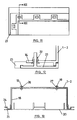
- Figure 5 shows one of the centering devices 9, fastening clips 10 and lockscrews 17 for fixing the tray to the crosspiece.
- Figure 6 shows one of the fastening clips 10. The remaining components are hidden in this view.
- Figure 7 shows two fastening clips 10 for fastening the front trays 1 and rear trays 2 to the central or intermediate crosspiece 4.
- Figures 8 and 9 show the meeting and fixing point where the tray 2 is fixed to the rear crosspiece 6.
- Figure 8 shows the centering device 9 for centering the tray 2 to the crosspiece 6, the fastening clips 10 and lockscrews 17.
- Figure 9 shows one of the fastening clips 10 and one of the lockscrews 17 for fixing the tray 2 to the crosspiece 6, these being self-tapping screws.
- the interchangeable compartments 18 are placed therein by means of the holes 13 of the trays, figure 2, for example with the aid of screws 19, figure 13.
- the interchangeable compartments 18 are closed by means of a cover 20.
- a decorative frame 21 is arranged around the trays, which frame, as seen in figures 11 and 12, is fixed to the peripheral flange 14 of the trays by means of clips 22 introduced through the holes 15 of the peripheral flange.
- the trim 23 of the roof can be partially introduced between the frame 21 and the peripheral flange 14.
- the frame 21 forms a peripheral groove 24 in which the trim 23 can be introduced.
- the assembly of compartments 18 occupying the trays 1 and 2 form the overhead console of the vehicle.
- the opening of the cover 20 of the interchangeable compartments can be carried out by any system, for example by means of a button or push-button forming part of the trays 1 and 2 themselves. Furthermore, the trays 1 and 2 can be provided on their internal surface, as seen in figure 4, with guides 26 ensuring correct positioning of the compartments in the trays.
- the lockscrews 19 of the compartments will not be fixed directly to the tray, but rather to metal inserts 27.
- the shapings of the trays in the coupling areas for coupling onto the crosspieces will depend on the shape of the crosspiece in the areas which the trays must be fixed on.
- the structure of the invention is specially designed for its application in panoramic roofs of vehicles.
Landscapes
- Engineering & Computer Science (AREA)
- Mechanical Engineering (AREA)
- Vehicle Step Arrangements And Article Storage (AREA)
- Body Structure For Vehicles (AREA)
Abstract
Description
Claims (6)
- A support structure for an interior overhead console of panoramic roofs of automotive vehicles, characterized in that it is constituted of one or more elongated trays (1-2), open at one of their larger walls, which are anchored to the crosspieces (3-4-6) of the roof (5) of the vehicle, defining housings for the assembly of interchangeable compartments (18); which trays are externally provided, from their smaller walls, with shapings (8-16) for coupling onto the crosspieces of the roof, as well as with holes for the passage of pre-assembly and fixing elements for fixing the trays to the crosspieces; the two trays further including an outer flange (14) which a decorative frame (21) is arranged and fixed on, between which frame and said flange the trim (23) of the roof is retained.
- A structure according to claim 1, characterized in that the trays (1-2) are constituted of a light metal alloy.
- A structure according to claim 1, characterized in that the trays (1-2) rest on the crosspieces (3-4-6) between which they are arranged through the bottom and adjacent smaller wall of said trays, being provided in the rest areas with holes facing holes of the crosspieces for the passage of the pre-assembly and fixing elements.
- A structure according to claim 3, characterized in that the pre-assembly and fixing elements include centering devices (9), fastening clips (10) and lockscrews (17).
- A structure according to claim 1, characterized in that the trays are provided with anchorings or metal inserts (27) for fastening the compartments (18), which allow the assembly and removal of said compartments from the interior of the vehicle.
- A structure according to claims 1 and 5, characterized in that the trays (1-2) are provided on their walls with guides (26) for the correct positioning of the compartments (18), and provided on the bottom with holes for the inserts (27) which the lockscrews (19) for fastening said compartments are screwed into.
Priority Applications (6)
| Application Number | Priority Date | Filing Date | Title |
|---|---|---|---|
| EP04380003A EP1552986B1 (en) | 2004-01-08 | 2004-01-08 | Support structure for an interior overhead console of panoramic roofs of automotive vehicles |
| AT04380003T ATE350244T1 (en) | 2004-01-08 | 2004-01-08 | SUPPORT STRUCTURE FOR AN INTERIOR CONSOLE OF THE PANORAMIC ROOF OF A MOTOR VEHICLE |
| DE602004004054T DE602004004054T2 (en) | 2004-01-08 | 2004-01-08 | Support structure for an interior console of the panoramic roof of a motor vehicle |
| ES04380003T ES2279324T3 (en) | 2004-01-08 | 2004-01-08 | SUPPORT STRUCTURE FOR AN UPPER INTERIOR CONSOLE OF PANORAMIC CEILINGS OF MOTOR VEHICLES. |
| BR0404198-4A BRPI0404198A (en) | 2004-01-08 | 2004-09-30 | Support structure for a car sunroof aerial console |
| US11/031,377 US7055882B2 (en) | 2004-01-08 | 2005-01-07 | Support structure for an interior overhead console or panoramic roofs of automotive vehicles |
Applications Claiming Priority (1)
| Application Number | Priority Date | Filing Date | Title |
|---|---|---|---|
| EP04380003A EP1552986B1 (en) | 2004-01-08 | 2004-01-08 | Support structure for an interior overhead console of panoramic roofs of automotive vehicles |
Publications (2)
| Publication Number | Publication Date |
|---|---|
| EP1552986A1 true EP1552986A1 (en) | 2005-07-13 |
| EP1552986B1 EP1552986B1 (en) | 2007-01-03 |
Family
ID=34586025
Family Applications (1)
| Application Number | Title | Priority Date | Filing Date |
|---|---|---|---|
| EP04380003A Expired - Lifetime EP1552986B1 (en) | 2004-01-08 | 2004-01-08 | Support structure for an interior overhead console of panoramic roofs of automotive vehicles |
Country Status (6)
| Country | Link |
|---|---|
| US (1) | US7055882B2 (en) |
| EP (1) | EP1552986B1 (en) |
| AT (1) | ATE350244T1 (en) |
| BR (1) | BRPI0404198A (en) |
| DE (1) | DE602004004054T2 (en) |
| ES (1) | ES2279324T3 (en) |
Families Citing this family (14)
| Publication number | Priority date | Publication date | Assignee | Title |
|---|---|---|---|---|
| EP1501703B1 (en) * | 2002-04-29 | 2016-05-11 | Magna Mirrors Holding GmbH | Cover module |
| WO2004020249A2 (en) * | 2002-08-27 | 2004-03-11 | Johnson Controls Technology Company | Transparent vehicle roof with arrangement for receiving articles |
| US20070035161A1 (en) * | 2002-08-27 | 2007-02-15 | Johnson Controls Technology Company | Overhead system for a vehicle |
| JP4244853B2 (en) * | 2004-04-22 | 2009-03-25 | 豊田合成株式会社 | Console mounting structure |
| US7293816B2 (en) * | 2005-04-20 | 2007-11-13 | International Automotive Components Group North America, Inc. | Structural rail system for supporting an overhead console |
| US7677652B2 (en) * | 2006-03-29 | 2010-03-16 | Nissan Technical Center North America, Inc. | Roof inner body structure |
| US20080265629A1 (en) * | 2007-04-24 | 2008-10-30 | Lear Corporation | Headliner having a module |
| US8424961B2 (en) * | 2010-09-14 | 2013-04-23 | GM Global Technology Operations LLC | Aluminum roof panel for attachment to supporting steel vehicle body members |
| FR2998533B1 (en) * | 2012-11-27 | 2014-12-26 | Renault Sa | ROOF STRUCTURE OF A MOTOR VEHICLE |
| DE202013105134U1 (en) * | 2013-11-14 | 2013-11-25 | KDK Automotive GmbH | Arrangement for attaching a fitting part of a motor vehicle |
| DE102014104920B4 (en) * | 2013-11-19 | 2022-10-06 | Dr. Ing. H.C. F. Porsche Aktiengesellschaft | Body structure with roof rails |
| CN109958699A (en) | 2017-12-14 | 2019-07-02 | 福特环球技术公司 | Fasteners and Base Components |
| US20230242042A1 (en) * | 2022-02-02 | 2023-08-03 | Bcs Automotive Interface Solutions Us Llc | Overhead console and vehicle |
| CN115583205A (en) * | 2022-10-28 | 2023-01-10 | 郑州德福莱汽车科技有限公司 | A sunroof frame metal buckle buckle decoration panel structure |
Citations (6)
| Publication number | Priority date | Publication date | Assignee | Title |
|---|---|---|---|---|
| US4161336A (en) * | 1978-01-23 | 1979-07-17 | LeVan Specialty Co. Inc. | Dual-opening sun roof |
| US4738481A (en) * | 1986-02-13 | 1988-04-19 | Prince Corporation | Overhead console of a vehicle |
| US5105521A (en) * | 1988-06-10 | 1992-04-21 | United Technologies Automotive, Inc. | Method of assembling modular headliner to a vehicle by snap-fitting |
| US5303970A (en) * | 1992-12-03 | 1994-04-19 | Prince Corporation | Overhead console for a vehicle with a sunroof |
| US5667896A (en) * | 1995-04-11 | 1997-09-16 | Donnelly Corporation | Vehicle window assembly for mounting interior vehicle accessories |
| US6176536B1 (en) * | 1997-07-14 | 2001-01-23 | Lear Donnelly Overhead Systems L.L.C. | Vehicle soft console with interchangeable accessory bins and in-molded skin and fastener |
Family Cites Families (10)
| Publication number | Priority date | Publication date | Assignee | Title |
|---|---|---|---|---|
| US4818010A (en) * | 1986-10-17 | 1989-04-04 | Automotive Prototypes & Equipment | Mounting system for equipment in police vehicles |
| US4844533A (en) * | 1988-06-10 | 1989-07-04 | United Technologies Automotive, Inc. | Front lamp module and sunshade supports for modular headliner |
| US4867498A (en) * | 1988-12-02 | 1989-09-19 | Chivas Products Limited | Overhead console assembly |
| US5636891A (en) * | 1995-06-07 | 1997-06-10 | Prince Corporation | Adjustable fastener |
| US6338517B1 (en) * | 2000-01-20 | 2002-01-15 | Lear Corporation | Overhead console for a vehicle |
| US6669260B2 (en) * | 2001-05-01 | 2003-12-30 | Johnson Controls Technology Company | Modular system for a vehicle |
| US6827384B2 (en) * | 2001-05-01 | 2004-12-07 | Johnson Controls Technology Company | Modular system for a vehicle |
| US6575528B2 (en) * | 2001-10-19 | 2003-06-10 | Lear Corporation | Modular overhead console assembly |
| US6926333B2 (en) * | 2003-12-22 | 2005-08-09 | Lear Corporation | Modular overhead console assembly |
| US6957839B1 (en) * | 2004-09-24 | 2005-10-25 | Lear Corporation | Overhead console assembly |
-
2004
- 2004-01-08 DE DE602004004054T patent/DE602004004054T2/en not_active Expired - Fee Related
- 2004-01-08 AT AT04380003T patent/ATE350244T1/en not_active IP Right Cessation
- 2004-01-08 EP EP04380003A patent/EP1552986B1/en not_active Expired - Lifetime
- 2004-01-08 ES ES04380003T patent/ES2279324T3/en not_active Expired - Lifetime
- 2004-09-30 BR BR0404198-4A patent/BRPI0404198A/en not_active Application Discontinuation
-
2005
- 2005-01-07 US US11/031,377 patent/US7055882B2/en not_active Expired - Fee Related
Patent Citations (6)
| Publication number | Priority date | Publication date | Assignee | Title |
|---|---|---|---|---|
| US4161336A (en) * | 1978-01-23 | 1979-07-17 | LeVan Specialty Co. Inc. | Dual-opening sun roof |
| US4738481A (en) * | 1986-02-13 | 1988-04-19 | Prince Corporation | Overhead console of a vehicle |
| US5105521A (en) * | 1988-06-10 | 1992-04-21 | United Technologies Automotive, Inc. | Method of assembling modular headliner to a vehicle by snap-fitting |
| US5303970A (en) * | 1992-12-03 | 1994-04-19 | Prince Corporation | Overhead console for a vehicle with a sunroof |
| US5667896A (en) * | 1995-04-11 | 1997-09-16 | Donnelly Corporation | Vehicle window assembly for mounting interior vehicle accessories |
| US6176536B1 (en) * | 1997-07-14 | 2001-01-23 | Lear Donnelly Overhead Systems L.L.C. | Vehicle soft console with interchangeable accessory bins and in-molded skin and fastener |
Also Published As
| Publication number | Publication date |
|---|---|
| US7055882B2 (en) | 2006-06-06 |
| US20050212319A1 (en) | 2005-09-29 |
| EP1552986B1 (en) | 2007-01-03 |
| ATE350244T1 (en) | 2007-01-15 |
| DE602004004054T2 (en) | 2007-06-06 |
| DE602004004054D1 (en) | 2007-02-15 |
| ES2279324T3 (en) | 2007-08-16 |
| BRPI0404198A (en) | 2005-09-20 |
Similar Documents
| Publication | Publication Date | Title |
|---|---|---|
| EP1552986A1 (en) | Support structure for an interior overhead console of panoramic roofs of automotive vehicles | |
| US8113564B2 (en) | Vehicle console having molded side rails | |
| EP1338494B1 (en) | Vehicle instrument panel | |
| US6120091A (en) | Molded headliner with relatively rigid frame in combination with a less rigid mat | |
| US8322768B2 (en) | Variable length vehicle console | |
| US5005898A (en) | Vehicle structure and the method for its assembly | |
| CA2434441A1 (en) | Trim door hardware carrier and method of assembling vehicle door | |
| CA2551572C (en) | Trim door hardware carrier and methods of assembling vehicle door | |
| US20040084930A1 (en) | Trim hardware carrier | |
| KR100263132B1 (en) | Trough-like airbag housing | |
| US7481322B2 (en) | Rack for vehicles, preferably hat rack | |
| EP0716959B1 (en) | Modular vehicle package tray | |
| US20050270788A1 (en) | Lighting fixture frame and mounting panel apparatus | |
| US7389760B2 (en) | Modular engine cover | |
| ES2371741T3 (en) | FALSE ELEMENT OF AUTOMOTIVE VEHICLE FLOOR, FALSE FLOOR THAT INCLUDES SUCH ELEMENTS AND AUTOMOBILE VEHICLE SO EQUIPPED. | |
| JP2001328492A (en) | Vehicle roof groove cover member mounting structure | |
| US9346407B2 (en) | Snap-fit vehicle console assembly | |
| US6575495B2 (en) | Airbag mounting module | |
| JP6210933B2 (en) | Interior materials for vehicles | |
| JP2013032098A (en) | Door trim | |
| JP4296823B2 (en) | Vehicle ceiling structure | |
| JPH1134769A (en) | Bumper cover for automobile | |
| JP2003285667A (en) | Instrument panel | |
| JP2003285670A (en) | Instrument panel | |
| JP2003231446A (en) | Cover structure for interior equipment |
Legal Events
| Date | Code | Title | Description |
|---|---|---|---|
| PUAI | Public reference made under article 153(3) epc to a published international application that has entered the european phase |
Free format text: ORIGINAL CODE: 0009012 |
|
| AK | Designated contracting states |
Kind code of ref document: A1 Designated state(s): AT BE BG CH CY CZ DE DK EE ES FI FR GB GR HU IE IT LI LU MC NL PT RO SE SI SK TR |
|
| AX | Request for extension of the european patent |
Extension state: AL LT LV MK |
|
| 17P | Request for examination filed |
Effective date: 20051020 |
|
| AKX | Designation fees paid |
Designated state(s): AT BE BG CH CY CZ DE DK EE ES FI FR GB GR HU IE IT LI LU MC NL PT RO SE SI SK TR |
|
| GRAP | Despatch of communication of intention to grant a patent |
Free format text: ORIGINAL CODE: EPIDOSNIGR1 |
|
| GRAS | Grant fee paid |
Free format text: ORIGINAL CODE: EPIDOSNIGR3 |
|
| GRAA | (expected) grant |
Free format text: ORIGINAL CODE: 0009210 |
|
| RIN1 | Information on inventor provided before grant (corrected) |
Inventor name: SANTAOLALLA GIL, JOAQUIN Inventor name: LUGO RODRIGUEZ, OMAR Inventor name: HERRERO FUENTE, CARLOS |
|
| RAP1 | Party data changed (applicant data changed or rights of an application transferred) |
Owner name: GRUPO ANTOLIN-INGENIERIA, S.A. |
|
| AK | Designated contracting states |
Kind code of ref document: B1 Designated state(s): AT BE BG CH CY CZ DE DK EE ES FI FR GB GR HU IE IT LI LU MC NL PT RO SE SI SK TR |
|
| PG25 | Lapsed in a contracting state [announced via postgrant information from national office to epo] |
Ref country code: LI Free format text: LAPSE BECAUSE OF FAILURE TO SUBMIT A TRANSLATION OF THE DESCRIPTION OR TO PAY THE FEE WITHIN THE PRESCRIBED TIME-LIMIT Effective date: 20070103 Ref country code: CH Free format text: LAPSE BECAUSE OF FAILURE TO SUBMIT A TRANSLATION OF THE DESCRIPTION OR TO PAY THE FEE WITHIN THE PRESCRIBED TIME-LIMIT Effective date: 20070103 Ref country code: NL Free format text: LAPSE BECAUSE OF FAILURE TO SUBMIT A TRANSLATION OF THE DESCRIPTION OR TO PAY THE FEE WITHIN THE PRESCRIBED TIME-LIMIT Effective date: 20070103 Ref country code: SI Free format text: LAPSE BECAUSE OF FAILURE TO SUBMIT A TRANSLATION OF THE DESCRIPTION OR TO PAY THE FEE WITHIN THE PRESCRIBED TIME-LIMIT Effective date: 20070103 Ref country code: FI Free format text: LAPSE BECAUSE OF FAILURE TO SUBMIT A TRANSLATION OF THE DESCRIPTION OR TO PAY THE FEE WITHIN THE PRESCRIBED TIME-LIMIT Effective date: 20070103 Ref country code: DK Free format text: LAPSE BECAUSE OF FAILURE TO SUBMIT A TRANSLATION OF THE DESCRIPTION OR TO PAY THE FEE WITHIN THE PRESCRIBED TIME-LIMIT Effective date: 20070103 Ref country code: AT Free format text: LAPSE BECAUSE OF FAILURE TO SUBMIT A TRANSLATION OF THE DESCRIPTION OR TO PAY THE FEE WITHIN THE PRESCRIBED TIME-LIMIT Effective date: 20070103 |
|
| REG | Reference to a national code |
Ref country code: GB Ref legal event code: FG4D |
|
| PG25 | Lapsed in a contracting state [announced via postgrant information from national office to epo] |
Ref country code: IE Free format text: LAPSE BECAUSE OF NON-PAYMENT OF DUE FEES Effective date: 20070108 |
|
| PG25 | Lapsed in a contracting state [announced via postgrant information from national office to epo] |
Ref country code: MC Free format text: LAPSE BECAUSE OF NON-PAYMENT OF DUE FEES Effective date: 20070131 |
|
| REF | Corresponds to: |
Ref document number: 602004004054 Country of ref document: DE Date of ref document: 20070215 Kind code of ref document: P |
|
| REG | Reference to a national code |
Ref country code: IE Ref legal event code: FG4D |
|
| PG25 | Lapsed in a contracting state [announced via postgrant information from national office to epo] |
Ref country code: SE Free format text: LAPSE BECAUSE OF FAILURE TO SUBMIT A TRANSLATION OF THE DESCRIPTION OR TO PAY THE FEE WITHIN THE PRESCRIBED TIME-LIMIT Effective date: 20070403 |
|
| PG25 | Lapsed in a contracting state [announced via postgrant information from national office to epo] |
Ref country code: BG Free format text: LAPSE BECAUSE OF FAILURE TO SUBMIT A TRANSLATION OF THE DESCRIPTION OR TO PAY THE FEE WITHIN THE PRESCRIBED TIME-LIMIT Effective date: 20070404 |
|
| PG25 | Lapsed in a contracting state [announced via postgrant information from national office to epo] |
Ref country code: PT Free format text: LAPSE BECAUSE OF FAILURE TO SUBMIT A TRANSLATION OF THE DESCRIPTION OR TO PAY THE FEE WITHIN THE PRESCRIBED TIME-LIMIT Effective date: 20070604 |
|
| NLV1 | Nl: lapsed or annulled due to failure to fulfill the requirements of art. 29p and 29m of the patents act | ||
| REG | Reference to a national code |
Ref country code: CH Ref legal event code: PL |
|
| ET | Fr: translation filed | ||
| REG | Reference to a national code |
Ref country code: ES Ref legal event code: FG2A Ref document number: 2279324 Country of ref document: ES Kind code of ref document: T3 |
|
| PLBE | No opposition filed within time limit |
Free format text: ORIGINAL CODE: 0009261 |
|
| STAA | Information on the status of an ep patent application or granted ep patent |
Free format text: STATUS: NO OPPOSITION FILED WITHIN TIME LIMIT |
|
| PG25 | Lapsed in a contracting state [announced via postgrant information from national office to epo] |
Ref country code: SK Free format text: LAPSE BECAUSE OF FAILURE TO SUBMIT A TRANSLATION OF THE DESCRIPTION OR TO PAY THE FEE WITHIN THE PRESCRIBED TIME-LIMIT Effective date: 20070103 |
|
| 26N | No opposition filed |
Effective date: 20071005 |
|
| PG25 | Lapsed in a contracting state [announced via postgrant information from national office to epo] |
Ref country code: CZ Free format text: LAPSE BECAUSE OF FAILURE TO SUBMIT A TRANSLATION OF THE DESCRIPTION OR TO PAY THE FEE WITHIN THE PRESCRIBED TIME-LIMIT Effective date: 20070103 Ref country code: BE Free format text: LAPSE BECAUSE OF FAILURE TO SUBMIT A TRANSLATION OF THE DESCRIPTION OR TO PAY THE FEE WITHIN THE PRESCRIBED TIME-LIMIT Effective date: 20070103 Ref country code: RO Free format text: LAPSE BECAUSE OF FAILURE TO SUBMIT A TRANSLATION OF THE DESCRIPTION OR TO PAY THE FEE WITHIN THE PRESCRIBED TIME-LIMIT Effective date: 20070103 |
|
| PG25 | Lapsed in a contracting state [announced via postgrant information from national office to epo] |
Ref country code: IT Free format text: LAPSE BECAUSE OF FAILURE TO SUBMIT A TRANSLATION OF THE DESCRIPTION OR TO PAY THE FEE WITHIN THE PRESCRIBED TIME-LIMIT Effective date: 20070103 Ref country code: GR Free format text: LAPSE BECAUSE OF FAILURE TO SUBMIT A TRANSLATION OF THE DESCRIPTION OR TO PAY THE FEE WITHIN THE PRESCRIBED TIME-LIMIT Effective date: 20070404 |
|
| PGFP | Annual fee paid to national office [announced via postgrant information from national office to epo] |
Ref country code: ES Payment date: 20080111 Year of fee payment: 5 |
|
| PGFP | Annual fee paid to national office [announced via postgrant information from national office to epo] |
Ref country code: DE Payment date: 20080228 Year of fee payment: 5 |
|
| PGFP | Annual fee paid to national office [announced via postgrant information from national office to epo] |
Ref country code: FR Payment date: 20071228 Year of fee payment: 5 |
|
| GBPC | Gb: european patent ceased through non-payment of renewal fee |
Effective date: 20080108 |
|
| PG25 | Lapsed in a contracting state [announced via postgrant information from national office to epo] |
Ref country code: GB Free format text: LAPSE BECAUSE OF NON-PAYMENT OF DUE FEES Effective date: 20080108 |
|
| PG25 | Lapsed in a contracting state [announced via postgrant information from national office to epo] |
Ref country code: EE Free format text: LAPSE BECAUSE OF FAILURE TO SUBMIT A TRANSLATION OF THE DESCRIPTION OR TO PAY THE FEE WITHIN THE PRESCRIBED TIME-LIMIT Effective date: 20070103 |
|
| PG25 | Lapsed in a contracting state [announced via postgrant information from national office to epo] |
Ref country code: CY Free format text: LAPSE BECAUSE OF FAILURE TO SUBMIT A TRANSLATION OF THE DESCRIPTION OR TO PAY THE FEE WITHIN THE PRESCRIBED TIME-LIMIT Effective date: 20070103 |
|
| PG25 | Lapsed in a contracting state [announced via postgrant information from national office to epo] |
Ref country code: LU Free format text: LAPSE BECAUSE OF NON-PAYMENT OF DUE FEES Effective date: 20070108 |
|
| PG25 | Lapsed in a contracting state [announced via postgrant information from national office to epo] |
Ref country code: TR Free format text: LAPSE BECAUSE OF FAILURE TO SUBMIT A TRANSLATION OF THE DESCRIPTION OR TO PAY THE FEE WITHIN THE PRESCRIBED TIME-LIMIT Effective date: 20070103 Ref country code: HU Free format text: LAPSE BECAUSE OF FAILURE TO SUBMIT A TRANSLATION OF THE DESCRIPTION OR TO PAY THE FEE WITHIN THE PRESCRIBED TIME-LIMIT Effective date: 20070704 |
|
| PG25 | Lapsed in a contracting state [announced via postgrant information from national office to epo] |
Ref country code: DE Free format text: LAPSE BECAUSE OF NON-PAYMENT OF DUE FEES Effective date: 20090801 |
|
| REG | Reference to a national code |
Ref country code: FR Ref legal event code: ST Effective date: 20091030 |
|
| REG | Reference to a national code |
Ref country code: ES Ref legal event code: FD2A Effective date: 20090109 |
|
| PG25 | Lapsed in a contracting state [announced via postgrant information from national office to epo] |
Ref country code: FR Free format text: LAPSE BECAUSE OF NON-PAYMENT OF DUE FEES Effective date: 20090202 Ref country code: ES Free format text: LAPSE BECAUSE OF NON-PAYMENT OF DUE FEES Effective date: 20090109 |