EP1552182B1 - Canted coil springs various designs - Google Patents
Canted coil springs various designs Download PDFInfo
- Publication number
- EP1552182B1 EP1552182B1 EP03770517A EP03770517A EP1552182B1 EP 1552182 B1 EP1552182 B1 EP 1552182B1 EP 03770517 A EP03770517 A EP 03770517A EP 03770517 A EP03770517 A EP 03770517A EP 1552182 B1 EP1552182 B1 EP 1552182B1
- Authority
- EP
- European Patent Office
- Prior art keywords
- primary
- coils
- coil spring
- spring
- further characterized
- Prior art date
- Legal status (The legal status is an assumption and is not a legal conclusion. Google has not performed a legal analysis and makes no representation as to the accuracy of the status listed.)
- Expired - Lifetime
Links
- 230000001419 dependent effect Effects 0.000 description 1
- 238000012986 modification Methods 0.000 description 1
- 230000004048 modification Effects 0.000 description 1
Images

Classifications
-
- F—MECHANICAL ENGINEERING; LIGHTING; HEATING; WEAPONS; BLASTING
- F16—ENGINEERING ELEMENTS AND UNITS; GENERAL MEASURES FOR PRODUCING AND MAINTAINING EFFECTIVE FUNCTIONING OF MACHINES OR INSTALLATIONS; THERMAL INSULATION IN GENERAL
- F16F—SPRINGS; SHOCK-ABSORBERS; MEANS FOR DAMPING VIBRATION
- F16F1/00—Springs
- F16F1/02—Springs made of steel or other material having low internal friction; Wound, torsion, leaf, cup, ring or the like springs, the material of the spring not being relevant
- F16F1/04—Wound springs
- F16F1/045—Canted-coil springs
Definitions
- the present invention generally relates to canted-coil springs and more particularly, relates to canted-coil springs of various designs.
- the force-deflection characteristics of heretofore-available garter-type axial springs have been varied by changing numerous spring parameters, including the wire size, the coil height, the coil spacing, and the front and back angles. While these parameters can be used effectively to tailor the load-deflection characteristics of the spring, they do not dominate or enable the spring to achieve its total design potential.
- the selected disposition of the back angle and trailing portions defined thereby provides for the capability of tailoring a garter-type axially resilient coil spring beyond the range of conventional garter-type resilient coil springs heretofore known.
- springs may be formulated with higher load-deflection characteristics. That is, the spring is able to exert a greater force in response to a given deflection than a spring having the same dimensions and wire size with a trailing portion along the inside diameter of the spring.
- these springs can be fabricated from smaller wire and have a closer coil spacing, while still exerting the same force in response to deflection as prior art springs.
- the present invention is related to the discovery of other parameters which can be utilized to design garter-type springs having selected load-deflection characteristics.
- a spring in accordance with the present invention, provides operational load-deflection characteristics which may be used to advantage in the design of springs for applications heretofore not possible.
- WO 99/49233 discloses torsional vibration damper comprising energy storing devices designed as straight pressure coil springs.
- the energy storing devices comprise coils with smaller diameter and coils with larger diameter which alternate.
- a coil spring in accordance with the present invention generally includes a plurality of primary wire coils and a plurality of secondary wire coils.
- the primary and secondary wire coils are contiguous and differentiated by a dimensional size in order to provide variable force and variable deflection.
- the primary and secondary coils may also be disposed in an eccentric manner about the spring centerline in order to tailor the variable force and variable deflection provided by the coils.
- Various combinations of coil types may also be utilized as hereinafter discussed.
- the secondary coils may have a smaller diameter than the diameter of the primary coils and the primary and the secondary coils may be either concentric or eccentric.
- the coils may be canted and have various cross-sections, such as elliptical, round, rectangular, square, triangular or "D" shaped.
- the primary and secondary coils may have differing shapes.
- helical coils may be utilized and the secondary coils may be formed of a heavier gauge wire than the wire gauge of the primary coils.
- the coils may have constant canting or variable canting and the primary and secondary coils may be disposed in an alternating pattern along the centerline.
- a garter spring may be formed by joining ends of the primary and secondary coils and the primary coils and secondary coils may be disposed with a concave turn-angle within the garter spring or a convex turn-angle. Both radial and axial springs may be utilized in accordance with the present invention.
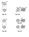
- Figure 1A shows a garter-type spring 554 having radial primary coils 556 with axial secondary coils 558 disposed therein.
- Figure 1B includes a side view of the spring 554 showing the manner in which the coils are positioned in a longitudinal manner.
- Figure 2A - 2C illustrates springs 578, 586 with various positionings of primary and secondary coils.
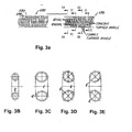
- Figure 3A shows a combination concave/convex turn-angle spring 590 having primary and second coils 592, 594 and Figures 3B - 3E show various end views taken along the lines indicated in Figure 3A.
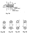
- Figure 4A shows a combination of offset radial, axial concave turn-angle and convex turn-angle spring 600 having primary and secondary coils 602, 604 as indicated in Figure 4A.
- Figures 4B - 4E are cross-sectional views taken along the lines as indicated in Figure 4A.
- Figures 5A - 5E show the spring 610 having round primary and secondary coils 612 and 614. This should be compared with Figures 4A - 4E in which spring 600 includes elliptical primary and secondary coils 602, 604, and a combination of radial and axial concave turn-angle and convex turn-angle.
- Figures 5A - 5E show cross-sections of the spring 610 taken along the lines as indicated in Figure 5A.
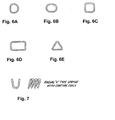
- Figures 6A - 6E and Figure 7 show various cross-sectional views of primary and secondary coils, which may be utilized in the hereinabove described configuration of springs.
Landscapes
- Engineering & Computer Science (AREA)
- General Engineering & Computer Science (AREA)
- Mechanical Engineering (AREA)
- Springs (AREA)
Abstract
Description
- The present invention generally relates to canted-coil springs and more particularly, relates to canted-coil springs of various designs.
- A general discussion of these types of canted-coil garter-type springs and further advancement in spring design is set forth in U.S. Patent Nos. 4,655,462; 4,826,144; 4,830,344; 4,893,795; 4,876,781; 4,907,788; 4,915,366; 4,961,253; 4,974,821; 4,964,204; 5,160,122; 5,108,078; 5,139,243; 5,139,276; 5,203,849; 5,239,737; 5,503,375; 5,615,870; 5,709,371; 5,791,638 to Balsells.
- The force-deflection characteristics of heretofore-available garter-type axial springs have been varied by changing numerous spring parameters, including the wire size, the coil height, the coil spacing, and the front and back angles. While these parameters can be used effectively to tailor the load-deflection characteristics of the spring, they do not dominate or enable the spring to achieve its total design potential.
- A heretofore-unrecognized parameter substantially affecting the performance of garter-type axial loaded springs, is set forth in U.S. Patent Nos. 4,826,144 and 4,915,366. These references disclose coils which are interconnected in a manner forming a garter-type resilient coil spring, with the trailing portion along an outside diameter of the garter-type axially resilient coil spring, and the leading portion along an inside diameter of the garter-type axially resilient coil spring and vice-versa.
- The selected disposition of the back angle and trailing portions defined thereby provides for the capability of tailoring a garter-type axially resilient coil spring beyond the range of conventional garter-type resilient coil springs heretofore known.
- As a consequence, springs may be formulated with higher load-deflection characteristics. That is, the spring is able to exert a greater force in response to a given deflection than a spring having the same dimensions and wire size with a trailing portion along the inside diameter of the spring.
- As a result, these springs can be fabricated from smaller wire and have a closer coil spacing, while still exerting the same force in response to deflection as prior art springs.
- The present invention is related to the discovery of other parameters which can be utilized to design garter-type springs having selected load-deflection characteristics.
- A spring, in accordance with the present invention, provides operational load-deflection characteristics which may be used to advantage in the design of springs for applications heretofore not possible.
- WO 99/49233 discloses torsional vibration damper comprising energy storing devices designed as straight pressure coil springs. The energy storing devices comprise coils with smaller diameter and coils with larger diameter which alternate.
- A coil spring in accordance with the invention is described in
claim 1. Advantageous embodiments are described in the dependent claims. - A coil spring in accordance with the present invention generally includes a plurality of primary wire coils and a plurality of secondary wire coils. The primary and secondary wire coils are contiguous and differentiated by a dimensional size in order to provide variable force and variable deflection.
- In addition, the primary and secondary coils may also be disposed in an eccentric manner about the spring centerline in order to tailor the variable force and variable deflection provided by the coils. Various combinations of coil types may also be utilized as hereinafter discussed.
- In various embodiments of the present invention, the secondary coils may have a smaller diameter than the diameter of the primary coils and the primary and the secondary coils may be either concentric or eccentric.
- Further, the coils may be canted and have various cross-sections, such as elliptical, round, rectangular, square, triangular or "D" shaped.
- In addition, the primary and secondary coils may have differing shapes. Further, helical coils may be utilized and the secondary coils may be formed of a heavier gauge wire than the wire gauge of the primary coils.
- The coils may have constant canting or variable canting and the primary and secondary coils may be disposed in an alternating pattern along the centerline.
- A garter spring may be formed by joining ends of the primary and secondary coils and the primary coils and secondary coils may be disposed with a concave turn-angle within the garter spring or a convex turn-angle. Both radial and axial springs may be utilized in accordance with the present invention.
- The advantages and teachers of the present invention will appear from the following description when considered in conjunction with the accompanying drawings in which:
- Figures 1A - 1B show canted spring elliptical coils with a combination of radial and axial coils that form a length or ring, or garter, spring;
- Figures 2A - 2C show a canted spring with elliptical, eccentric offset centered coils with a combination radial and axial coils in length;
- Figures 3A - 3E show combinations of radial, axial, concave and convex turn-angles with elliptical coils canting along the minor axis, the spring being shown in length;
- Figures 4A - 4E show a combination of offset radial, axial, concave, convex turn-angle spring with elliptical coils offset on one side with canting along the minor axis, the spring being shown in length;
- Figures 5A - 5E show a combination of radial, axial, concave/convex turn-angles spring with round coils offset on one side with canting along the minor axis, spring being shown in the length;
- Figures 6A - 6E show various cross-sections of the coils, which may be utilized in accordance with the present invention;
- Figure 7 is a view of a radial "V" type spring with canting coils suitable for use in accordance with the present invention.
- Figure 1A shows a garter-
type spring 554 having radial primary coils 556 with axialsecondary coils 558 disposed therein. - Figure 1B includes a side view of the
spring 554 showing the manner in which the coils are positioned in a longitudinal manner. - Figure 2A - 2C illustrates
springs - Figure 3A shows a combination concave/convex turn-
angle spring 590 having primary andsecond coils 592, 594 and Figures 3B - 3E show various end views taken along the lines indicated in Figure 3A. - Figure 4A shows a combination of offset radial, axial concave turn-angle and convex turn-
angle spring 600 having primary andsecondary coils - Figures 4B - 4E are cross-sectional views taken along the lines as indicated in Figure 4A.
- Figures 5A - 5E show the spring 610 having round primary and
secondary coils spring 600 includes elliptical primary andsecondary coils - Figures 5A - 5E show cross-sections of the spring 610 taken along the lines as indicated in Figure 5A.
- Figures 6A - 6E and Figure 7 show various cross-sectional views of primary and secondary coils, which may be utilized in the hereinabove described configuration of springs.
- Although there has been hereinabove described specific coil spring in accordance with the present invention for the purpose of illustrating the manner in which the invention may be used to advantage, it should be appreciated that the invention is not limited thereto. That is, the present invention may suitably comprise, consist of, or consist essentially of the recited elements. Further, the invention illustratively disclosed herein suitably may be practiced in the absence of any element, which is not specifically disclosed herein. Accordingly, any and all modifications, variations or equivalent arrangements, which may occur to those skilled in the art, should be considered to be within the scope of the present invention as defined in the appended claims.
Claims (10)
- A coil spring (554; 578; 590; 600; 610) comprising:a plurality of primary wire coils (556; 592; 602; 612); anda plurality of secondary wire coils (558; 594; 604; 614), the primary and secondary coils (556; 592; 602; 612; 558; 594; 604; 614) being contiguous and differentiated from one another by a dimensional size in order to provide variable force and variable deflection, the coil spring (554; 578; 590; 600; 610) characterized by the primary and secondary coils (556; 592; 602; 612; 558; 594; 604; 614) being joined to form a garter spring wherein the primary coil (556; 592; 602; 612) is radial and the secondary coil (558; 594; 604; 614) is axial.
- The coil spring according to claim 1, characterized by the secondary wire coils (558; 594; 604; 614) being disposed between adjoining and contiguous primary wire coils (556; 592; 602; 612).
- The coil spring according to claim 1 or 2 further characterized in that the secondary spring (558; 594; 604; 614) is disposed with a concave turn-angle within the garter spring.
- The coil spring according to claim 1 or 2 further characterized in that the secondary spring (558; 594; 604; 614) is disposed with a convex turn-angle within the garter spring.
- The coil spring according to claim 1 or 2 further characterized in that at least one of the primary and secondary coils (556; 592; 602; 612; 558; 594; 604; 614) has a D cross-section.
- The coil spring according to claim 1 or 2 further characterized in that at least one of the primary and secondary coils (556; 592; 602; 612; 558; 594; 604; 614) has a square cross-section.
- The coil spring according to claim 1 or 2 further characterized in that at least one of the primary and secondary coils (556; 592; 602; 612; 558; 594; 604; 614) has a rectangular cross-section.
- The coil spring according to claim 1 or 2 further characterized in that at least one of the primary and secondary coils (556; 592; 602; 612; 558; 594; 604; 614) has a triangular cross-section.
- The coil spring according to claim 1 or 2 further characterized in that at least one of the primary and secondary coils (556; 592; 602; 612; 558; 594; 604; 614) have a cross-section with flat sides.
- The coil spring according to claim 1 or 2 further characterized in that at least one of the primary and secondary coils (556; 592; 602; 612; 558; 594; 604; 614) is V shaped.
Applications Claiming Priority (3)
| Application Number | Priority Date | Filing Date | Title |
|---|---|---|---|
| US41524402P | 2002-09-30 | 2002-09-30 | |
| US415244P | 2002-09-30 | ||
| PCT/US2003/030504 WO2004031595A2 (en) | 2002-09-30 | 2003-09-29 | Canted coil springs various designs |
Publications (3)
| Publication Number | Publication Date |
|---|---|
| EP1552182A2 EP1552182A2 (en) | 2005-07-13 |
| EP1552182A4 EP1552182A4 (en) | 2006-01-18 |
| EP1552182B1 true EP1552182B1 (en) | 2006-12-20 |
Family
ID=32069831
Family Applications (1)
| Application Number | Title | Priority Date | Filing Date |
|---|---|---|---|
| EP03770517A Expired - Lifetime EP1552182B1 (en) | 2002-09-30 | 2003-09-29 | Canted coil springs various designs |
Country Status (5)
| Country | Link |
|---|---|
| US (1) | US7055812B2 (en) |
| EP (1) | EP1552182B1 (en) |
| AU (1) | AU2003279006A1 (en) |
| DE (1) | DE60310592T2 (en) |
| WO (1) | WO2004031595A2 (en) |
Cited By (1)
| Publication number | Priority date | Publication date | Assignee | Title |
|---|---|---|---|---|
| CN107255128A (en) * | 2017-07-28 | 2017-10-17 | 大族激光科技产业集团股份有限公司 | A kind of helical spring |
Families Citing this family (100)
| Publication number | Priority date | Publication date | Assignee | Title |
|---|---|---|---|---|
| US7274964B2 (en) * | 2004-04-16 | 2007-09-25 | Bal Seal Engineering Co., Inc. | Use of an axial canted coil spring as an electrical contact to minimize resistivity variations under dynamic loads |
| US20060149517A1 (en) * | 2004-12-30 | 2006-07-06 | Caterpillar Inc. | Methods and systems for spring design and analysis |
| DE102005009213B4 (en) * | 2005-02-25 | 2008-07-31 | Thyssenkrupp Bilstein Suspension Gmbh | Hydraulic vibration damper with kink-proof rebound stop spring |
| FR2888997B1 (en) | 2005-07-22 | 2009-07-10 | Areva T & D Sa | ELECTRICAL CONTACT SUITABLE FOR ROTULATING |
| US7988674B2 (en) * | 2006-10-30 | 2011-08-02 | Medtronic, Inc. | Externally releasable body portal anchors and systems |
| JP2008170974A (en) * | 2006-12-11 | 2008-07-24 | Matsushita Electric Ind Co Ltd | Camera device |
| US7914351B2 (en) * | 2007-04-13 | 2011-03-29 | Bal Seal Engineering | Electrical connectors with improved electrical contact performance |
| EP2182854B1 (en) * | 2007-08-17 | 2019-12-11 | Micrus Endovascular Corporation | A twisted primary coil for vascular therapy |
| US20090108511A1 (en) * | 2007-10-31 | 2009-04-30 | Bivin Donald B | Variable force spring |
| US8034075B2 (en) | 2007-11-09 | 2011-10-11 | Micrus Endovascular Corporation | Tethered coil for treatment of body lumens |
| JP2011507162A (en) | 2007-12-06 | 2011-03-03 | バル・シール・エンジニアリング | Inline connector |
| US8308167B2 (en) * | 2007-12-21 | 2012-11-13 | Bal Seal Engineering, Inc. | Locking mechanism with quick disassembly means |
| KR100987147B1 (en) * | 2008-03-11 | 2010-10-11 | 신현국 | Non-slip joint molding device and tie device |
| DE102008064853B3 (en) | 2008-04-10 | 2025-04-10 | Pflitsch Gmbh & Co. Kg | Device for the electromagnetically sealed arrangement of a cable |
| US20100001475A1 (en) * | 2008-07-03 | 2010-01-07 | Robert Janian | Piston ring seal |
| WO2010014688A2 (en) * | 2008-07-30 | 2010-02-04 | Bal Seal Engineering | Canted coil multi-metallic wire |
| JP2010061769A (en) * | 2008-09-05 | 2010-03-18 | Fujifilm Corp | Recording tape cartridge |
| EP2334937B1 (en) | 2008-09-15 | 2017-04-12 | Bal Seal Engineering, Inc. | Apparatus including a pin connector for securing a first member and a second member to one another, and associated methods |
| TWM365969U (en) * | 2008-11-14 | 2009-10-01 | bang-zheng Liu | Electric lock-latch driver |
| US8096838B2 (en) | 2009-03-11 | 2012-01-17 | Bal Seal Engineering, Inc. | Header assembly for implantable medical devices |
| US8251725B2 (en) | 2009-04-09 | 2012-08-28 | Lockheed Martin Corporation | Cylindrical electrical connector with floating insert |
| US20100289198A1 (en) * | 2009-04-28 | 2010-11-18 | Pete Balsells | Multilayered canted coil springs and associated methods |
| US8590867B2 (en) * | 2009-09-15 | 2013-11-26 | Bal Seal Engineering, Inc. | Variable canted coil spring cross section |
| US8613431B1 (en) * | 2009-09-30 | 2013-12-24 | Rockwell Collins, Inc. | Vibration isolator with improved symmetry |
| US8302438B2 (en) * | 2009-11-12 | 2012-11-06 | Pang-Cheng Lui | Driving device for an electric lock latch |
| KR100958437B1 (en) * | 2009-12-17 | 2010-05-17 | 장남필 | Constructing apparatus of non-slip layer |
| US20110152872A1 (en) * | 2009-12-23 | 2011-06-23 | Seyboth William J | Intraocular lens injector including a shaped spring |
| FR2957451A1 (en) | 2010-03-09 | 2011-09-16 | Areva T & D Sas | HIGH VOLTAGE ELECTRIC SWITCH WITH CLOSURE RETURN AND DEVICE FOR INSERTING RESISTANCE |
| US9010740B2 (en) | 2010-10-21 | 2015-04-21 | Veloce Labs, LLC | Multi-canted coils, tubes, and structures |
| US8844126B2 (en) | 2010-12-23 | 2014-09-30 | Bal Seal Engineering, Inc. | Method of manufacturing an electrical connector |
| JP2012180853A (en) * | 2011-02-28 | 2012-09-20 | Hitachi Automotive Systems Ltd | Compression coil spring |
| US8428724B2 (en) | 2011-03-11 | 2013-04-23 | Greatbatch Ltd. | Low insertion force electrical connector for implantable medical devices |
| EP2325519A1 (en) | 2011-03-15 | 2011-05-25 | Baumann Federn AG | Spring ring with inclined windings |
| US20120253438A1 (en) * | 2011-03-31 | 2012-10-04 | Wei Gan | Coupling mechanisms for use with a medical electrical lead |
| US8735751B2 (en) * | 2011-04-26 | 2014-05-27 | Bal Seal Engineering, Inc. | Varying diameter canted coil spring contacts and related methods of forming |
| EP2541570B1 (en) * | 2011-06-29 | 2014-12-24 | Raychem International | Electric switch for high currents, in particular with a high short circuit withstand performance in the kA-range |
| US9554559B2 (en) * | 2011-07-29 | 2017-01-31 | JOHN NOLAN McCARTHY | Towed roping dummy shock absorption apparatus |
| CN102953598B (en) * | 2011-08-17 | 2015-08-19 | 东莞市锁之道科技有限公司 | Electric mechanism of lock |
| GB2495499B (en) * | 2011-10-11 | 2019-02-06 | Hs Products Ltd | Hybrid spring |
| US20130110204A1 (en) * | 2011-10-26 | 2013-05-02 | Pacesetter, Inc. | Spring connector for implantable medical device |
| US8968025B2 (en) * | 2011-12-27 | 2015-03-03 | Glen David Shaw | Coupling continuity connector |
| US20130330122A1 (en) * | 2012-06-12 | 2013-12-12 | Bal Seal Engineering, Inc. | Canted coil springs with contoured wire shapes, related systems, and related methods |
| US8986224B2 (en) | 2012-07-20 | 2015-03-24 | DePuy Synthes Products, LLC | Guidewire with highly flexible tip |
| DE102012014887B4 (en) | 2012-07-26 | 2022-05-19 | Knorr-Bremse Systeme für Nutzfahrzeuge GmbH | Pneumatically actuated brake cylinder of a commercial vehicle with a helical spring |
| GB2506104B (en) | 2012-08-10 | 2018-12-12 | Hs Products Ltd | Resilient unit with different major surfaces |
| WO2014043394A1 (en) | 2012-09-14 | 2014-03-20 | Bal Seal Engineering, Inc. | Connector housings, use of, and method therefor |
| US9518626B2 (en) * | 2012-11-13 | 2016-12-13 | Bal Seal Engineering, Inc. | Canted coil springs and assemblies and related methods |
| US9829028B2 (en) * | 2012-11-15 | 2017-11-28 | Bal Seal Engineering, Inc. | Connectors with a pin, a housing, and one or more springs |
| US8851939B2 (en) | 2012-11-20 | 2014-10-07 | Teledyne Instruments, Inc. | Solder-less electrical connection |
| WO2014117093A1 (en) * | 2013-01-25 | 2014-07-31 | Bal Seal Engineering, Inc. | Coil springs with complex coil configurations, assemblies with coil springs, and related methods |
| JP6006134B2 (en) * | 2013-02-08 | 2016-10-12 | トヨタ自動車株式会社 | Connecting member |
| WO2014152744A1 (en) | 2013-03-14 | 2014-09-25 | Bal Seal Engineering, Inc. | Canted coil spring with longitudinal component within and related methods |
| JP6201138B2 (en) * | 2013-07-18 | 2017-09-27 | 株式会社トキワ | Cosmetic container |
| DE102013110436B4 (en) * | 2013-09-20 | 2015-05-21 | Phoenix Contact Gmbh & Co. Kg | Contact spring and connector |
| US10598241B2 (en) * | 2014-02-26 | 2020-03-24 | Bal Seal Engineering, Inc. | Multi deflection canted coil springs and related methods |
| JP6318344B2 (en) * | 2014-03-26 | 2018-05-09 | 株式会社トキワ | Cartridge-type contents extrusion container |
| US10151368B2 (en) | 2014-05-02 | 2018-12-11 | Bal Seal Engineering, Inc. | Nested canted coil springs, applications thereof, and related methods |
| US20160047473A1 (en) * | 2014-08-18 | 2016-02-18 | Bal Seal Engineering, Inc. | Canted coil springs filled with elastic materials and related methods |
| EP3195415B1 (en) | 2014-09-15 | 2023-12-27 | Bal Seal Engineering, LLC | Connector assembly and method of assembling the same |
| US9806473B2 (en) * | 2015-01-08 | 2017-10-31 | Bal Seal Engineering, Inc. | High frequency miniature connectors with canted coil springs and related methods |
| US9624996B2 (en) | 2015-01-15 | 2017-04-18 | Flowco Production Solutions, LLC | Robust bumper spring assembly |
| CA2918007C (en) | 2015-01-15 | 2022-10-18 | Flowco Production Solutions, LLC | Robust bumper spring assembly |
| US11578570B2 (en) * | 2015-02-20 | 2023-02-14 | Flowco Production Solutions, LLC | Unibody bypass plunger and valve cage with sealable ports |
| CA2921175C (en) | 2015-02-20 | 2023-09-26 | Flowco Production Solutions, LLC | Improved dart valves for bypass plungers |
| US10669824B2 (en) | 2015-02-20 | 2020-06-02 | Flowco Production Solutions, LLC | Unibody bypass plunger and valve cage with sealable ports |
| US9915133B2 (en) * | 2015-02-20 | 2018-03-13 | Flowco Production Solutions, LLC | Unibody bypass plunger with centralized helix and crimple feature |
| US11428321B2 (en) * | 2015-05-01 | 2022-08-30 | Saint-Gobain Performance Plastics Corporation | Seals |
| US10221849B2 (en) | 2015-05-18 | 2019-03-05 | Patriot Artificial Lift, LLC | Forged flange lubricator |
| US9677389B2 (en) | 2015-08-25 | 2017-06-13 | Flowco Production Solutions, LLC | Dart valve assembly for a bypass plunger |
| DE102015012703A1 (en) * | 2015-10-02 | 2017-04-06 | Trw Airbag Systems Gmbh | GAS GENERATOR, PARTICULARLY FOR A VEHICLE SAFETY SYSTEM, SPACERS FOR ARRANGEMENT IN A GAS GENERATOR, GASSACK MODULE AND VEHICLE ABSORPTION SYSTEM |
| JP6515798B2 (en) * | 2015-12-17 | 2019-05-22 | 株式会社オートネットワーク技術研究所 | Terminal bracket and connector |
| US10487899B2 (en) | 2016-02-17 | 2019-11-26 | Nelson Products, Inc. | Canted coil spring shock absorber |
| US11536373B2 (en) * | 2016-03-07 | 2022-12-27 | Bal Seal Engineering, Llc | Seal assemblies and related methods |
| US10161230B2 (en) | 2016-03-15 | 2018-12-25 | Patriot Artificial Lift, LLC | Well plunger systems |
| JP6733281B2 (en) * | 2016-04-21 | 2020-07-29 | 株式会社リコー | Coil spring, coil spring holding mechanism, and image forming apparatus |
| US10181668B2 (en) | 2016-06-24 | 2019-01-15 | Bal Seal Engineering, Inc. | Spring contacts and related methods |
| GB201708639D0 (en) | 2017-05-31 | 2017-07-12 | Hs Products Ltd | Transportation Apparatus and method |
| GB201708635D0 (en) | 2017-05-31 | 2017-07-12 | Hs Products Ltd | Pocketed spring unit and method manufacture |
| EP3456428B1 (en) | 2017-08-30 | 2023-08-16 | Bal Seal Engineering, LLC | Spring wire ends to facilitate welding |
| US11353079B2 (en) | 2017-10-05 | 2022-06-07 | Bal Seal Engineering, Llc | Spring assemblies, applications of spring assemblies, and related methods |
| US10550674B2 (en) | 2018-03-06 | 2020-02-04 | Flowco Production Solutions, LLC | Internal valve plunger |
| BR102018015458B1 (en) * | 2018-07-27 | 2021-12-21 | Whirlpool S.A. | FLUID CONDUCTOR TUBE |
| US20220056785A1 (en) * | 2018-09-13 | 2022-02-24 | Flowco Production Solutions, LLC | Unibody bypass plunger with integral dart valve cage |
| TWI659886B (en) * | 2018-11-14 | 2019-05-21 | 嘉好企業有限公司 | Tension spring structure provided on a shock absorber |
| US11293267B2 (en) | 2018-11-30 | 2022-04-05 | Flowco Production Solutions, LLC | Apparatuses and methods for scraping |
| EP3914343A1 (en) * | 2019-01-25 | 2021-12-01 | Cardiac Pacemakers, Inc. | Contact for an implantable medical device |
| US10995812B2 (en) | 2019-02-27 | 2021-05-04 | Nelson Products, Inc. | Canted coil spring shock absorber |
| DE102019205667B4 (en) * | 2019-04-18 | 2021-07-08 | Prodotti Baumann S.R.L. | Compression spring for insertion in a spindle drive for an adjusting element of a vehicle door |
| US10948042B2 (en) * | 2019-04-19 | 2021-03-16 | Evgeny Orlov | Shock and vibration isolator/absorber/suspension/mount utilizing as a resilient element a closed loop resilient element |
| EP3963675A4 (en) * | 2019-05-03 | 2023-05-10 | Rampart Products LLC | Multi-conductor rotary connector |
| USD937982S1 (en) | 2019-05-29 | 2021-12-07 | Flowco Production Solutions, LLC | Apparatus for a plunger system |
| US11448049B2 (en) | 2019-09-05 | 2022-09-20 | Flowco Production Solutions, LLC | Gas assisted plunger lift control system and method |
| US11305167B2 (en) | 2020-06-09 | 2022-04-19 | Brian E. Czarnecki | Martial arts training device |
| US11575228B2 (en) * | 2020-07-27 | 2023-02-07 | Raytheon Company | Helical strain relief for electrical conductors, fiber optic cables, or other cables |
| CN116325383A (en) | 2020-10-08 | 2023-06-23 | 怡得乐工业有限公司 | bus bar connector |
| US12485271B2 (en) | 2021-04-15 | 2025-12-02 | Tc1 Llc | Systems and methods for medical device connectors |
| DE102021116200A1 (en) * | 2021-06-23 | 2022-12-29 | Pflitsch Gmbh & Co. Kg | Contact element and cable gland |
| DE102022111205A1 (en) * | 2022-05-05 | 2023-11-09 | Pflitsch Gmbh & Co. Kg | Cable gland, use of a cable gland and contact element |
| EP4439870A1 (en) * | 2023-03-27 | 2024-10-02 | Hypertac S.p.a. | Female contact with at least one new wire assembly |
| US20250155024A1 (en) * | 2023-11-14 | 2025-05-15 | Freudenberg Flow Technologies LLC | Sealing element with extrusion prevention feature |
Family Cites Families (29)
| Publication number | Priority date | Publication date | Assignee | Title |
|---|---|---|---|---|
| US579638A (en) * | 1897-03-30 | Grain-harvester | ||
| US3011775A (en) * | 1958-03-31 | 1961-12-05 | Norman A Macleod | Coil spring coupling and articles made from coil springs |
| US2991064A (en) * | 1960-10-05 | 1961-07-04 | Associated Spring Corp | End construction of annular spring device |
| US4632496A (en) * | 1983-09-26 | 1986-12-30 | Williams Robert A | Connector socket |
| US4655462A (en) | 1985-01-07 | 1987-04-07 | Peter J. Balsells | Canted coiled spring and seal |
| US4867781A (en) * | 1986-06-25 | 1989-09-19 | E. I. Du Pont De Nemours And Company | Phenyl-substituted sulfonamides |
| US4964204A (en) | 1988-04-25 | 1990-10-23 | Peter J. Balsells | Method for making a garter-type axially-resilient coil spring |
| US4893795A (en) | 1988-08-15 | 1990-01-16 | Peter J. Balsells | Radially loaded canted coiled spring with turn angle |
| US4961253A (en) | 1988-04-25 | 1990-10-09 | Peter J. Balsells | Manufacturing method for canted-coil spring with turn angle and seal |
| US5160122A (en) | 1990-03-20 | 1992-11-03 | Peter J. Balsells | Coil spring with an elastomer having a hollow coil cross section |
| US4974821A (en) | 1988-04-25 | 1990-12-04 | Peter J. Balsells | Canted-coil spring with major axis radial loading |
| US5203849A (en) | 1990-03-20 | 1993-04-20 | Balsells Peter J | Canted coil spring in length filled with an elastomer |
| US5139276A (en) * | 1988-04-25 | 1992-08-18 | Peter J. Balsells | Canted coil spring radially loaded while in a cavity |
| US4907788A (en) * | 1988-04-25 | 1990-03-13 | Peter J. Balsells | Dual concentric canted-coil spring apparatus |
| US5108078A (en) | 1988-04-25 | 1992-04-28 | Peter J. Balsells | Canted-coil spring loaded while in a cavity |
| US4915366A (en) | 1988-04-25 | 1990-04-10 | Peter J. Balsells | Outside back angle canted coil spring |
| US4826144A (en) | 1988-04-25 | 1989-05-02 | Peter J. Balsells | Inside back angle canted coil spring |
| US4876781A (en) | 1988-04-25 | 1989-10-31 | Peter J. Balsells | Method of making a garter-type axially resilient coiled spring |
| US4830344A (en) | 1988-04-25 | 1989-05-16 | Peter J. Balsells | Canted-coil spring with turn angle and seal |
| US5239737A (en) | 1990-03-20 | 1993-08-31 | Peter J. Balsells | Method for manufacturing a spring assembly |
| US5139243A (en) | 1990-07-30 | 1992-08-18 | Peter J. Balsells | Axial canted coil springs in sinusoidal form |
| US5503375A (en) | 1994-11-09 | 1996-04-02 | Bal Seal Engineering Company, Inc. | Coil spring with ends adapted for coupling without welding |
| US5709371A (en) | 1995-06-02 | 1998-01-20 | Bal Seal Engineering Company, Inc. | Coil spring with ends adapted for coupling without welding |
| RU2150562C1 (en) * | 1996-03-29 | 2000-06-10 | Херманн Кг Брокхаген | Ceiling sectional gate |
| US5791638A (en) * | 1996-09-13 | 1998-08-11 | Bal Seal Engineering Company, Inc. | Coil spring with ends adapted for coupling without welding |
| JPH11159551A (en) * | 1997-11-27 | 1999-06-15 | Tama Spring:Kk | Non-linear deformed coil spring |
| GB2342142B (en) * | 1998-03-25 | 2003-02-12 | Luk Lamellen & Kupplungsbau | Torsional vibration damper |
| US6220586B1 (en) * | 1999-09-21 | 2001-04-24 | Precision Products Group | Multiple torsion spring and methods of use |
| US6481701B2 (en) * | 2001-03-09 | 2002-11-19 | Delphi Technologies, Inc. | Spring having coils of varying diameters |
-
2003
- 2003-09-29 AU AU2003279006A patent/AU2003279006A1/en not_active Abandoned
- 2003-09-29 EP EP03770517A patent/EP1552182B1/en not_active Expired - Lifetime
- 2003-09-29 WO PCT/US2003/030504 patent/WO2004031595A2/en not_active Ceased
- 2003-09-29 DE DE60310592T patent/DE60310592T2/en not_active Expired - Lifetime
- 2003-09-29 US US10/673,950 patent/US7055812B2/en not_active Expired - Lifetime
Cited By (1)
| Publication number | Priority date | Publication date | Assignee | Title |
|---|---|---|---|---|
| CN107255128A (en) * | 2017-07-28 | 2017-10-17 | 大族激光科技产业集团股份有限公司 | A kind of helical spring |
Also Published As
| Publication number | Publication date |
|---|---|
| US20040070128A1 (en) | 2004-04-15 |
| DE60310592T2 (en) | 2007-09-27 |
| EP1552182A2 (en) | 2005-07-13 |
| WO2004031595A2 (en) | 2004-04-15 |
| AU2003279006A1 (en) | 2004-04-23 |
| WO2004031595A3 (en) | 2004-12-09 |
| US7055812B2 (en) | 2006-06-06 |
| DE60310592D1 (en) | 2007-02-01 |
| EP1552182A4 (en) | 2006-01-18 |
| AU2003279006A8 (en) | 2004-04-23 |
Similar Documents
| Publication | Publication Date | Title |
|---|---|---|
| EP1552182B1 (en) | Canted coil springs various designs | |
| US9010740B2 (en) | Multi-canted coils, tubes, and structures | |
| US4876781A (en) | Method of making a garter-type axially resilient coiled spring | |
| US4826144A (en) | Inside back angle canted coil spring | |
| US5056763A (en) | Dynamic damper | |
| EP0489377A1 (en) | Canted-coil spring radially loaded while in a cavity | |
| US20140030018A1 (en) | Spring latching connectors | |
| CN107850161A (en) | Spring structure body and its manufacture method with multiple spiral spring units | |
| US3161407A (en) | Vibration and shock absorber | |
| WO2024246798A1 (en) | Motor assembly out of motor, resilient motor mount and motor housing | |
| US4874154A (en) | Encapsulated spring assembly for reclining furniture | |
| CN101301747A (en) | Vibrating hand machine tool with anti-vibration element | |
| EP0890758A3 (en) | Radial and axial springs with coils canting along the major axis | |
| JP3576179B2 (en) | Torsional vibration damper | |
| US8146898B2 (en) | Elastomeric compression spring | |
| CN201368176Y (en) | Torsional vibration damper | |
| CN114616405A (en) | Torsion spring device, bearing and shock absorber | |
| CN209430654U (en) | A kind of elastic mechanism | |
| GB2043204A (en) | Small coil spring | |
| EP1223650B1 (en) | Pressure plug for supporting electric cables | |
| RU2143621C1 (en) | Shock-absorbing member | |
| GB2208130A (en) | Springs | |
| CN223152618U (en) | An elastic mechanism and elastic compensation insert thereof | |
| WO1998040643A1 (en) | A spring device | |
| SU1544662A1 (en) | Shock-absorber |
Legal Events
| Date | Code | Title | Description |
|---|---|---|---|
| PUAI | Public reference made under article 153(3) epc to a published international application that has entered the european phase |
Free format text: ORIGINAL CODE: 0009012 |
|
| AK | Designated contracting states |
Kind code of ref document: A2 Designated state(s): AT BE BG CH CY CZ DE DK EE ES FI FR GB GR HU IE IT LI LU MC NL PT RO SE SI SK TR |
|
| AX | Request for extension of the european patent |
Extension state: AL LT LV MK |
|
| 17P | Request for examination filed |
Effective date: 20050609 |
|
| A4 | Supplementary search report drawn up and despatched |
Effective date: 20051201 |
|
| DAX | Request for extension of the european patent (deleted) | ||
| RBV | Designated contracting states (corrected) |
Designated state(s): DE FR GB |
|
| RIC1 | Information provided on ipc code assigned before grant |
Ipc: F16F 1/04 19680901ALI20051125BHEP Ipc: F16F 1/06 19680901AFI20050425BHEP |
|
| GRAP | Despatch of communication of intention to grant a patent |
Free format text: ORIGINAL CODE: EPIDOSNIGR1 |
|
| GRAS | Grant fee paid |
Free format text: ORIGINAL CODE: EPIDOSNIGR3 |
|
| GRAA | (expected) grant |
Free format text: ORIGINAL CODE: 0009210 |
|
| AK | Designated contracting states |
Kind code of ref document: B1 Designated state(s): DE FR GB |
|
| REG | Reference to a national code |
Ref country code: GB Ref legal event code: FG4D |
|
| REF | Corresponds to: |
Ref document number: 60310592 Country of ref document: DE Date of ref document: 20070201 Kind code of ref document: P |
|
| ET | Fr: translation filed | ||
| PLBE | No opposition filed within time limit |
Free format text: ORIGINAL CODE: 0009261 |
|
| STAA | Information on the status of an ep patent application or granted ep patent |
Free format text: STATUS: NO OPPOSITION FILED WITHIN TIME LIMIT |
|
| 26N | No opposition filed |
Effective date: 20070921 |
|
| REG | Reference to a national code |
Ref country code: FR Ref legal event code: PLFP Year of fee payment: 14 |
|
| REG | Reference to a national code |
Ref country code: FR Ref legal event code: PLFP Year of fee payment: 15 |
|
| REG | Reference to a national code |
Ref country code: FR Ref legal event code: PLFP Year of fee payment: 16 |
|
| REG | Reference to a national code |
Ref country code: DE Ref legal event code: R081 Ref document number: 60310592 Country of ref document: DE Owner name: BAL SEAL ENGINEERING, LLC, FOOTHILL RANCH, US Free format text: FORMER OWNER: BAL SEAL ENGINEERING CO., INC., FOOTHILL RANCH, CALIF., US |
|
| PGFP | Annual fee paid to national office [announced via postgrant information from national office to epo] |
Ref country code: GB Payment date: 20220811 Year of fee payment: 20 Ref country code: DE Payment date: 20220809 Year of fee payment: 20 |
|
| PGFP | Annual fee paid to national office [announced via postgrant information from national office to epo] |
Ref country code: FR Payment date: 20220808 Year of fee payment: 20 |
|
| REG | Reference to a national code |
Ref country code: DE Ref legal event code: R071 Ref document number: 60310592 Country of ref document: DE |
|
| REG | Reference to a national code |
Ref country code: GB Ref legal event code: PE20 Expiry date: 20230928 |
|
| PG25 | Lapsed in a contracting state [announced via postgrant information from national office to epo] |
Ref country code: GB Free format text: LAPSE BECAUSE OF EXPIRATION OF PROTECTION Effective date: 20230928 |