EP1552108B1 - Verfahren zum auswerten von in einem kohlenwasserstoffbohrloch während der produktion gemessenen daten - Google Patents
Verfahren zum auswerten von in einem kohlenwasserstoffbohrloch während der produktion gemessenen daten Download PDFInfo
- Publication number
- EP1552108B1 EP1552108B1 EP03812072A EP03812072A EP1552108B1 EP 1552108 B1 EP1552108 B1 EP 1552108B1 EP 03812072 A EP03812072 A EP 03812072A EP 03812072 A EP03812072 A EP 03812072A EP 1552108 B1 EP1552108 B1 EP 1552108B1
- Authority
- EP
- European Patent Office
- Prior art keywords
- local
- measurements
- velocity
- well
- volumetric
- Prior art date
- Legal status (The legal status is an assumption and is not a legal conclusion. Google has not performed a legal analysis and makes no representation as to the accuracy of the status listed.)
- Expired - Lifetime
Links
Images





Classifications
-
- E—FIXED CONSTRUCTIONS
- E21—EARTH OR ROCK DRILLING; MINING
- E21B—EARTH OR ROCK DRILLING; OBTAINING OIL, GAS, WATER, SOLUBLE OR MELTABLE MATERIALS OR A SLURRY OF MINERALS FROM WELLS
- E21B47/00—Survey of boreholes or wells
- E21B47/10—Locating fluid leaks, intrusions or movements
-
- G—PHYSICS
- G01—MEASURING; TESTING
- G01F—MEASURING VOLUME, VOLUME FLOW, MASS FLOW OR LIQUID LEVEL; METERING BY VOLUME
- G01F1/00—Measuring the volume flow or mass flow of fluid or fluent solid material wherein the fluid passes through a meter in a continuous flow
- G01F1/74—Devices for measuring flow of a fluid or flow of a fluent solid material in suspension in another fluid
Definitions
- the invention relates to a method for interpreting data acquired in a hydrocarbon well in production.
- the method of the invention is designed to ensure that the data collected in the well during production are correctly interpreted in order to know precisely the flow conditions, namely the relative volumetric flow-rates, inside the well.
- the data essentially relate to the multiphase fluid that flows in the well (flow rate, proportions of its various phases, temperature, pressure, etc.). They can also relate to certain characteristics of the well itself (ovalization, inclination). These data will, for example, permit to quantitatively identify, at all depths, fluid entry zones and fluid exit zones in order to be able to re-plug or re-perforate the corresponding zones when needed. This monitoring will thus permit to minimize surface production of undesired fluids like water and maximize the production of valuable fluids like oil.
- a conventional solution consists in taking, firstly, an overall measurement of the speed of the fluid flowing in the well, by means of a spinner placed in the axis of the well, and secondly, measurements (that might be local) enabling the proportions of the various phases of the fluid in certain regions of the well to be determined.
- the speed measurement and the hold-up measurements are taken at various depths.
- the hold-up measurements are taken by means of various sensors that can be resistivity sensors, optical sensors, etc.
- the flow rate of the fluid over the section of the well is calculated from the measurements taken by said existing apparatus by multiplying the overall speed measurement (consisting in the measured speed at the center of the well multiplied by a coefficient typically between 0.6 and 1) by the section of the well at the place where the measurement is taken.
- the proportion relating to the phase under consideration as determined by the sensor is then applied to said overall flow rate.
- Document US 5,586, 027 describes a method and apparatus for determining flow rates in multi-phase fluid flow mixtures.
- the described method and apparatus enable determination of the water cut of an oil-water flow in a wellbore having a known deviation angle less than 90°.
- the described method and apparatus require a calibration step during which a set of predicted response curves are generated by means of a surface test facility simulating various downhole conditions.
- the volumetric flow rate Q i (z,t) at a time (t) for a given fluid (i) is calculated via a simple integration of a local fluid hold-up (h;) multiplied by a local fluid velocity (v i ) over the well cross-section (S) at a current depth (z) according to the following principle:
- the method of the invention has thus been developed in order to overcome a maximal number of errors that can pollute the local volumetric fraction and velocity measurements acquired in the well. Consequently, based on measurements that are very close to the real flow conditions, it is possible to determine the most suitable flow model leading to reliable phase volumetric fraction and velocity profiles over the well cross-section.
- the main steps of the method of the invention comprise a correction step, a step where the flow model is chosen, an interpolation step and a calculation step in order to determine the relative volumetric flow-rates.
- a correction step a step where the flow model is chosen
- an interpolation step and a calculation step in order to determine the relative volumetric flow-rates.
- the corrections step may comprise a varying number of corrections.
- the method of the invention requires the acquisition of two major local measurements: the local hold-up (volumetric fractions of the different phases) and the local velocities, as it has been explained above.
- other data are also needed to calculate the relative volumetric flow rates of each phase: the cable velocity and the geometry of the well.
- the local velocity measurements being acquired with a tool that has been lowered in the well (note that those data can be acquired either when the tool is lowered or driven back), it is necessary to subtract this cable velocity from said local velocity measurements.
- the geometry of the well comprises knowing its deviation and its diameter (when it is supposed to be circular) or its ovalization.
- the local hold-up measurements allow determining the local volumetric fractions of fluids present at a certain depth of the well.
- the measurement means may either permit a tri-phase differentiation (oil, water and gas) or a bi-phase differentiation (oil and water with electrical probes for example).
- the measurement means can be some local electrical probes that will measure the water hold-up and/or some local optical probes that will measure the gas hold-up. If the flow is tri-phase, combination of these two kinds of probes will be needed: the oil hold-up will be easily deduced from the two other hold-ups. This combination of the measurements of all the probes, in order to deduce the oil hold-up, can be done at any step of the method of the invention.
- the measurement means may also comprise some spinners that will acquire local velocities values, see WO 01/11190.
- the corrections step of the invention may comprise the correction of known systematic measurement errors.
- the accuracy of the measurement means is often affected by systematic errors. Generally, they cannot be accounted for in the sensor calibration, typically because they depend on some other measured parameter(s) that will only be reachable when the measurements are collected.
- this correction is the first one of the corrections step.
- the correction of systematic errors will concern the spinners. The efficiency of the spinners might be affected by the position of this sensor on the tool. Depending on this position, the velocity measurements can be affected by the flow perturbations induced by the tool itself.
- the correction to apply will then be a fixed coefficient in a simple correction model. However, it can also be -in an extended correction model- a function of the well cross-section area, of the tool position (relative bearing) and of the actual measured velocity, for example. Other systematic errors can also be made on local hold-up sensors or optical probes.
- the corrections step may also comprise a check of the local measurements acquired for the phase volumetric fraction and/or for the velocity.
- the set of local measurements (phase volumetric fractions or velocities) that has been acquired by the measurement means may present some incoherence that are obvious enough to be detected before any other processing is run. The purpose of this correction is thus to check that all measured data of the same kind are coherent between themselves. If incoherence is identified, a correction will be implemented.
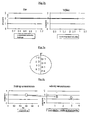
- Figure 1a and 1b represent an example of this correction, achieved on the local velocity measurements.
- Figure 1a shows the vertical repartition of the velocity sensors respectively located on positions 0, 1, 2, 3 in the well cross-section where the flow is stationary and figure 1b shows the correction of an erroneous measurements set.
- sensor 2 If sensor 1 and sensor 3 measure a positive (non zero) velocity value, then sensor 2 (located between sensors 1 and 3) should also measure a positive (non zero) value. If sensor 2 measures a negative or 0 value, then its measurement can be considered erroneous. A simple correction is to decide to ignore this measurement while conducting the following interpretation. Another solution is to set sensor 2 value as the average of both sensor 1 and sensor 3 values as represented on figure 1b.
- figure 1a represents a two-phase water/oil stationary flow and that 4 electrical probes are positioned along the vertical diameter of the well cross-section, said probes being located with a number from 0 to 3 from bottom to top. If sensor 0 shows 0 % water hold-up and probes 1 or 2 show strictly positive water hold-up, then at least one sensor measurement has to be declared erroneous because this set of measurements does not comply with basic physical principles. A simple correction is either to ignore this measurement or to give the measurement of sensor 0 the same value as the measurement of sensor 1 for instance.
- the corrections step may also comprise a check for mutual compliance of the data. Once the simplest measurement errors have been corrected, a more advanced check can be made. After having compared coherence of the measurements of the same type, one needs to check for their mutual coherence and correct them when identified. Typically, the local hold-up measurements will be compared with the local velocity measurements.
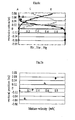
- Figures 2a and 2b represent an example of this correction.
- the velocity of water and the velocity of oil are - approximately - both uniform.
- the hold-up and velocity sensors are coupled: pairs of one hold-up sensor and one velocity sensor are co-located along the vertical diameter of the well cross-section, as showed on figure 2a where the velocity sensors, numbered 0 to 3, are on the left hand-side of the flow section and the water hold-up sensors, numbered 4 to 7, are located on the right hand-side of it.
- « o » refers to oil
- « w » refers to water
- « g » refers to gas.
- Vo and Vw are different. Let us take the case when the deviation is 89°. Then Vo is superior to Vw, due to known physical principles.
- the velocity measurements are the ones presented on figure 2b on the right hand-side diagram, then there is an obvious incoherence between the velocity measurements and the hold-up measurements showed on the left hand-side diagram.
- the hold-up 2 indicates that the oil/water interface is below its current position while the velocity sensor 6 tends to show that this interface is above said sensor. Then depending on the relative confidence towards measured velocity and measured hold-up, a correction on one of both (possibly both) data has to be implemented.
- a further correction aiming at refining the set of measurements.
- This correction is based on a closer analysis of the velocity measurements in order to inject the result of this analysis into the set of hold-up measurements via a fictive point that will precise this hold-up set. It is also possible to handle the reverse procedure and analyze the set of hold-up measurements in order to inject a fictive velocity measurement that will sharpen the result of the analysis of the velocity set.
- FIG. 3a An example of this refining correction can been seen on figures 3a and 3b.
- the flow pattern is supposed to be a two-phase stratified oil/water flow (stationary) and the velocity of water and the velocity of oil are approximately both uniform.
- the hold-up probes and the velocity sensors are not co-located along the vertical diameter of the well cross-section but are cross-positioned, hold-up sensors, numbered 0 to 3, being on the left hand-side of the well and velocity sensors, numbered 4 to 7, on the right hand-side.
- the set of hold-up measurements is used to improve the set of velocity measurements.
- the hold-up sensor 2 measures 60% of water volumetric fraction. This indicates that this sensor is positioned on the oil/water interface.
- the velocity sensors do not see this interface because they are either located in the oil or in the water. Consequently, from the hold-up measurements giving the position of the interface, it is possible to inject this information in the velocity measurements. This can be done by adding virtual velocity points just above and below the interface respectively close to the upper real measured point 6 and the lower real measured point 5.
- the hold-up sensors do not detect any gas because this latter flows on the very top of the well cross section. If the highest velocity sensor is above the highest hold-up sensor, this velocity sensor may detect an increased velocity. This feature will indicate the presence of gas while the non-corrected hold-up interpolation profile would have ignored this presence. Consequently, a virtual gas hold-up sensor can be added at the same position as the highest velocity sensor and its measured value can be set as it saw 100% of gas. (with 90° of deviation and for current flow velocities, it is reasonable to have a stratified flow).
- corrections step may comprise one, several or all of these correction procedures.
- these corrections may be indifferently achieved each one after the other, in any order, or it is also possible to include between one of them the selection of the flow model that will permit to interpolate these sets of measurements.
- the flow model is a combination of predetermined hold-up profile and velocity profile that correspond to a known flow pattern.
- Different flow models have been created in order to describe any type of flow that can be encountered in a well. Examples of flow models are known:
- the Poiseuille model represented in Figure 8, is the classical one to represent a laminar mono-phase flow in a cylindrical vertical pipe. This model fits a mono-dimension binomial function of the radius to the velocity measurements. Hold-up measurements are irrelevant. However, this model will not be used in many cases concerning a well effluent because velocities are typically too high for the flow to remain laminar, and the flow is turbulent in most cases.
- V o and V w represent respectively the velocity of oil and the velocity of water across a section S of a cylindrical pipe.
- H w and Ho represent respectively the volumetric fraction of water and the volumetric fraction of oil in the measured cross-section.
- S w and S o respectively represent the surface of pipe that is covered with oil in the cross-section and the surface of pipe that is covered with water in said cross-section.
- the choice of the flow model may be either made by a person who is in charge of running the method of the invention or by an automatic decision chain.
- a "manual" decision it is the person that is supervising the method of the invention who is going to select a given flow model according to his own knowledge of the effluent flow, the well deviation...
- the process will check several predetermined criteria in order to decide which flow model will be used. For example, it will check whether the flow is an oil/water flow or not: if the electrical probes detect oil and water and the optical probes detect no gas, the flow is a bi-phase oil/water flow.
- the process will check whether the flow is stratified or not: if the deviation is close to horizontal and measured velocities are all below a maximum value (e.g. 2m/s in a pipe having a diameter of 15.24 cm (6 inches)), the flow might be stratified.
- a maximum value e.g. 2m/s in a pipe having a diameter of 15.24 cm (6 inches)
- Another criterion to apply a stratified flow model may be a deviation close to horizontal and all probes except one measuring a water hold-up of 1 or 0.
- the automatic process recognizes an oil/water stratified flow, it will apply, for example, the flow model disclosed in the patent EP0519809.
- the step of defining the flow model can be achieved before any correction of the measurements, between two corrections or after the complete corrections step has been achieved.
- the flow model has been selected prior to any correction or if other corrections have been done on the measurements after the selection of said flow model, it might be useful to check whether the flow model is still suitable.
- this model is changed it might be useful to check whether all the corrections that have been made are still coherent.
- corrections step and selection of the flow model will be achieved, in a kind of iterative way, until the volumetric fraction measurements and the velocity measurements fit the last selected flow model.
- the local velocity and volumetric fraction measurements will be interpolated. Actually, these measurements do not necessarily correspond perfectly to the input needed for the selected flow model. Consequently, a transition step is needed to convert these local measurements into an "inputable" format. This can be done by a simple unit conversion but it can also be a change in the physical nature of the data. For example, in a bi-phase liquid/gas flow occurring in a deviated well, the local velocity measurements represent the velocity of the mixture. Thus, it is neither the velocity of the fluid, nor the velocity of the gas.
- the interpolation step may apply on the local mixture velocity, from which the liquid velocity profile and the gas velocity profile will be deduced afterwards.
- the interpolation step is achieved on both the velocity measurements and the hold-up measurements according to the selected flow model.
- the example represented on figure 4 shows the result of an interpolation step, using a flow model based on the least squares method, achieved on four local water hold-up measurements acquired in a pipe having a diameter of 20.32 cm (8 inches).
- the result of the interpolation step will give a set of profiles.
- these profiles will be a water volumetric fraction (hold-up), an oil volumetric fraction, a gas volumetric fraction, a water velocity, an oil velocity and a gas velocity profile.
- the latest step of the method of the invention is the calculation of the relative volumetric flow rates of the phases by integration of said volumetric fraction and/or velocity profiles over said section of the well at the depth where the local measurements have been acquired.
- the method of the invention thus permits to calculate the relative volumetric flow-rates of each phase of the effluent from local volumetric fraction and velocity measurements that have been acquired in the well, at a given depth. Re-applying this method at any depth of the well where local measurements have been acquired will give a view of the flow characteristics of the effluent. It will then be possible to manage the production of said well by focusing on certain zones and reducing the production of some others.
- Figure 5 is a schematic diagram of an example of flowchart implementing the method of the invention.
- the boxes represent the different steps of the method of the invention. It can be seen in this example of the method of the invention that a correction of systematic errors is made prior to the selection of the flow model. Moreover, the corrections that have been achieved after the selection of the flow model may lead to a new selection of said model, as said before.
- the flow conditions of a tri-phase effluent are known and are such that: the pipe internal diameter is 6 inches, the deviation of the pipe is of 88°, the water volumetric flow rate is 10 m 3 /h, the oil volumetric flow rate is 10 m 3 /h and the gas volumetric flow rate is 6.9 m 3 /h.
- the flow conditions are made stationary and stable. Nonetheless, the flow regime is non-stationary in such conditions: long bubbles of gas flow on top of a partly segregated oil/water stream.
- the measurement device bears five velocity sensors (mini-spinners) spread at known positions along the vertical diameter of the pipe. In the same manner, six optical probes and six electrical probes respectively measure the water hold-up and the gas hold-up across the pipe.
- the data used for this example are the ones measured with the above sensors averaged over a period of time close to 1 minute, plus some miscellaneous parameters (rheology of the fluids, sensors positions, ).
- Figure 6a represents hold-up values ⁇ that have been measured by the six electrical probes and holdup values ⁇ that have been acquired with the optical probes.
- Figure 6b represents the interpolated profiles that have been acquired through the method of the invention for both the water hold-up (curve A) and the gas hold-up (curve B).
- the flow model that has been chosen for implementing the method of the invention is the one based on the least squares method.
- Figure 6c additionally shows the oil hold-up profile (curve C) that has been obtained by simple subtraction of the two other profiles.
- Figures 7a represents the measured local velocities ⁇ of the mixture that are deduced from the rotational velocities of the five spinners (taking the calibration of these spinners into account).
- Figure 7b shows the curve corresponding to a gas velocity profile that has been deduced by using the interpolated gas hold-up profile and a gas/liquid slippage velocity obtained with a slippage model according to the method of the invention.
- Figure 7c additionally represents the oil and water velocity profiles, respectively (curves C and A), that have been defined using the liquid velocity profile (calculated with the interpolated oil and water hold-up profiles) and a slippage model and the oil/water slippage velocity in the method of the invention.
- the model of the invention thus leads to volumetric fraction and velocity profile for each phase of the effluent flowing in the well, said profile being as close as possible to the real flow conditions: actually, most of the factors that may distort the local measurements are carefully identified and corrected, while keeping all these measurements coherent with each other.
Landscapes
- Physics & Mathematics (AREA)
- Geology (AREA)
- Life Sciences & Earth Sciences (AREA)
- Engineering & Computer Science (AREA)
- Mining & Mineral Resources (AREA)
- Fluid Mechanics (AREA)
- General Life Sciences & Earth Sciences (AREA)
- Environmental & Geological Engineering (AREA)
- Geophysics (AREA)
- Geochemistry & Mineralogy (AREA)
- General Physics & Mathematics (AREA)
- Measuring Volume Flow (AREA)
- Indicating Or Recording The Presence, Absence, Or Direction Of Movement (AREA)
- Other Investigation Or Analysis Of Materials By Electrical Means (AREA)
- Organic Low-Molecular-Weight Compounds And Preparation Thereof (AREA)
- Investigating Or Analyzing Non-Biological Materials By The Use Of Chemical Means (AREA)
- Geophysics And Detection Of Objects (AREA)
- Aerodynamic Tests, Hydrodynamic Tests, Wind Tunnels, And Water Tanks (AREA)
Claims (12)
- Verfahren zum Berechnen der relativen Volumendurchflüsse wenigstens einer der Phasen eines in einem Bohrloch fließenden mehrphasigen Ausflusses, wobei das Verfahren einen ersten Schritt des Erfassens lokaler Volumenanteile und/oder lokaler Geschwindigkeiten der Phasen über einen Querschnitt des Bohrlochs bei einer bestimmten Tiefe umfasst, dadurch gekennzeichnet, dass das Verfahren ferner umfasst:- Korrigieren der Messungen des lokalen Volumenanteils und/oder der lokalen Geschwindigkeit, um sie aneinander und/oder an die Ausflussströmungsbedingungen anzupassen;- Auswählen eines geeigneten Strömungsmodells, das die Ausflussströmung mathematisch repräsentiert;- Interpolieren der Messungen der lokalen Volumenanteile und/oder der lokalen Geschwindigkeit durch das ausgewählte Strömungsmodell, um ein Volumenanteilprofil und/oder ein Geschwindigkeitsprofil für wenigstens eine Phase des Ausflusses über den Querschnitt des Bohrlochs bei der Tiefe zu erhalten; und- Berechnen der relativen Volumendurchflüsse der wenigstens einen Phase durch Integrieren des Volumenanteil- und/oder des Geschwindigkeitsprofils über den Querschnitt des Bohrlochs bei der Tiefe.
- Verfahren nach Anspruch 1, bei dem der Korrekturschritt das Korrigieren der systematischen Messfehler, die durch die Messmittel bedingt sind, umfasst.
- Verfahren nach Anspruch 1 oder 2, bei dem der Korrekturschritt das Prüfen der Kohärenz der Messungen der lokalen Volumenanteile untereinander und/oder der Kohärenz der Messungen der lokalen Geschwindigkeiten untereinander umfasst.
- Verfahren nach einem der Ansprüche 1 bis 3, bei dem der Korrekturschritt das Prüfen der gegenseitigen Kohärenz der Messungen der lokalen Volumenanteile und der Messungen der lokalen Geschwindigkeiten umfasst.
- Verfahren nach einem vorhergehenden Anspruch, bei dem der Korrekturschritt das Verfeinern der Messungen der lokalen Volumenanteile und der Messungen der lokalen Geschwindigkeiten anhand des Ergebnisses der Analyse der Messungen der lokalen Geschwindigkeiten bzw. der Messungen der lokalen Volumenanteile umfasst.
- Verfahren nach einem vorhergehenden Anspruch, bei dem die Auswahl des geeigneten Strömungsmodells durch die Analyse der Gruppe von Messungen der Volumenanteile und/oder der Geschwindigkeiten automatisch erfolgt.
- Verfahren nach einem vorhergehenden Anspruch, das ferner die folgenden Schritte umfasst:- Messen der Geschwindigkeit des Kabels, mit dem die Mittel zum Messen der Volumenanteile und der Geschwindigkeiten im Bohrloch abgesenkt werden;- Bestimmen der geometrischen Charakteristik des Bohrlochs.
- Verfahren nach einem vorhergehenden Anspruch, das ferner das Bestimmen der relativen Richtung des Bohrlochs umfasst.
- Verfahren nach einem der vorhergehenden Ansprüche, bei dem die Auswahl des Strömungsmodells verifiziert wird, nachdem einige Korrekturen an den Messungen der lokalen Volumenanteile und der lokalen Geschwindigkeiten vorgenommen worden sind.
- Verfahren nach einem der vorhergehenden Ansprüche, bei dem die Schritte folgendermaßen ausgeführt werden:- Korrigieren der systematischen Messfehler, die durch die Messmittel bedingt sind;- Auswählen eines geeigneten Strömungsmodells;- Prüfen der Kohärenz der Messungen der lokalen Volumenanteile untereinander und/oder der Kohärenz der Messungen der lokalen Geschwindigkeiten untereinander;- Prüfen der Messungen der lokalen Volumenanteile und der Messungen der lokalen Geschwindigkeiten auf gegenseitige Kohärenz;- Verfeinern der Messungen der lokalen Volumenanteile und der Messungen der lokalen Geschwindigkeiten anhand des Ergebnisses der Analyse der Messungen der lokalen Geschwindigkeiten bzw. der Messungen der lokalen Volumenanteile;- erneutes Ausführen der obigen Schritte, bis die Messungen der lokalen Volumenanteile und/oder die Messungen der lokalen Geschwindigkeiten mit dem Strömungsmodell, das ausgewählt worden ist, übereinstimmen;- Interpolieren der Messungen der lokalen Volumenanteile und der Messungen der lokalen Geschwindigkeiten durch das ausgewählte Strömungsmodell, um ein Volumenanteil- und/oder ein Geschwindigkeitsprofil für wenigstens eine Phase des Ausflusses über den Querschnitt des Bohrlochs bei der Tiefe zu erhalten;- Berechnen der relativen Volumendurchflüsse der wenigstens einen Phase durch Integrieren des Volumenanteilprofils und/oder des Geschwindigkeitsprofils über den Querschnitt des Bohrlochs bei der Tiefe.
- Verfahren nach einem der vorhergehenden Ansprüche, bei dem die Messungen der lokalen Volumenanteile der Wasser-Volumenanteil und/oder der Gas-Volumenanteil in dem Bohrlochausfluss sind, während der Öl-Volumenanteil in dem Ausfluss aus den vorstehenden Anteilen abgeleitet wird.
- Verfahren nach einem der vorhergehenden Ansprüche, bei dem die Messungen der lokalen Geschwindigkeit durch eine Gruppe von Schleudereinrichtungen erfasst werden.
Applications Claiming Priority (3)
| Application Number | Priority Date | Filing Date | Title |
|---|---|---|---|
| GB0220389A GB2392731B (en) | 2002-09-03 | 2002-09-03 | Method for interpreting data measured in a hydrocarbon well in production |
| GB0220389 | 2002-09-03 | ||
| PCT/EP2003/050606 WO2004061268A1 (en) | 2002-09-03 | 2003-09-02 | Method for interpreting data measured in a hydrocarbon well in production |
Publications (2)
| Publication Number | Publication Date |
|---|---|
| EP1552108A1 EP1552108A1 (de) | 2005-07-13 |
| EP1552108B1 true EP1552108B1 (de) | 2006-06-21 |
Family
ID=9943369
Family Applications (1)
| Application Number | Title | Priority Date | Filing Date |
|---|---|---|---|
| EP03812072A Expired - Lifetime EP1552108B1 (de) | 2002-09-03 | 2003-09-02 | Verfahren zum auswerten von in einem kohlenwasserstoffbohrloch während der produktion gemessenen daten |
Country Status (12)
| Country | Link |
|---|---|
| US (1) | US7099780B2 (de) |
| EP (1) | EP1552108B1 (de) |
| CN (1) | CN1678815B (de) |
| AT (1) | ATE331119T1 (de) |
| AU (1) | AU2003302748A1 (de) |
| CA (1) | CA2497150C (de) |
| DE (1) | DE60306405T2 (de) |
| GB (1) | GB2392731B (de) |
| MX (1) | MXPA05001620A (de) |
| NO (1) | NO336408B1 (de) |
| RU (1) | RU2346155C2 (de) |
| WO (1) | WO2004061268A1 (de) |
Families Citing this family (14)
| Publication number | Priority date | Publication date | Assignee | Title |
|---|---|---|---|---|
| US7950464B2 (en) * | 2006-01-31 | 2011-05-31 | Production Control Services, Inc. | Multi-well controller |
| US7603236B2 (en) * | 2006-08-21 | 2009-10-13 | Schlumberger Technology Corporation | Method to determine fluid phase distribution and quantify holdup in a wellbore |
| NO327020B1 (no) * | 2006-08-28 | 2009-04-06 | Norsk Hydro As | Metode for beregning av grenseskiktniva |
| US7963326B2 (en) * | 2006-12-18 | 2011-06-21 | Production Control Services, Inc. | Method and apparatus for utilizing pressure signature in conjunction with fall time as indicator in oil and gas wells |
| CN101560879B (zh) * | 2008-04-15 | 2013-06-19 | 中国石油大学(北京) | 用于低渗透气藏的试井分析控制系统及方法 |
| US20120160011A1 (en) | 2010-12-23 | 2012-06-28 | Andrew Colin Whittaker | Apparatus and Method for Generating Steam Quality Delivered to A Reservoir |
| US20120251335A1 (en) * | 2011-04-01 | 2012-10-04 | Gregg Hurst | Pump controller with multiphase measurement |
| US9453407B2 (en) | 2012-09-28 | 2016-09-27 | Rosemount Inc. | Detection of position of a plunger in a well |
| NO335021B1 (no) * | 2012-11-27 | 2014-08-25 | Sinvent As | Fremgangsmåte for simulering av flerfasefase fluidstrømninger i rørledninger |
| US9534491B2 (en) | 2013-09-27 | 2017-01-03 | Rosemount Inc. | Detection of position of a plunger in a well |
| CN104989377B (zh) * | 2015-08-06 | 2020-09-25 | 北京航空航天大学 | 一种基于总流量与电导探针阵列信号的垂直井含水率测量方法 |
| CN107219564B (zh) * | 2017-05-17 | 2019-08-06 | 中国石油天然气股份有限公司 | 一种处理垂向连井剖面的方法及装置 |
| CN114169155B (zh) * | 2021-11-25 | 2023-07-14 | 北京美科华仪科技有限公司 | 一种依托剖面流速率定代表线的方法 |
| CN114645704B (zh) * | 2022-03-15 | 2024-07-16 | 山东工商学院 | 油相流量的测量方法及装置、设备、存储介质和测井仪 |
Family Cites Families (15)
| Publication number | Priority date | Publication date | Assignee | Title |
|---|---|---|---|---|
| FR2101037B1 (de) * | 1970-08-12 | 1973-04-27 | Schlumberger Prospection | |
| US4441362A (en) * | 1982-04-19 | 1984-04-10 | Dresser Industries, Inc. | Method for determining volumetric fractions and flow rates of individual phases within a multi-phase flow regime |
| SU1649277A1 (ru) * | 1987-12-21 | 1991-05-15 | Научно-Производственное Объединение "Нефтеавтоматика" | Устройство дл определени средних объемных расходов жидкости и газа газожидкостного потока в трубопроводе. |
| FR2637089B1 (fr) * | 1988-09-29 | 1990-11-30 | Schlumberger Prospection | Procede et dispositif pour l'analyse d'un ecoulement a plusieurs phases dans un puits d'hydrocarbures |
| US5586027A (en) * | 1989-06-12 | 1996-12-17 | Western Atlas International, Inc. | Method and apparatus for determining flow rates in multi-phase fluid flow mixtures |
| JP2816758B2 (ja) * | 1990-09-07 | 1998-10-27 | 株式会社日立製作所 | ファジイ推論を用いた流量測定装置及び方法 |
| FR2678022B1 (fr) * | 1991-06-18 | 1993-11-26 | Schlumberger Services Petroliers | Procede d'analyse d'un ecoulement diphasique dans un puits d'hydrocarbures. |
| RU2008617C1 (ru) * | 1991-06-25 | 1994-02-28 | Институт проблем управления РАН | Способ измерения покомпонентного расхода трехкомпонентного газожидкостного потока, проходящего по трубопроводу, и устройство для его осуществления |
| RU2087906C1 (ru) * | 1995-01-10 | 1997-08-20 | Виталий Георгиевич Беляков | Способ определения долевого содержания компонентов анализируемой среды и устройство для его осуществления |
| FR2732068B1 (fr) * | 1995-03-23 | 1997-06-06 | Schlumberger Services Petrol | Procede et dispositif pour la mesure locale de parametres d'ecoulement d'un fluide multiphasique et application dudit procede |
| US5561245A (en) * | 1995-04-17 | 1996-10-01 | Western Atlas International, Inc. | Method for determining flow regime in multiphase fluid flow in a wellbore |
| US5633470A (en) * | 1995-11-07 | 1997-05-27 | Western Atlas International, Inc. | Velocity and holdup determination method for stratified gas-liquid flow in highly inclined conduits |
| RU2097554C1 (ru) * | 1996-04-09 | 1997-11-27 | Государственная академия нефти и газа им.И.М.Губкина | Способ определения фазовых дебитов в нефтяной скважине |
| FR2797295B1 (fr) * | 1999-08-05 | 2001-11-23 | Schlumberger Services Petrol | Procede et appareil d'acquisition de donnees, dans un puits d'hydrocarbure en production |
| US6305216B1 (en) * | 1999-12-21 | 2001-10-23 | Production Testing Services | Method and apparatus for predicting the fluid characteristics in a well hole |
-
2002
- 2002-09-03 GB GB0220389A patent/GB2392731B/en not_active Expired - Fee Related
-
2003
- 2003-09-02 DE DE60306405T patent/DE60306405T2/de not_active Expired - Lifetime
- 2003-09-02 MX MXPA05001620A patent/MXPA05001620A/es active IP Right Grant
- 2003-09-02 EP EP03812072A patent/EP1552108B1/de not_active Expired - Lifetime
- 2003-09-02 CN CN038204398A patent/CN1678815B/zh not_active Expired - Lifetime
- 2003-09-02 WO PCT/EP2003/050606 patent/WO2004061268A1/en not_active Ceased
- 2003-09-02 AT AT03812072T patent/ATE331119T1/de not_active IP Right Cessation
- 2003-09-02 RU RU2005109415/03A patent/RU2346155C2/ru active
- 2003-09-02 CA CA2497150A patent/CA2497150C/en not_active Expired - Lifetime
- 2003-09-02 AU AU2003302748A patent/AU2003302748A1/en not_active Abandoned
-
2004
- 2004-07-22 US US10/523,886 patent/US7099780B2/en not_active Expired - Lifetime
-
2005
- 2005-04-01 NO NO20051636A patent/NO336408B1/no not_active IP Right Cessation
Also Published As
| Publication number | Publication date |
|---|---|
| CA2497150C (en) | 2012-01-10 |
| NO336408B1 (no) | 2015-08-17 |
| GB2392731B (en) | 2005-03-30 |
| GB2392731A (en) | 2004-03-10 |
| EP1552108A1 (de) | 2005-07-13 |
| AU2003302748A1 (en) | 2004-07-29 |
| MXPA05001620A (es) | 2005-04-25 |
| ATE331119T1 (de) | 2006-07-15 |
| RU2005109415A (ru) | 2005-09-10 |
| CN1678815A (zh) | 2005-10-05 |
| WO2004061268A1 (en) | 2004-07-22 |
| US7099780B2 (en) | 2006-08-29 |
| NO20051636L (no) | 2005-04-01 |
| RU2346155C2 (ru) | 2009-02-10 |
| DE60306405T2 (de) | 2007-07-05 |
| CA2497150A1 (en) | 2004-07-22 |
| GB0220389D0 (en) | 2002-10-09 |
| US20060041382A1 (en) | 2006-02-23 |
| DE60306405D1 (de) | 2006-08-03 |
| CN1678815B (zh) | 2013-07-10 |
Similar Documents
| Publication | Publication Date | Title |
|---|---|---|
| EP1552108B1 (de) | Verfahren zum auswerten von in einem kohlenwasserstoffbohrloch während der produktion gemessenen daten | |
| US5561245A (en) | Method for determining flow regime in multiphase fluid flow in a wellbore | |
| RU2754656C1 (ru) | Способ и система измерения расходов многофазного и/или многокомпонентного флюида, добываемого из нефтегазовой скважины | |
| US20120166157A1 (en) | Methods and Systems for Interpreting Multiphase Fluid Flow in A Conduit | |
| EP3181809A1 (de) | Verfahren zur erkennung von zunahme oder verlust einer bohrflüssigkeit in einer bohreinrichtung, zugehöriges berechnungssystem und zugehörige bohreinrichtung | |
| CN103376138B (zh) | 地下水监测井中垂直流量测定装置及其流速仪和探测方法 | |
| GB2441201A (en) | A method of determining fluid phase distribution and quantify holdup in a wellbore | |
| CN115992688B (zh) | 一种水平井油水两相界面混杂分层流时的持水率成像方法 | |
| WO2006132546A1 (en) | Method and apparatus for measuring nonhomogeneous flow phase velocities | |
| CN101512304A (zh) | 流体界面水平面的计算方法 | |
| US7674624B2 (en) | Method for real-time determination of volume fractions of a production fluid in a hydrocarbon reservoir | |
| Podio et al. | Integrated well performance and analysis | |
| WO1994025732A1 (en) | A method of determining the production rate of each of the phases in a well stream | |
| Zhang et al. | Early detection of the wear of coriolis flowmeters through in situ stiffness diagnosis | |
| US6532829B1 (en) | Fluid flow measurement | |
| US7726185B2 (en) | System and method for measuring flow in a pipeline | |
| Wu et al. | Oil-water flowrate measurement with sensing data and equidistant area-weighted average method | |
| JP5391021B2 (ja) | 高炉のテラス長さの測定方法、及び高炉のテラス長さの測定装置 | |
| Kouba et al. | A nonintrusive flowmetering method for two-phase intermittent flow in horizontal pipes | |
| Ye et al. | Study on the water holdup calculation and fluid distribution inversion methods for gas-water intermittent flow in inclined wells | |
| CN111380582A (zh) | 一种地质钻探水文测井装置及方法 | |
| Hacini et al. | A Fast Calibration Procedure to Assess the Reliability of Heat Pulse Flow Meter Measurements | |
| Bukhari et al. | Nonconstricting rectangular channels for measuring farm water deliveries | |
| Oden | An Automated Transmissivity Modeling Method for Use with Borehole Flowmeter Data | |
| Karlsen et al. | Advanced on-line data treatment for a bench scale heat flow calorimeter |
Legal Events
| Date | Code | Title | Description |
|---|---|---|---|
| PUAI | Public reference made under article 153(3) epc to a published international application that has entered the european phase |
Free format text: ORIGINAL CODE: 0009012 |
|
| 17P | Request for examination filed |
Effective date: 20050201 |
|
| AK | Designated contracting states |
Kind code of ref document: A1 Designated state(s): AT BE BG CH CY CZ DE DK EE ES FI FR GB GR HU IE IT LI LU MC NL PT RO SE SI SK TR |
|
| AX | Request for extension of the european patent |
Extension state: AL LT LV MK |
|
| DAX | Request for extension of the european patent (deleted) | ||
| GRAP | Despatch of communication of intention to grant a patent |
Free format text: ORIGINAL CODE: EPIDOSNIGR1 |
|
| GRAS | Grant fee paid |
Free format text: ORIGINAL CODE: EPIDOSNIGR3 |
|
| GRAA | (expected) grant |
Free format text: ORIGINAL CODE: 0009210 |
|
| AK | Designated contracting states |
Kind code of ref document: B1 Designated state(s): AT BE BG CH CY CZ DE DK EE ES FI FR GB GR HU IE IT LI LU MC NL PT RO SE SI SK TR |
|
| PG25 | Lapsed in a contracting state [announced via postgrant information from national office to epo] |
Ref country code: RO Free format text: LAPSE BECAUSE OF FAILURE TO SUBMIT A TRANSLATION OF THE DESCRIPTION OR TO PAY THE FEE WITHIN THE PRESCRIBED TIME-LIMIT Effective date: 20060621 Ref country code: SK Free format text: LAPSE BECAUSE OF FAILURE TO SUBMIT A TRANSLATION OF THE DESCRIPTION OR TO PAY THE FEE WITHIN THE PRESCRIBED TIME-LIMIT Effective date: 20060621 Ref country code: LI Free format text: LAPSE BECAUSE OF FAILURE TO SUBMIT A TRANSLATION OF THE DESCRIPTION OR TO PAY THE FEE WITHIN THE PRESCRIBED TIME-LIMIT Effective date: 20060621 Ref country code: SI Free format text: LAPSE BECAUSE OF FAILURE TO SUBMIT A TRANSLATION OF THE DESCRIPTION OR TO PAY THE FEE WITHIN THE PRESCRIBED TIME-LIMIT Effective date: 20060621 Ref country code: CH Free format text: LAPSE BECAUSE OF FAILURE TO SUBMIT A TRANSLATION OF THE DESCRIPTION OR TO PAY THE FEE WITHIN THE PRESCRIBED TIME-LIMIT Effective date: 20060621 Ref country code: FI Free format text: LAPSE BECAUSE OF FAILURE TO SUBMIT A TRANSLATION OF THE DESCRIPTION OR TO PAY THE FEE WITHIN THE PRESCRIBED TIME-LIMIT Effective date: 20060621 Ref country code: BE Free format text: LAPSE BECAUSE OF FAILURE TO SUBMIT A TRANSLATION OF THE DESCRIPTION OR TO PAY THE FEE WITHIN THE PRESCRIBED TIME-LIMIT Effective date: 20060621 Ref country code: AT Free format text: LAPSE BECAUSE OF FAILURE TO SUBMIT A TRANSLATION OF THE DESCRIPTION OR TO PAY THE FEE WITHIN THE PRESCRIBED TIME-LIMIT Effective date: 20060621 Ref country code: CZ Free format text: LAPSE BECAUSE OF FAILURE TO SUBMIT A TRANSLATION OF THE DESCRIPTION OR TO PAY THE FEE WITHIN THE PRESCRIBED TIME-LIMIT Effective date: 20060621 |
|
| REG | Reference to a national code |
Ref country code: GB Ref legal event code: FG4D |
|
| REG | Reference to a national code |
Ref country code: CH Ref legal event code: EP |
|
| RAP2 | Party data changed (patent owner data changed or rights of a patent transferred) |
Owner name: SCHLUMBERGER OILFIELD ASSISTANCE LIMITED Owner name: PETROLEUM RESEARCH & DEVELOPMENT N,V. Owner name: SCHLUMBERGER TECHNOLOGY B.V. Owner name: SCHLUMBERGER HOLDINGS LIMITED Owner name: SERVICES PETROLIERS SCHLUMBERGER |
|
| REG | Reference to a national code |
Ref country code: IE Ref legal event code: FG4D |
|
| REF | Corresponds to: |
Ref document number: 60306405 Country of ref document: DE Date of ref document: 20060803 Kind code of ref document: P |
|
| NLT2 | Nl: modifications (of names), taken from the european patent patent bulletin |
Owner name: SCHLUMBERGER HOLDINGS LIMITED Effective date: 20060719 |
|
| PG25 | Lapsed in a contracting state [announced via postgrant information from national office to epo] |
Ref country code: IE Free format text: LAPSE BECAUSE OF NON-PAYMENT OF DUE FEES Effective date: 20060904 |
|
| PG25 | Lapsed in a contracting state [announced via postgrant information from national office to epo] |
Ref country code: DK Free format text: LAPSE BECAUSE OF FAILURE TO SUBMIT A TRANSLATION OF THE DESCRIPTION OR TO PAY THE FEE WITHIN THE PRESCRIBED TIME-LIMIT Effective date: 20060921 Ref country code: SE Free format text: LAPSE BECAUSE OF FAILURE TO SUBMIT A TRANSLATION OF THE DESCRIPTION OR TO PAY THE FEE WITHIN THE PRESCRIBED TIME-LIMIT Effective date: 20060921 |
|
| PG25 | Lapsed in a contracting state [announced via postgrant information from national office to epo] |
Ref country code: MC Free format text: LAPSE BECAUSE OF NON-PAYMENT OF DUE FEES Effective date: 20060930 |
|
| PG25 | Lapsed in a contracting state [announced via postgrant information from national office to epo] |
Ref country code: ES Free format text: LAPSE BECAUSE OF FAILURE TO SUBMIT A TRANSLATION OF THE DESCRIPTION OR TO PAY THE FEE WITHIN THE PRESCRIBED TIME-LIMIT Effective date: 20061002 |
|
| PG25 | Lapsed in a contracting state [announced via postgrant information from national office to epo] |
Ref country code: PT Free format text: LAPSE BECAUSE OF FAILURE TO SUBMIT A TRANSLATION OF THE DESCRIPTION OR TO PAY THE FEE WITHIN THE PRESCRIBED TIME-LIMIT Effective date: 20061121 |
|
| REG | Reference to a national code |
Ref country code: CH Ref legal event code: PL |
|
| PLBE | No opposition filed within time limit |
Free format text: ORIGINAL CODE: 0009261 |
|
| STAA | Information on the status of an ep patent application or granted ep patent |
Free format text: STATUS: NO OPPOSITION FILED WITHIN TIME LIMIT |
|
| EN | Fr: translation not filed | ||
| 26N | No opposition filed |
Effective date: 20070322 |
|
| PG25 | Lapsed in a contracting state [announced via postgrant information from national office to epo] |
Ref country code: FR Free format text: LAPSE BECAUSE OF FAILURE TO SUBMIT A TRANSLATION OF THE DESCRIPTION OR TO PAY THE FEE WITHIN THE PRESCRIBED TIME-LIMIT Effective date: 20070504 Ref country code: GR Free format text: LAPSE BECAUSE OF FAILURE TO SUBMIT A TRANSLATION OF THE DESCRIPTION OR TO PAY THE FEE WITHIN THE PRESCRIBED TIME-LIMIT Effective date: 20060922 |
|
| PG25 | Lapsed in a contracting state [announced via postgrant information from national office to epo] |
Ref country code: BG Free format text: LAPSE BECAUSE OF FAILURE TO SUBMIT A TRANSLATION OF THE DESCRIPTION OR TO PAY THE FEE WITHIN THE PRESCRIBED TIME-LIMIT Effective date: 20060921 Ref country code: EE Free format text: LAPSE BECAUSE OF FAILURE TO SUBMIT A TRANSLATION OF THE DESCRIPTION OR TO PAY THE FEE WITHIN THE PRESCRIBED TIME-LIMIT Effective date: 20060621 |
|
| PG25 | Lapsed in a contracting state [announced via postgrant information from national office to epo] |
Ref country code: TR Free format text: LAPSE BECAUSE OF FAILURE TO SUBMIT A TRANSLATION OF THE DESCRIPTION OR TO PAY THE FEE WITHIN THE PRESCRIBED TIME-LIMIT Effective date: 20060621 Ref country code: LU Free format text: LAPSE BECAUSE OF NON-PAYMENT OF DUE FEES Effective date: 20060902 Ref country code: HU Free format text: LAPSE BECAUSE OF FAILURE TO SUBMIT A TRANSLATION OF THE DESCRIPTION OR TO PAY THE FEE WITHIN THE PRESCRIBED TIME-LIMIT Effective date: 20061222 |
|
| PG25 | Lapsed in a contracting state [announced via postgrant information from national office to epo] |
Ref country code: FR Free format text: LAPSE BECAUSE OF FAILURE TO SUBMIT A TRANSLATION OF THE DESCRIPTION OR TO PAY THE FEE WITHIN THE PRESCRIBED TIME-LIMIT Effective date: 20060621 Ref country code: CY Free format text: LAPSE BECAUSE OF FAILURE TO SUBMIT A TRANSLATION OF THE DESCRIPTION OR TO PAY THE FEE WITHIN THE PRESCRIBED TIME-LIMIT Effective date: 20060621 |
|
| PGFP | Annual fee paid to national office [announced via postgrant information from national office to epo] |
Ref country code: IT Payment date: 20170922 Year of fee payment: 15 |
|
| PGFP | Annual fee paid to national office [announced via postgrant information from national office to epo] |
Ref country code: NL Payment date: 20170925 Year of fee payment: 15 |
|
| PGFP | Annual fee paid to national office [announced via postgrant information from national office to epo] |
Ref country code: DE Payment date: 20171130 Year of fee payment: 15 |
|
| REG | Reference to a national code |
Ref country code: DE Ref legal event code: R119 Ref document number: 60306405 Country of ref document: DE |
|
| REG | Reference to a national code |
Ref country code: NL Ref legal event code: MM Effective date: 20181001 |
|
| PG25 | Lapsed in a contracting state [announced via postgrant information from national office to epo] |
Ref country code: NL Free format text: LAPSE BECAUSE OF NON-PAYMENT OF DUE FEES Effective date: 20181001 |
|
| PG25 | Lapsed in a contracting state [announced via postgrant information from national office to epo] |
Ref country code: IT Free format text: LAPSE BECAUSE OF NON-PAYMENT OF DUE FEES Effective date: 20180902 Ref country code: DE Free format text: LAPSE BECAUSE OF NON-PAYMENT OF DUE FEES Effective date: 20190402 |
|
| PGFP | Annual fee paid to national office [announced via postgrant information from national office to epo] |
Ref country code: GB Payment date: 20220714 Year of fee payment: 20 |
|
| REG | Reference to a national code |
Ref country code: GB Ref legal event code: PE20 Expiry date: 20230901 |
|
| PG25 | Lapsed in a contracting state [announced via postgrant information from national office to epo] |
Ref country code: GB Free format text: LAPSE BECAUSE OF EXPIRATION OF PROTECTION Effective date: 20230901 |