EP1551033B1 - Nuclear fuel assembly debris filter bottom nozzle - Google Patents
Nuclear fuel assembly debris filter bottom nozzle Download PDFInfo
- Publication number
- EP1551033B1 EP1551033B1 EP04030857A EP04030857A EP1551033B1 EP 1551033 B1 EP1551033 B1 EP 1551033B1 EP 04030857 A EP04030857 A EP 04030857A EP 04030857 A EP04030857 A EP 04030857A EP 1551033 B1 EP1551033 B1 EP 1551033B1
- Authority
- EP
- European Patent Office
- Prior art keywords
- chamfer
- flow
- holes
- fuel assembly
- plate
- Prior art date
- Legal status (The legal status is an assumption and is not a legal conclusion. Google has not performed a legal analysis and makes no representation as to the accuracy of the status listed.)
- Active
Links
- 239000003758 nuclear fuel Substances 0.000 title claims description 14
- 239000000446 fuel Substances 0.000 claims description 65
- 239000002826 coolant Substances 0.000 claims description 24
- 239000012530 fluid Substances 0.000 claims description 6
- 230000004323 axial length Effects 0.000 claims 1
- 230000001939 inductive effect Effects 0.000 claims 1
- 238000013461 design Methods 0.000 description 17
- 230000009467 reduction Effects 0.000 description 8
- 238000000034 method Methods 0.000 description 6
- 238000013459 approach Methods 0.000 description 5
- 238000004519 manufacturing process Methods 0.000 description 4
- 239000008188 pellet Substances 0.000 description 4
- 230000002829 reductive effect Effects 0.000 description 4
- 230000000712 assembly Effects 0.000 description 3
- 238000000429 assembly Methods 0.000 description 3
- 210000004027 cell Anatomy 0.000 description 3
- 238000001914 filtration Methods 0.000 description 3
- 230000000670 limiting effect Effects 0.000 description 3
- 239000007788 liquid Substances 0.000 description 3
- 230000007246 mechanism Effects 0.000 description 3
- 230000008569 process Effects 0.000 description 3
- XLYOFNOQVPJJNP-UHFFFAOYSA-N water Substances O XLYOFNOQVPJJNP-UHFFFAOYSA-N 0.000 description 3
- 230000001010 compromised effect Effects 0.000 description 2
- 238000011161 development Methods 0.000 description 2
- 230000000694 effects Effects 0.000 description 2
- 230000004992 fission Effects 0.000 description 2
- 230000006872 improvement Effects 0.000 description 2
- 230000001681 protective effect Effects 0.000 description 2
- 230000008439 repair process Effects 0.000 description 2
- 238000012360 testing method Methods 0.000 description 2
- ZOXJGFHDIHLPTG-UHFFFAOYSA-N Boron Chemical compound [B] ZOXJGFHDIHLPTG-UHFFFAOYSA-N 0.000 description 1
- 241000242541 Trematoda Species 0.000 description 1
- 230000002411 adverse Effects 0.000 description 1
- 229910052796 boron Inorganic materials 0.000 description 1
- 210000002421 cell wall Anatomy 0.000 description 1
- 238000005253 cladding Methods 0.000 description 1
- 238000007689 inspection Methods 0.000 description 1
- 238000009434 installation Methods 0.000 description 1
- 210000003041 ligament Anatomy 0.000 description 1
- 238000003754 machining Methods 0.000 description 1
- 239000000463 material Substances 0.000 description 1
- 239000002184 metal Substances 0.000 description 1
- 239000002923 metal particle Substances 0.000 description 1
- 238000012986 modification Methods 0.000 description 1
- 230000004048 modification Effects 0.000 description 1
- 230000000717 retained effect Effects 0.000 description 1
- 238000007514 turning Methods 0.000 description 1
- 238000003466 welding Methods 0.000 description 1
Images


Classifications
-
- G—PHYSICS
- G21—NUCLEAR PHYSICS; NUCLEAR ENGINEERING
- G21C—NUCLEAR REACTORS
- G21C3/00—Reactor fuel elements and their assemblies; Selection of substances for use as reactor fuel elements
- G21C3/30—Assemblies of a number of fuel elements in the form of a rigid unit
- G21C3/32—Bundles of parallel pin-, rod-, or tube-shaped fuel elements
- G21C3/3206—Means associated with the fuel bundle for filtering the coolant, e.g. nozzles, grids
-
- G—PHYSICS
- G21—NUCLEAR PHYSICS; NUCLEAR ENGINEERING
- G21C—NUCLEAR REACTORS
- G21C3/00—Reactor fuel elements and their assemblies; Selection of substances for use as reactor fuel elements
- G21C3/02—Fuel elements
- G21C3/04—Constructional details
-
- G—PHYSICS
- G21—NUCLEAR PHYSICS; NUCLEAR ENGINEERING
- G21C—NUCLEAR REACTORS
- G21C15/00—Cooling arrangements within the pressure vessel containing the core; Selection of specific coolants
- G21C15/02—Arrangements or disposition of passages in which heat is transferred to the coolant; Coolant flow control devices
- G21C15/04—Arrangements or disposition of passages in which heat is transferred to the coolant; Coolant flow control devices from fissile or breeder material
- G21C15/06—Arrangements or disposition of passages in which heat is transferred to the coolant; Coolant flow control devices from fissile or breeder material in fuel elements
-
- G—PHYSICS
- G21—NUCLEAR PHYSICS; NUCLEAR ENGINEERING
- G21C—NUCLEAR REACTORS
- G21C19/00—Arrangements for treating, for handling, or for facilitating the handling of, fuel or other materials which are used within the reactor, e.g. within its pressure vessel
- G21C19/28—Arrangements for introducing fluent material into the reactor core; Arrangements for removing fluent material from the reactor core
- G21C19/30—Arrangements for introducing fluent material into the reactor core; Arrangements for removing fluent material from the reactor core with continuous purification of circulating fluent material, e.g. by extraction of fission products deterioration or corrosion products, impurities, e.g. by cold traps
-
- Y—GENERAL TAGGING OF NEW TECHNOLOGICAL DEVELOPMENTS; GENERAL TAGGING OF CROSS-SECTIONAL TECHNOLOGIES SPANNING OVER SEVERAL SECTIONS OF THE IPC; TECHNICAL SUBJECTS COVERED BY FORMER USPC CROSS-REFERENCE ART COLLECTIONS [XRACs] AND DIGESTS
- Y02—TECHNOLOGIES OR APPLICATIONS FOR MITIGATION OR ADAPTATION AGAINST CLIMATE CHANGE
- Y02E—REDUCTION OF GREENHOUSE GAS [GHG] EMISSIONS, RELATED TO ENERGY GENERATION, TRANSMISSION OR DISTRIBUTION
- Y02E30/00—Energy generation of nuclear origin
- Y02E30/30—Nuclear fission reactors
Definitions
- the present invention relates generally to nuclear reactors and, more particularly, is concerned with a debris filter bottom nozzle for a nuclear fuel assembly.
- the present invention provides a debris filter bottom nozzle in a fuel assembly designed to satisfy the aforementioned needs.
- the bottom nozzle of the present invention includes a nozzle plate employing the concept of having flow holes smaller in diameter than have been otherwise used prior to that disclosed in U.S. Patent No. 4,900,507 , with a further improved reduction in pressure drop across the nozzle plate.
- the flow holes are preferably about 0,48 cm (0.190 inch) in diameter at their narrowest constriction, which makes them sized to filter out debris which otherwise collects primarily in the sections between the bottom nozzle and the lowermost grid and in the unoccupied spaces of the lowermost grid and causes fuel rod fretting failures.
- This invention provides a venturi contour to the flow holes to further reduce the pressure drop across the bottom nozzle plate.
- the inlet through the flowthrough hole is provided with a double chamfer, with the angles between the double chamfer optimized to provide the lowest pressure drop.
- the double chamfer approximates a radius, i.e., a curve, without the attendant expense and difficulties of machining a curved surface, which streamlines the flow through the holes.
- the present invention is directed to a debris filter bottom nozzle useful in a fuel assembly for a nuclear reactor wherein the fuel assembly includes a plurality of nuclear fuel rods, at least a lowermost grid supporting the fuel rods in an organized array and having unoccupied spaces defined therein allowing flow of fluid coolant therethrough.
- the debris filter bottom nozzle is disposed adjacent to and below the grid and below lower ends of the fuel rods.
- the bottom nozzle comprises a nozzle plate fixed on support means facing towards a lowermost grid and having defined therethrough a plurality of flow apertures individually sized so that most debris larger in size than the maximum dimension of the unoccupied spaces through the lowermost grid are captured below, within or proximate the aperture outlet orifice.
- the fuel assembly 10 is the type used in a pressurized water reactor and has a structural skeleton which, at its lower end, includes the debris filter bottom nozzle 12 of the present invention (which will be described later in detail).
- the bottom nozzle 12 supports the fuel assembly 10 on a lower core support plate 14 in the core region of the nuclear reactor (not shown).
- the structural skeleton of the fuel assembly 10 also includes a top nozzle 16 at its upper end and a number of guide tubes or thimbles 18, which extend longitudinally between the bottom and top nozzles 12 and 16 and at opposite ends are rigidly attached thereto.
- the fuel assembly 10 further includes a plurality of traverse grids 20 axially-spaced along, and mounted to, the grid thimble tubes 18 and an organized array of elongated fuel rods 22 traversely-spaced and supported by the grids 20. Also, the assembly 10 has an instrumentation tube 24 located in the center thereof and extending between, and mounted to, the bottom and top nozzles 12 and 16. With such an arrangement of parts, fuel assembly 10 forms an integral unit capable of being conveniently handled without damaging the assembly parts.
- each fuel rod 22 in the array thereof in the assembly 10 is held in spaced relationship with one another by the grids 20 spaced along the fuel assembly length.
- Each fuel rod 22 includes nuclear fuel pellets 26 and is closed at its opposite ends by upper and lower end plugs 28 and 30.
- the pellets 26 are maintained in a stack by a plenum spring 32 disposed between the upper end plug 28 and the top of the pellet stack.
- the fuel pellets 26, composed of fissile material, are responsible for creating the reactive power of the reactor.
- a liquid moderator/coolant such as water or water containing boron, is pumped upwardly through a plurality of flow openings in the lower core plate 14 to the fuel assembly.
- the bottom nozzle 12 of the fuel assembly 10 passes the coolant upwardly through the guide tubes 18 and along the fuel rods 22 of the assembly in order to extract heat generated therein for the production of useful work.
- a number of control rods 34 are reciprocally moveable in the guide thimbles 18 located at predetermined positions in the fuel assembly 10.
- a rod cluster control mechanism 36 positioned above the top nozzle 16 supports the control rods 34.
- the control mechanism has an internally threaded cylindrical member 37 with a plurality of radially-extending flukes or arms 38. Each arm 38 is interconnected to control rod 34 such that the control rod mechanism 36 is operable to move the control rods vertically in the guide thimbles 18 to thereby control the fission process in the fuel assembly 10, all in a well known manner.
- the present invention relates to a bottom nozzle 12 which, in addition to supporting the fuel assembly 10 on the lower core plate 14, also contains features which function to filter out potentially damaging size debris from the coolant flow passed upwardly through the bottom nozzle with a a reduction in pressure drop over that experienced in the design of the '507 patent.
- the bottom nozzle 12 includes support means, for example the skirt 40 shown in Figure 2 .
- the support means, skirt 40 in this embodiment includes a plurality of corner legs 42 for supporting the fuel assembly 10 on the lower core plate 14.
- a generally rectangular planar plate 46 is suitably attached, such as by welding, to the upper surface 44 of the support skirt 40.
- the debris filter bottom nozzle 12 of this invention is very similar to that described in U.S. Patent No. 4,900,507 , assigned to the assignee of this invention.
- the flow holes 58 included inlet chamfers at each flow hole.
- the flow holes 48 of the '507 patent were preferably uniform in cross-sectional size and defined a pattern which substantially covers every portion of the plate 46 across its length and breadth.
- the diameter of the flow holes 48 does not allow passage of most of the debris that is of a size typically caught in the lowermost support grid 20. If the debris is small enough to pass through these plate flow holes 48, it will in most cases also pass through the grids 20 since the diameter of the flow holes 48 is small enough to catch most of the debris having a cross section larger than that of the unoccupied spaces through a cell of the support grid 20.
- Such unoccupied spaces are typically found in adjacent corners formed by the interleaved straps composing the grid 20 and are bounded by the corners, respective dimples and spring formed on the grip straps and the fuel rods 22, which extend through the grid cells.
- the debris filter bottom nozzle 12 of the present invention thereby significantly reduces the potential for debris-induced fuel rod failures. It should be appreciated that the improvement of this invention does not require that the narrowest cross section of the flow through holes 48 in the nozzle plate 46 be equal or smaller than the largest cross sectional dimension of the unoccupied spaces through a cell of the support grid 20, especially when the outlet of the flow through holes 48 effectively operate in conjunction with adjoining structures to further constrict the flow path.
- the grid straps further delimit the flow and trap debris in the area between the protective grid and the nozzle plate.
- a nominal diameter for the flow holes 48 of about 0,48 cm (0.190 inch) was selected, with 0.48 +/- 0.02 cm (0190 +/- 0.008 inch) being preferred). It is possible for the holes 48 to be made somewhat smaller in diameter. All observed primary debris-induced fuel rod failures were at or below the lowermost grid and appear to be caused by debris somewhat larger than 0,48 cm (0.190 inch) in width. Other smaller debris typically present in the reactor coolant systems is believed to be relatively delicate in nature and not likely to cause rod damage since little or no significant damage can be observed above the lowermost grid. The evidence suggests that, heretofore, the damaging size debris is effectively stopped by the lowermost grid 20.
- the debris filter bottom nozzle 12 with approximately 0,48 cm (0.190 inch) diameter sized flow holes 48 defined in the bottom nozzle plate 46, is expected to reduce by 90% the potential rod damaging metallic debris carried into fuel assemblies by the primary coolant flow. Such estimate may be conservative since it appears likely that debris substantially larger than 0,48 cm (0,190 inch) in width may do a disproportionate amount of fuel rod damage.
- the plate 46 includes one central instrumentation tube hole 50 and a number of guide thimble holes 52.
- the flow holes 48 described in the '507 patent included a long taper inlet chamfer, about 0,36 cm (0.140 inch) in length and forming an angle of approximately 15° +/- 3° to the axis of the hole 48.
- the chamfer on the inlet was employed on each of the flow holes 48 to optimize the flow, i.e., minimize the loss coefficient increase due to the higher frictional affect inherent with the smaller flow holes 48.
- the longer chamfer 50 was thought to prevent the flow stream from reattaching within the adapter plate holes 48 and increasing pressure drop across the fuel assembly 10.
- the debris filter bottom nozzle of the '507 patent provided smaller flow holes, the flow holes were more numerous than in the prior original bottom nozzle design.
- the total flow area through the '507 patent debris filter bottom nozzle was not significantly reduced.
- the debris filter bottom nozzle flow area of the '507 patent design and the corresponding pressure drop have proven to be a limiting constraint for more advanced fuel designs.
- the debris filter bottom nozzle was further improved by this invention by optimizing the coolant flow paths through the nozzle plate 46.
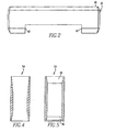
- the straight bore flow holes (with inlet chamfering) of the '507 patent debris filter bottom nozzle design were replaced by this invention with venturi flow holes, a cross section of which is shown in Figure 4 .
- the venturis 54 were constructed of relatively large-radii rounded inlets and outlets, either tangent or non-tangent to the bore.
- the venturi flow holes improved the nozzle 12 hydraulic performance, significantly reducing pressure drop.
- High pressure drop testing, extrapolated to reactor core flow conditions (500,000 Reynold's Number) has shown the improved debris filter bottom nozzle with venturi flow holes to reduce pressure drop and corresponding loss coefficient by approximately 53%.
- the venturi constricted throat diameters are equivalent to the flow hole bores of the standard debris filter bottom nozzle of the '507 patent design, debris filtering was not compromised.
- the straight bore flow holes with single inlet chamfering that was described in the '507 patent, was replaced with double inlet chamfers 56 and a single outlet chamfer 58 to form the venturi 54 shown in Figure 5 .
- the angles of the chamfers were optimized to provide the lowest pressure drop. In effect, they approximate a curved surface and streamline the flow through the holes 48. Controlling and inspecting the curved geometry is difficult and expensive.
- the inventors hereof have found, through computational Fluid Dynamics and experimentation, that as little as two straight chamfers, if configured properly, could develop flow similar to the curved geometry and result in a similar reduced pressure drop, with less cost.
- the preferred chamfer design is shown in the following table where Chamfer A is the chamfer closest to the inlet, Chamfer B is the chamfer adjacent Chamfer A and Chamfer C is at the outlet of the flow through holes.
- the plate thickness is also shown.
- the nominal values define the intended dimensions. The minimum and maximum values take into consideration the tolerances and provide acceptable ranges for the chamfer lengths.
- angles and dimensions are expressed as a ratio of the chamfer length divided by plate thickness L/T.
- Angle Chamfer L/T Maximum Minimum Chamfer A 2.33 x B 0.071 0.020 Chamfer B 15°+/- 3° 0.104 0.017 Chamfer C 0.67 x B 0.258 0.101
- This new flowthrough hole design improved the nozzle hydraulic performance, significantly reducing pressure drop.
- High temperature pressure drop testing extrapolated to reactor core flow conditions (500,000 Reynold's Number), has shown that the reduced pressure drop debris filter bottom nozzle of this invention, with these improved flow holes, reduced pressure drop and corresponding loss coefficient by 47% over that achieved by the '507 patent design.
- the double chamfer design provides a slight increase in pressure drop over the smooth curved venturi design shown in Figure 4 , it provides a significant improvement in the manufacturability of the nozzle and a reduction in cost.
- the new flow hole bore diameters at their most constricted point are equal to the flow hole bores of the '507 patent, debris filtering is not compromised. When manufacturability, inspectability and cost are considered, this design proves to provide consistent and reproducible pressure drop reduction.
- One additional conventional function of the bottom nozzle plate 46 is to capture the fuel rods 22, that is, to prevent them from dropping through the bottom nozzle 12.
- the fuel rods 22 are held by the grids 20 above the bottom nozzle 12 as seen in Figure 1 .
- the grids 20 commonly loosen their grip on the fuel rods 22 and some drop down on the top of the bottom nozzle plate 46.
- the fuel rods 22 are lined with the ligaments or sections 60 of the plate 46 between the flow holes 48.
- the flow holes 48 are packed in a density of approximately ⁇ 2.56 per cm 2 (16 per square inch).
- the sections 60 of the plate 46 extending between the flow holes 48 have a maximum dimension of 0,25 cm (1/10 inch).
- the terminal end of the lower end plug 30 was larger in diameter, then the section 60 of the plate 46 between the flow holes 48 would have to be larger in size in order to avoid the plug ends from covering portions of the adjacent holes 48. This would undoubtedly translate into fewer holes and an increase in pressure drop.
Landscapes
- Physics & Mathematics (AREA)
- Engineering & Computer Science (AREA)
- Plasma & Fusion (AREA)
- General Engineering & Computer Science (AREA)
- High Energy & Nuclear Physics (AREA)
- Structure Of Emergency Protection For Nuclear Reactors (AREA)
- Fuel-Injection Apparatus (AREA)
- Nozzles (AREA)
- Filtration Of Liquid (AREA)
Description
- The present invention relates generally to nuclear reactors and, more particularly, is concerned with a debris filter bottom nozzle for a nuclear fuel assembly.
- During manufacturing, subsequent installation and repair of components comprising a nuclear reactor coolant circulation system, diligent effort is made to help assure removal of all debris from the reactor vessel and its associated systems, which circulate coolant throughout the primary reactor coolant loop under various operating conditions. Although elaborate procedures are carried out to help assure debris removal, experience shows that in spite of the safeguards used to effect such removal, some chips and metal particles still remain hidden in the systems. Most of the debris consists of metal turnings, which were probably left in the primary system after steam generator repair or replacement.
- In particular, fuel assembly damage due to debris trapped at the lowermost grid has been noted in several reactors in recent years. Debris enters through the fuel assembly bottom nozzle flow holes from the coolant flow openings in the lower core support plate when the plant is started up. The debris tends to become lodged in the lowermost support grid of the fuel assembly within the spaces between the "egg crate" shaped cell walls of the grid and the lower end portions of the fuel rod tubes. The damage consists of fuel rod tube perforations caused by fretting of the debris in contact with the exterior of the tube. Debris also becomes entangled in the nozzle plate holes and the flowing coolant causes the debris to gyrate, which tends to cut through the cladding of the fuel rods.
- Several different approaches have been proposed and tried for carrying out the removal of debris from nuclear reactors. Many of these approaches are discussed in
U.S. Patent No. 4, 096,032 to Mayers et al. Others are illustrated and described in the various patents cross-referenced, inU.S. Patent No. 4,900,507 , assigned to the instant assignee. Still further approaches are disclosed inUS 2003/0 043 954 A1 and inEP 0 669 624 A1 . While all of the approaches described in the cited patent and cross references operate reasonably well and generally achieve their objectives under the range of operating conditions for which they were designed, a need still exists for a further improved approach to the problem of debris filtering in nuclear reactors, to address an improved reduction in pressure drop across the bottom nozzle that is required for more advanced fuel designs currently going under development. - The present invention provides a debris filter bottom nozzle in a fuel assembly designed to satisfy the aforementioned needs. The bottom nozzle of the present invention includes a nozzle plate employing the concept of having flow holes smaller in diameter than have been otherwise used prior to that disclosed in
U.S. Patent No. 4,900,507 , with a further improved reduction in pressure drop across the nozzle plate. The flow holes are preferably about 0,48 cm (0.190 inch) in diameter at their narrowest constriction, which makes them sized to filter out debris which otherwise collects primarily in the sections between the bottom nozzle and the lowermost grid and in the unoccupied spaces of the lowermost grid and causes fuel rod fretting failures. As noted inU.S. Patent No. 4,900,507 ('507 patent), unexpectedly, this concept reduces pressure drop of the debris filter bottom nozzle as compared to the prior art bottom nozzle, although the total flow area through the bottom nozzle with this design is less than the total flow area through the prior art bottom nozzle. Significantly greater flow area is provided by the debris filter bottom nozzle pattern of smaller flow holes than by the prior art bottom nozzle pattern of larger flow holes in the local areas of the respective nozzle plates directly above the coolant inlet flow holes in the reactor lower core plate. - This invention provides a venturi contour to the flow holes to further reduce the pressure drop across the bottom nozzle plate.
- The inlet through the flowthrough hole is provided with a double chamfer, with the angles between the double chamfer optimized to provide the lowest pressure drop. The double chamfer approximates a radius, i.e., a curve, without the attendant expense and difficulties of machining a curved surface, which streamlines the flow through the holes.
- Accordingly, the present invention is directed to a debris filter bottom nozzle useful in a fuel assembly for a nuclear reactor wherein the fuel assembly includes a plurality of nuclear fuel rods, at least a lowermost grid supporting the fuel rods in an organized array and having unoccupied spaces defined therein allowing flow of fluid coolant therethrough. The debris filter bottom nozzle is disposed adjacent to and below the grid and below lower ends of the fuel rods. The bottom nozzle comprises a nozzle plate fixed on support means facing towards a lowermost grid and having defined therethrough a plurality of flow apertures individually sized so that most debris larger in size than the maximum dimension of the unoccupied spaces through the lowermost grid are captured below, within or proximate the aperture outlet orifice. In this way most of the debris being carried by the liquid coolant through the nozzle plate is small enough to pass through the unoccupied grid spaces, whereas most debris being carried by the liquid coolant which is large enough to not pass through the unoccupied grid spaces and collect in the grid, will not pass through the flow apertures or will be retained proximate the outlets of the flow apertures. A reduction in pressure drop across the bottom nozzle plate is achieved by establishing a venturi contour in the flowthrough holes. Further enhancement of the manufacturability and inspectability of the design of this invention is established by providing a chamfer on the outlet side of the flowthrough holes and a double chamfer on the inlet side.
- A further understanding of the invention can be gained from the following description of the preferred embodiments when read in conjunction with the accompanying drawings in which:
-
Figure 1 is an elevational view, partially in section, of a fuel assembly in which is incorporated the preferred embodiment of the debris trap of the present invention, the assembly being illustrated in vertically shortened form, with parts broken away for clarity; -
Figure 2 is a side view of a bottom nozzle support skirt of this invention; -
Figure 3 is a top view of the bottom nozzle plate of this invention; -
Figure 4 is a side view of a cutaway section ofFigure 3 taken along the lines A-A thereof that shows a venturi flowthrough hole with curved inlet and outlet features; -
Figure 5 is a side view of a cutaway section ofFigure 3 taken along the lines A-A thereof that shows a flowthrough hole with a double inlet chamfer and single outlet chamfer; - In the following description, like reference characters designate like or corresponding parts throughout the several views of the drawings. Also in the following description, it is to be understood that such terms as "forward", "rearward", "left", "right", "upwardly", "downwardly" and the like are words of convenience and are not to be construed as limiting terms.
- Referring now to the drawings and particularly to
Figure 1 , there is shown an elevational view of the fuel assembly, represented in vertically shortened form and being generally designated byreference numeral 10. Thefuel assembly 10 is the type used in a pressurized water reactor and has a structural skeleton which, at its lower end, includes the debrisfilter bottom nozzle 12 of the present invention (which will be described later in detail). Thebottom nozzle 12 supports thefuel assembly 10 on a lowercore support plate 14 in the core region of the nuclear reactor (not shown). In addition to thebottom nozzle 12, the structural skeleton of thefuel assembly 10 also includes a top nozzle 16 at its upper end and a number of guide tubes orthimbles 18, which extend longitudinally between the bottom andtop nozzles 12 and 16 and at opposite ends are rigidly attached thereto. - The
fuel assembly 10 further includes a plurality oftraverse grids 20 axially-spaced along, and mounted to, thegrid thimble tubes 18 and an organized array ofelongated fuel rods 22 traversely-spaced and supported by thegrids 20. Also, theassembly 10 has aninstrumentation tube 24 located in the center thereof and extending between, and mounted to, the bottom andtop nozzles 12 and 16. With such an arrangement of parts,fuel assembly 10 forms an integral unit capable of being conveniently handled without damaging the assembly parts. - As mentioned above, the
fuel rods 22 in the array thereof in theassembly 10 are held in spaced relationship with one another by thegrids 20 spaced along the fuel assembly length. Eachfuel rod 22 includesnuclear fuel pellets 26 and is closed at its opposite ends by upper andlower end plugs pellets 26 are maintained in a stack by aplenum spring 32 disposed between theupper end plug 28 and the top of the pellet stack. Thefuel pellets 26, composed of fissile material, are responsible for creating the reactive power of the reactor. A liquid moderator/coolant such as water or water containing boron, is pumped upwardly through a plurality of flow openings in thelower core plate 14 to the fuel assembly. Thebottom nozzle 12 of thefuel assembly 10 passes the coolant upwardly through theguide tubes 18 and along thefuel rods 22 of the assembly in order to extract heat generated therein for the production of useful work. - To control the fission process, a number of
control rods 34 are reciprocally moveable in theguide thimbles 18 located at predetermined positions in thefuel assembly 10. Specifically, a rodcluster control mechanism 36 positioned above the top nozzle 16 supports thecontrol rods 34. The control mechanism has an internally threadedcylindrical member 37 with a plurality of radially-extending flukes orarms 38. Eacharm 38 is interconnected to controlrod 34 such that thecontrol rod mechanism 36 is operable to move the control rods vertically in theguide thimbles 18 to thereby control the fission process in thefuel assembly 10, all in a well known manner. - As mentioned above, fuel assembly damage due to debris trapped at or below the lowermost one of the
grids 20 supporting the fuel bearing regions of the fuel rods has been found to be a problem. Therefore, to prevent occurrence of such damage, it is highly desirable to minimize the debris that passes through the bottom nozzle flow holes or the interfaces between the outlets of the bottom nozzle flow holes and the adjoining structures. - The present invention relates to a
bottom nozzle 12 which, in addition to supporting thefuel assembly 10 on thelower core plate 14, also contains features which function to filter out potentially damaging size debris from the coolant flow passed upwardly through the bottom nozzle with a a reduction in pressure drop over that experienced in the design of the '507 patent. Thebottom nozzle 12 includes support means, for example theskirt 40 shown inFigure 2 . The support means,skirt 40 in this embodiment, includes a plurality ofcorner legs 42 for supporting thefuel assembly 10 on thelower core plate 14. A generally rectangularplanar plate 46 is suitably attached, such as by welding, to theupper surface 44 of thesupport skirt 40. In thenozzle plate 46 of the debris filterbottom nozzle 12 of the present invention, a large number ofsmall holes 48 are concentrated in the area of the flow holes through the lowercore support plate 14 and are sized to filter out damaging size debris without adversely affecting flow or pressure drop through the bottomnozzle adapter plate 46 and across thefuel assembly 10. In this respect, the debris filterbottom nozzle 12 of this invention is very similar to that described inU.S. Patent No. 4,900,507 , assigned to the assignee of this invention. In the debris filterbottom nozzle 12 of the '507 patent, the flow holes 58 included inlet chamfers at each flow hole. In other respects, the flow holes 48 of the '507 patent were preferably uniform in cross-sectional size and defined a pattern which substantially covers every portion of theplate 46 across its length and breadth. - The diameter of the flow holes 48 does not allow passage of most of the debris that is of a size typically caught in the
lowermost support grid 20. If the debris is small enough to pass through these plate flow holes 48, it will in most cases also pass through thegrids 20 since the diameter of the flow holes 48 is small enough to catch most of the debris having a cross section larger than that of the unoccupied spaces through a cell of thesupport grid 20. Such unoccupied spaces are typically found in adjacent corners formed by the interleaved straps composing thegrid 20 and are bounded by the corners, respective dimples and spring formed on the grip straps and thefuel rods 22, which extend through the grid cells. By insuring that most of the debris is small enough to pass through the grids unoccupied spaces, the debris filterbottom nozzle 12 of the present invention thereby significantly reduces the potential for debris-induced fuel rod failures. It should be appreciated that the improvement of this invention does not require that the narrowest cross section of the flow throughholes 48 in thenozzle plate 46 be equal or smaller than the largest cross sectional dimension of the unoccupied spaces through a cell of thesupport grid 20, especially when the outlet of the flow throughholes 48 effectively operate in conjunction with adjoining structures to further constrict the flow path. For example, when protective grids are employed, which typically are located approximately 0,064 to 0,318 cm (.025 to 0.125 inch) above thenozzle plate 46, the grid straps further delimit the flow and trap debris in the area between the protective grid and the nozzle plate. - Based upon a comprehensive analysis of fuel surveillance underwater television photographs of fuel assemblies from reactors experiencing debris-induced fuel rod failures, a nominal diameter for the flow holes 48 of about 0,48 cm (0.190 inch) was selected, with 0.48 +/- 0.02 cm (0190 +/- 0.008 inch) being preferred). It is possible for the
holes 48 to be made somewhat smaller in diameter. All observed primary debris-induced fuel rod failures were at or below the lowermost grid and appear to be caused by debris somewhat larger than 0,48 cm (0.190 inch) in width. Other smaller debris typically present in the reactor coolant systems is believed to be relatively delicate in nature and not likely to cause rod damage since little or no significant damage can be observed above the lowermost grid. The evidence suggests that, heretofore, the damaging size debris is effectively stopped by thelowermost grid 20. The debris filterbottom nozzle 12, with approximately 0,48 cm (0.190 inch) diameter sized flow holes 48 defined in thebottom nozzle plate 46, is expected to reduce by 90% the potential rod damaging metallic debris carried into fuel assemblies by the primary coolant flow. Such estimate may be conservative since it appears likely that debris substantially larger than 0,48 cm (0,190 inch) in width may do a disproportionate amount of fuel rod damage. - Referring to
Figure 3 , it can be seen that, in addition to the large number of flow holes 48, theplate 46 includes one centralinstrumentation tube hole 50 and a number of guide thimble holes 52. The flow holes 48 described in the '507 patent included a long taper inlet chamfer, about 0,36 cm (0.140 inch) in length and forming an angle of approximately 15° +/- 3° to the axis of thehole 48. The chamfer on the inlet was employed on each of the flow holes 48 to optimize the flow, i.e., minimize the loss coefficient increase due to the higher frictional affect inherent with the smaller flow holes 48. Thelonger chamfer 50 was thought to prevent the flow stream from reattaching within the adapter plate holes 48 and increasing pressure drop across thefuel assembly 10. Any increase in pressure drop across the fuel assembly, with the debris filterbottom nozzle 12 compared to an assembly with the conventional bottom nozzle, would be undesirable and very likely unacceptable. Although the debris filter bottom nozzle of the '507 patent provided smaller flow holes, the flow holes were more numerous than in the prior original bottom nozzle design. For the fuel assemblies to which it was adapted, the total flow area through the '507 patent debris filter bottom nozzle was not significantly reduced. However, the debris filter bottom nozzle flow area of the '507 patent design and the corresponding pressure drop have proven to be a limiting constraint for more advanced fuel designs. - The debris filter bottom nozzle was further improved by this invention by optimizing the coolant flow paths through the
nozzle plate 46. The straight bore flow holes (with inlet chamfering) of the '507 patent debris filter bottom nozzle design were replaced by this invention with venturi flow holes, a cross section of which is shown inFigure 4 . Theventuris 54 were constructed of relatively large-radii rounded inlets and outlets, either tangent or non-tangent to the bore. The venturi flow holes improved thenozzle 12 hydraulic performance, significantly reducing pressure drop. High pressure drop testing, extrapolated to reactor core flow conditions (500,000 Reynold's Number), has shown the improved debris filter bottom nozzle with venturi flow holes to reduce pressure drop and corresponding loss coefficient by approximately 53%. Furthermore, because the venturi constricted throat diameters are equivalent to the flow hole bores of the standard debris filter bottom nozzle of the '507 patent design, debris filtering was not compromised. - Past experience has shown pressure drop differences in nozzles made to identical drawings by different suppliers. In one case, the difference was traced to the manufacturing processes and differing deburr methods. One of the methods combined with an outlet chamfer in addition to the inlet chamfer could have provided a nozzle that delivered the pressure drop required for the advanced fuel designs currently under development. However, specification, control and inspection of this manual deburr process proved to be very difficult. The venturi
flowthrough hole design 54 of the debris filterbottom nozzle 12 was enhanced, from a manufacturing point of view, by optimizing the coolant flow paths through thenozzle flow plate 46. The straight bore flow holes, with single inlet chamfering that was described in the '507 patent, was replaced with double inlet chamfers 56 and asingle outlet chamfer 58 to form theventuri 54 shown inFigure 5 . The angles of the chamfers were optimized to provide the lowest pressure drop. In effect, they approximate a curved surface and streamline the flow through theholes 48. Controlling and inspecting the curved geometry is difficult and expensive. The inventors hereof have found, through computational Fluid Dynamics and experimentation, that as little as two straight chamfers, if configured properly, could develop flow similar to the curved geometry and result in a similar reduced pressure drop, with less cost. The preferred chamfer design is shown in the following table where Chamfer A is the chamfer closest to the inlet, Chamfer B is the chamfer adjacent Chamfer A and Chamfer C is at the outlet of the flow through holes. The plate thickness is also shown. The nominal values define the intended dimensions. The minimum and maximum values take into consideration the tolerances and provide acceptable ranges for the chamfer lengths.Angle Nominal Length (cm) Maximum Length (cm) Minimum Length (cm) Chamfer A 35° ± 3° 0.043 cm (0.017 in) 0.099 cm (0.039 in) 0.030 cm (0.012 in) Chamfer B 15° ± 3° 0.099 cm (0.039 in) 0.145 cm (0.057 in) 0.025 cm (0.010 in) Chamfer C 10° ± 3° 0.2159 cm (00.085 in) 0.361 cm (0.142 in) 0.15 cm (0.059 in) Plate Thickness -- 1.422 cm (0.560 in) 1.481 cm (0.583 in) 1.397 cm (0.550 in) Angle Chamfer L/T Maximum Minimum Chamfer A 2.33 x B 0.071 0.020 Chamfer B 15°+/- 3° 0.104 0.017 Chamfer C 0.67 x B 0.258 0.101 - This new flowthrough hole design improved the nozzle hydraulic performance, significantly reducing pressure drop. High temperature pressure drop testing, extrapolated to reactor core flow conditions (500,000 Reynold's Number), has shown that the reduced pressure drop debris filter bottom nozzle of this invention, with these improved flow holes, reduced pressure drop and corresponding loss coefficient by 47% over that achieved by the '507 patent design. While the double chamfer design provides a slight increase in pressure drop over the smooth curved venturi design shown in
Figure 4 , it provides a significant improvement in the manufacturability of the nozzle and a reduction in cost. Furthermore, because the new flow hole bore diameters at their most constricted point are equal to the flow hole bores of the '507 patent, debris filtering is not compromised. When manufacturability, inspectability and cost are considered, this design proves to provide consistent and reproducible pressure drop reduction. - One additional conventional function of the
bottom nozzle plate 46 is to capture thefuel rods 22, that is, to prevent them from dropping through thebottom nozzle 12. At initial startup, thefuel rods 22 are held by thegrids 20 above thebottom nozzle 12 as seen inFigure 1 . However, after the reactor is operated for a time, thegrids 20 commonly loosen their grip on thefuel rods 22 and some drop down on the top of thebottom nozzle plate 46. As seen inFigure 3 , thefuel rods 22 are lined with the ligaments orsections 60 of theplate 46 between the flow holes 48. The flow holes 48 are packed in a density of approximately < 2.56 per cm2 (16 per square inch). Thesections 60 of theplate 46 extending between the flow holes 48 have a maximum dimension of 0,25 cm (1/10 inch). If thefuel rods 22, having maximum diameter of about 1,02 cm (0.400 inch), were located above the flow holes 48, then when falling down on theplate 46, they would plug up the holes and cause an increase in pressure drop. The lower end plugs 30 of thefuel rods 22, which rest on thesections 60 of theplate 46, have a terminal end diameter of approximately 0,38 cm (0.150 inch) and a tapered axial cross-sectional shape as seen inFigure 1 , which does not block theholes 48. However, if the terminal end of thelower end plug 30 was larger in diameter, then thesection 60 of theplate 46 between the flow holes 48 would have to be larger in size in order to avoid the plug ends from covering portions of the adjacent holes 48. This would undoubtedly translate into fewer holes and an increase in pressure drop. - While specific embodiments of the invention have been described in detail, it will be appreciated by those skilled in the art that various modifications and alternatives to those details could be developed in light of the overall teachings of the disclosure. Accordingly, the particular embodiments disclosed are meant to be illustrative only and not limiting as to the scope of the invention.
Claims (9)
- A nuclear reactor fuel assembly (10) including a plurality of elongated nuclear fuel rods (22) having an extended axial length, at least a lowermost grid (20) supporting said fuel rods in an organized array and having unoccupied spaces defined therein adapted to allow flow of fluid coolant therethrough and past said fuel rods (22) when said fuel assembly is installed in the nuclear reactor and a plurality of guide thimbles (18) extending along said fuel rods (22) through and supporting said lowermost grid (20), and a debris filter bottom nozzle (12) being designed to be disposed below said lowermost grid (20), below lower ends of said fuel rods (22), supporting said guide thimbles(18) and adapted to allow flow of fluid coolant into said fuel assembly (10), said debris filter bottom nozzle (12) comprising a substantially horizontal plate (46) extending substantially transverse to the axis of the fuel rods and having an upper face directed toward said lowermost grid (20), said upper face of said plate(46) having defined therethrough at least two different types of holes, the first type being a plurality of holes (52) receiving lower ends of said guide thimbles (18) where they are supported by said plate (46) and the second type being a plurality of flow through holes (48) sized to filter out debris of damage-inducing size and extending completely through said plate (46) for the passage of coolant fluid from a lower face of said plate to the upper face of said plate, each of said coolant flow through holes (48) extending substantially in the axial direction of said fuel rods, in fluid communication with said unoccupied spaces, at least some of said coolant flow through holes have a profile substantially of a venturi (54) with an inlet end (56) in the lower face of said plate and an outlet end (58) in the upper face of said plate wherein the venturi is substantially formed by a chamfer in said inlet (56) end and a chamfer in said outlet end (58), characterized in that
the flow through holes 48 are sized in diameter to filter out debris of a size which otherwise collects in the unoccupied spaces of the lowermost grid (20) and
the inlet end chamfer (56) is a double angle chamfers, including a first chamfer closest to the inlet and a second chamfer adjacent said first chamfer, said double angle chamfer approximating a curved surface. - The nuclear reactor fuel assembly of claim 1 wherein all of the coolant flow through holes (48) not associated with a guide thimble include the double angle inlet chamfer.
- The nuclear reactor fuel assembly of claim 1 wherein the chamfers have the following dimensions and angles relative to a flow axis of the flow through hole (48) where Chamfer A is the chamfer closest to the inlet of the flow through hole (48) and Chamfer B is the chamfer adjacent Chamfer A, spaced from the inlet.
Angle Nominal Length (in.) Maximum Length (in.) Minimum Length (in.) Chamfer A 35° ± 3° 0.043 cm (0.017 in) 0.099 cm (0.039 in) 0,030 cm (0.012 in) Chamfer B 15° ± 3° 0.099 cm (0.039 in) 0.145 cm (0.057 in) 0.025 cm (0.010 in) - The nuclear reactor fuel assembly of claim 1 wherein the chamfers have the following relative dimensions and angles with regard to a flow axis of the flow through hole (48) where Chamfer A is the chamfer closest to the inlet, Chamfer B is the chamfer adjacent Chamfer A and chamfer C is at the outlet of the flow through holes (48) and L/T is the length of the chamfer divided by the thickness of the plate.
Angle Chamfer L/T Maximum Minimum Chamfer A 2.33 x B 0.071 0.020 Chamfer B 15° +/- 3° 0.104 0.017 - The nuclear reactor fuel assembly of claim 3 wherein the chamfers have the following ditensions and angles relative to a flow axis of the flow through hole (48) where Chamfer A is the chamfer closest to the inlet, Chamfer B is the chamfer adjacent chamfer A and Chamfer C is at the outlet of the flow through holes (48).
Angle Nominal Length (in.) Maximum Length (in.) Minimum Length (in.) Chamfer A 35° ± 3° 0.043 cm (0.017 in) 0.099 cm (0.039 in) 0.030 cm (0.012 in) Chamfer B 15 ± 3° 0.099 cm (0.039 in) 0.145 cm (0.057 in) 0.025 cm (0.010 in) Chamfer C 10° ± 3° 0.2159 cm (0.085 in) 0.361 cm (0.142 in) 0.15 cm (0.059 in) - The nuclear reactor fuel assembly of claim 4 wherein the chamfers have the following relative dimensions and angles with regard to a flow axis of the flow through hole (48) where Chamfer A is the chamfer closest to the inlet, Chamfer B is the chamfer adjacent Chamfer A and Chamfer C is a t the outlet of the flow through holes (48) and L/T is the length of the chamfer divided by the thickness of the plate (46).
Chamfer L/T Angle Maximum Minimum Chamfer A 2.33 x B 0.071 0.020 Chamfer B 15° +/- 3° 0.104 0.017 Chamfer C 0.67 x B 0.258 0.101 - The nuclear reactor fuel assembly of claim 1 including support means (40, 42) adapted to support said fuel assembly (10) when installed in the nuclear reactor with said plate (46) fixed at its periphery on said support means.
- The nuclear reactor fuel assembly of any of claims 1 to 7 wherein the coolant flow through holes (48) have a 0.48 +/-0.02 cm (0.190 +/- 0.008 inch) or less diameter at their narrow-est cross-section.
- The nuclear reactor fuel assembly of claim 8 wherein the coolant flow through holes (48) are packed in a density of about 2.56 per cm3 (16 per square inch).
Applications Claiming Priority (2)
| Application Number | Priority Date | Filing Date | Title |
|---|---|---|---|
| US10/751,349 US7822165B2 (en) | 2004-01-05 | 2004-01-05 | Nuclear fuel assembly debris filter bottom nozzle |
| US751349 | 2004-01-05 |
Publications (3)
| Publication Number | Publication Date |
|---|---|
| EP1551033A2 EP1551033A2 (en) | 2005-07-06 |
| EP1551033A3 EP1551033A3 (en) | 2010-01-20 |
| EP1551033B1 true EP1551033B1 (en) | 2012-03-07 |
Family
ID=34574825
Family Applications (1)
| Application Number | Title | Priority Date | Filing Date |
|---|---|---|---|
| EP04030857A Active EP1551033B1 (en) | 2004-01-05 | 2004-12-28 | Nuclear fuel assembly debris filter bottom nozzle |
Country Status (7)
| Country | Link |
|---|---|
| US (1) | US7822165B2 (en) |
| EP (1) | EP1551033B1 (en) |
| JP (1) | JP3993599B2 (en) |
| KR (1) | KR101113448B1 (en) |
| CN (1) | CN100592434C (en) |
| BR (1) | BRPI0405881B1 (en) |
| ES (1) | ES2380669T3 (en) |
Families Citing this family (30)
| Publication number | Priority date | Publication date | Assignee | Title |
|---|---|---|---|---|
| US9620249B2 (en) * | 2007-08-31 | 2017-04-11 | Global Nuclear Fuel—Americas, LLC | Debris shield upper tie plate for nuclear fuel assembly and method to shield assembly from debris |
| US8116423B2 (en) | 2007-12-26 | 2012-02-14 | Thorium Power, Inc. | Nuclear reactor (alternatives), fuel assembly of seed-blanket subassemblies for nuclear reactor (alternatives), and fuel element for fuel assembly |
| KR101474864B1 (en) | 2007-12-26 | 2014-12-19 | 토륨 파워 인코포레이티드 | Nuclear reactor(variants), fuel assembly consisting of driver-breeding modules for a nuclear reactor(variants) and a fuel cell for a fuel assembly |
| FR2932600B1 (en) * | 2008-06-11 | 2010-06-04 | Areva Np | LOWER NUCLEAR FUEL ASSEMBLY TIP |
| EP2372717B1 (en) | 2008-12-25 | 2016-04-13 | Thorium Power, Inc. | Fuel assembly for a light-water nuclear reactor and light-water nuclear reactor |
| US20110164719A1 (en) | 2010-01-05 | 2011-07-07 | Westinghouse Electric Company, Llc | Nuclear fuel assembly debris filter bottom nozzle |
| US20110243293A1 (en) * | 2010-03-31 | 2011-10-06 | Peter Ray Diller | Systems and Methods for Servicing a Fuel Assembly in a Light Water Reactor |
| US10192644B2 (en) | 2010-05-11 | 2019-01-29 | Lightbridge Corporation | Fuel assembly |
| WO2011143172A1 (en) | 2010-05-11 | 2011-11-17 | Thorium Power, Inc. | Fuel assembly with metal fuel alloy kernel and method of manufacturing thereof |
| US10170207B2 (en) | 2013-05-10 | 2019-01-01 | Thorium Power, Inc. | Fuel assembly |
| CN102476260A (en) * | 2010-11-23 | 2012-05-30 | 中核建中核燃料元件有限公司 | Manufacturing method for chip-resistant plate of lower tube seat |
| WO2013053128A1 (en) * | 2011-10-14 | 2013-04-18 | 中科华核电技术研究院有限公司 | Bottom nozzle filter device and debris-resistant bottom nozzle using the device |
| JP6270732B2 (en) * | 2011-12-12 | 2018-01-31 | ドミニオン エンジニアリング, インク.Dominion Engineering, Inc. | Particulate removal system |
| US20130272477A1 (en) * | 2012-04-15 | 2013-10-17 | Julius M. Ullmann | Pressurized Water Reactor with Skirted Lower End Fitting and Filter Plate |
| CN102651243B (en) * | 2012-05-14 | 2015-08-05 | 中科华核电技术研究院有限公司 | A kind of bottom nozzle and bottom device |
| US9847144B1 (en) * | 2014-04-03 | 2017-12-19 | Westinghouse Electric Company Llc | Low pressure drop nuclear fuel assembly bottom nozzle |
| CN104329067B (en) * | 2014-08-20 | 2018-06-01 | 中国石油化工股份有限公司 | A kind of heavy crude heat extraction technique and its dedicated unit |
| CN104200851B (en) * | 2014-09-16 | 2016-09-07 | 中国科学院合肥物质科学研究院 | A kind of support grid of liquid heavy metal cooled reactor take-up assembly fuel rod |
| WO2016093487A1 (en) * | 2014-12-11 | 2016-06-16 | 한전원자력연료 주식회사 | Lower end fixing body for improving flow path resistance of in-core detector |
| CN105469838B (en) * | 2015-12-23 | 2018-01-05 | 中广核研究院有限公司 | Fuel assembly and its fuel rod for improving nuclear reactor safety |
| KR102523408B1 (en) * | 2017-03-17 | 2023-04-18 | 웨스팅하우스 일렉트릭 컴퍼니 엘엘씨 | Fuel Assembly Debris Filtration Lower Nozzle |
| US10720246B2 (en) | 2017-04-20 | 2020-07-21 | Westinghouse Electric Company Llc | Fuel assembly arrangement for retaining fuel rod end plug to bottom nozzle |
| US10923237B2 (en) * | 2017-08-28 | 2021-02-16 | Global Nuclear Fuel—Americas, LLC | Debris filters for nuclear fuel assembly and method of using the same |
| RU2654531C1 (en) * | 2017-09-29 | 2018-05-21 | Акционерное общество "ТВЭЛ" (АО "ТВЭЛ") | Nuclear reactor fuel assembly |
| CN108010590B (en) * | 2017-12-18 | 2024-08-09 | 岭澳核电有限公司 | Protruding lower tube seat and fuel assembly |
| CN109935363B (en) * | 2017-12-19 | 2024-05-10 | 中国原子能科学研究院 | Fuel assembly and bottom device thereof and bottom tube seat applied to bottom device |
| CN109036604B (en) * | 2018-07-20 | 2024-01-16 | 中广核研究院有限公司 | Reactor core filtering device |
| CN109065194B (en) * | 2018-07-20 | 2024-09-03 | 中广核研究院有限公司 | Reactor core inlet flow distribution device |
| WO2020236702A2 (en) | 2019-05-21 | 2020-11-26 | Westinghouse Electric Company Llc | Bottom nozzle with internal debris filter |
| US20220215971A1 (en) * | 2019-05-23 | 2022-07-07 | Westinghouse Electric Company Llc | Debris filtering skirt arrangement for nuclear fuel assembly bottom nozzle and bottom nozzle including same |
Family Cites Families (31)
| Publication number | Priority date | Publication date | Assignee | Title |
|---|---|---|---|---|
| US3840051A (en) * | 1971-03-11 | 1974-10-08 | Mitsubishi Heavy Ind Ltd | Straightener |
| GB1548447A (en) * | 1976-09-06 | 1979-07-18 | Canadian Patents Dev | Apparatus for measuring the flow rate and/or viscosity of a fluid |
| US4684496A (en) * | 1984-11-16 | 1987-08-04 | Westinghouse Electric Corp. | Debris trap for a pressurized water nuclear reactor |
| US4684495A (en) * | 1984-11-16 | 1987-08-04 | Westinghouse Electric Corp. | Fuel assembly bottom nozzle with integral debris trap |
| US4664880A (en) * | 1984-12-07 | 1987-05-12 | Westinghouse Electric Corp. | Wire mesh debris trap for a fuel assembly |
| US4678627A (en) * | 1985-04-04 | 1987-07-07 | Westinghouse Electric Corp. | Debris-retaining trap for a fuel assembly |
| JPS61284696A (en) * | 1985-06-12 | 1986-12-15 | 株式会社日立製作所 | Fuel support metal and nuclear reactor |
| US4652425A (en) * | 1985-08-08 | 1987-03-24 | Westinghouse Electric Corp. | Bottom grid mounted debris trap for a fuel assembly |
| US4900507A (en) * | 1987-05-05 | 1990-02-13 | Westinghouse Electric Corp. | Nuclear fuel assembly debris filter bottom nozzle |
| US4832905A (en) * | 1988-04-15 | 1989-05-23 | Combustion Engineering, Inc. | Lower end fitting debris collector |
| US4997621A (en) * | 1989-03-13 | 1991-03-05 | General Electric Company | Lower tie plate with stepped holes to control pressure drop and flow distribution |
| FR2647944B1 (en) * | 1989-06-02 | 1993-12-10 | Framatome | FUEL ASSEMBLY OF A NUCLEAR REACTOR COMPRISING A DEVICE FOR RETAINING PARTICLES CONTAINED IN THE REACTOR COOLING FLUID |
| US5024806A (en) * | 1989-09-21 | 1991-06-18 | Westinghouse Electric Corp. | Enhanced debris filter bottom nozzle for a nuclear fuel assembly |
| US5094802A (en) * | 1989-10-13 | 1992-03-10 | B&W Fuel Company | Nuclear fuel assembly debris filter |
| US5071617A (en) * | 1989-12-11 | 1991-12-10 | Combustion Engineering, Inc. | Reduced flow resistance cast lower end fitting |
| SE465192B (en) * | 1989-12-15 | 1991-08-05 | Asea Atom Ab | BRAENSLEPATRON CARRIES A NUCLEAR WATER TYPE REACTOR |
| FR2656456B1 (en) * | 1989-12-21 | 1992-04-24 | Framatome Sa | LOWER TIP OF A FUEL ASSEMBLY OF A NUCLEAR REACTOR COOLED BY LIGHT WATER. |
| US5128098A (en) * | 1990-02-28 | 1992-07-07 | Hitachi, Ltd. | Fuel assembly |
| US5030412A (en) * | 1990-05-04 | 1991-07-09 | Advanced Nuclear Fuels Corporation | Fuel assembly debris screen |
| US5009839A (en) * | 1990-09-04 | 1991-04-23 | B&W Fuel Company | Nuclear fuel assembly bottom nozzle plate |
| FR2669459B1 (en) * | 1990-11-20 | 1994-02-04 | Framatome | LOWER FILTERING NOZZLE FOR A FUEL ASSEMBLY OF A NUCLEAR REACTOR COOLED BY LIGHT WATER. |
| US5488634A (en) * | 1994-02-10 | 1996-01-30 | General Electric Company | Lower tie plate debris catcher for a nuclear reactor |
| US5438598A (en) * | 1994-03-15 | 1995-08-01 | B&W Fuel Company | Combined lower end fitting and debris filter |
| US5473650A (en) * | 1994-04-15 | 1995-12-05 | General Electric Company | Lower tie plate debris catcher for a nuclear reactor |
| US5519745A (en) * | 1994-11-03 | 1996-05-21 | General Electric Company | Lower tie plate debris catcher for a nuclear reactor |
| US5528640A (en) * | 1994-11-07 | 1996-06-18 | General Electric Company | Low pressure double offset plate catcher for a nuclear reactor |
| US5748694A (en) * | 1996-03-26 | 1998-05-05 | General Electric Company | Fuel bundle filter for a nuclear reactor fuel bundle assembly |
| JP2002296379A (en) | 2001-03-30 | 2002-10-09 | Mitsubishi Heavy Ind Ltd | Nuclear reactor fuel assembly |
| US6608880B2 (en) * | 2001-07-17 | 2003-08-19 | Westinghouse Electric Co. Llc | Reduced pressure drop debris filter bottom nozzle for a fuel assembly of a nuclear reactor |
| JP4346842B2 (en) * | 2001-08-15 | 2009-10-21 | 三菱重工業株式会社 | Foreign matter filter for fuel assemblies for PWR reactors |
| US20110164719A1 (en) * | 2010-01-05 | 2011-07-07 | Westinghouse Electric Company, Llc | Nuclear fuel assembly debris filter bottom nozzle |
-
2004
- 2004-01-05 US US10/751,349 patent/US7822165B2/en active Active
- 2004-12-10 JP JP2004358216A patent/JP3993599B2/en not_active Expired - Fee Related
- 2004-12-28 EP EP04030857A patent/EP1551033B1/en active Active
- 2004-12-28 ES ES04030857T patent/ES2380669T3/en active Active
- 2004-12-30 BR BRPI0405881A patent/BRPI0405881B1/en not_active IP Right Cessation
- 2004-12-30 KR KR1020040116782A patent/KR101113448B1/en active IP Right Grant
-
2005
- 2005-01-05 CN CN200510004033A patent/CN100592434C/en active Active
Non-Patent Citations (1)
| Title |
|---|
| RICHARD LENK: "Fachlexikon ABC Physik", vol. 1, 1989, VERLAG HARRI DEUTSCH, THUN UND FRANKFURT/MAIN, ISBN: 3817110472, pages: 192 * |
Also Published As
| Publication number | Publication date |
|---|---|
| US7822165B2 (en) | 2010-10-26 |
| CN100592434C (en) | 2010-02-24 |
| BRPI0405881B1 (en) | 2017-04-04 |
| KR101113448B1 (en) | 2012-02-29 |
| JP3993599B2 (en) | 2007-10-17 |
| KR20050072054A (en) | 2005-07-08 |
| EP1551033A3 (en) | 2010-01-20 |
| EP1551033A2 (en) | 2005-07-06 |
| US20050157836A1 (en) | 2005-07-21 |
| CN1637956A (en) | 2005-07-13 |
| BRPI0405881A (en) | 2005-08-09 |
| ES2380669T3 (en) | 2012-05-17 |
| JP2005195577A (en) | 2005-07-21 |
Similar Documents
| Publication | Publication Date | Title |
|---|---|---|
| EP1551033B1 (en) | Nuclear fuel assembly debris filter bottom nozzle | |
| EP0289829B1 (en) | Nuclear fuel assembly with a debris-filter bottom nozzle | |
| US5024806A (en) | Enhanced debris filter bottom nozzle for a nuclear fuel assembly | |
| US4664880A (en) | Wire mesh debris trap for a fuel assembly | |
| US4828791A (en) | Nuclear fuel assembly debris resistant bottom nozzle | |
| US4678627A (en) | Debris-retaining trap for a fuel assembly | |
| US6608880B2 (en) | Reduced pressure drop debris filter bottom nozzle for a fuel assembly of a nuclear reactor | |
| EP2341509B1 (en) | Nuclear fuel assembly debris filter bottom nozzle | |
| US7889829B2 (en) | Nuclear fuel assembly protective grid | |
| EP3596735B1 (en) | Nuclear fuel assembly debris filtering bottom nozzle | |
| US8238511B2 (en) | Nuclear fuel assembly protective bottom grid | |
| US20200373025A1 (en) | Debris filtering arrangement for nuclear fuel assembly bottom nozzle and bottom nozzle including same | |
| US5438598A (en) | Combined lower end fitting and debris filter | |
| US11183310B2 (en) | Bottom nozzle of nuclear fuel assembly provided with flow holes by utilizing layered aircraft airfoil structure | |
| JPS63153492A (en) | Nuclear reactor | |
| JPH022976A (en) | Small fuel rod bundle for fuel assembly | |
| EP0200111B1 (en) | Improved boiling water nuclear reactor fuel assembly | |
| US20100226472A1 (en) | Nuclear fuel element and assembly | |
| EP1012851B1 (en) | Nuclear fuel assembly | |
| JPH057679B2 (en) |
Legal Events
| Date | Code | Title | Description |
|---|---|---|---|
| PUAI | Public reference made under article 153(3) epc to a published international application that has entered the european phase |
Free format text: ORIGINAL CODE: 0009012 |
|
| AK | Designated contracting states |
Kind code of ref document: A2 Designated state(s): AT BE BG CH CY CZ DE DK EE ES FI FR GB GR HU IE IS IT LI LT LU MC NL PL PT RO SE SI SK TR |
|
| AX | Request for extension of the european patent |
Extension state: AL BA HR LV MK YU |
|
| PUAL | Search report despatched |
Free format text: ORIGINAL CODE: 0009013 |
|
| AK | Designated contracting states |
Kind code of ref document: A3 Designated state(s): AT BE BG CH CY CZ DE DK EE ES FI FR GB GR HU IE IS IT LI LT LU MC NL PL PT RO SE SI SK TR |
|
| AX | Request for extension of the european patent |
Extension state: AL BA HR LV MK YU |
|
| 17P | Request for examination filed |
Effective date: 20100709 |
|
| AKX | Designation fees paid |
Designated state(s): DE ES FR SE |
|
| 17Q | First examination report despatched |
Effective date: 20100903 |
|
| GRAP | Despatch of communication of intention to grant a patent |
Free format text: ORIGINAL CODE: EPIDOSNIGR1 |
|
| GRAS | Grant fee paid |
Free format text: ORIGINAL CODE: EPIDOSNIGR3 |
|
| GRAA | (expected) grant |
Free format text: ORIGINAL CODE: 0009210 |
|
| AK | Designated contracting states |
Kind code of ref document: B1 Designated state(s): DE ES FR SE |
|
| REG | Reference to a national code |
Ref country code: DE Ref legal event code: R082 Ref document number: 602004036773 Country of ref document: DE Representative=s name: FLEUCHAUS & GALLO PARTNERSCHAFT, DE Ref country code: DE Ref legal event code: R082 Ref document number: 602004036773 Country of ref document: DE Representative=s name: FLEUCHAUS & GALLO PARTNERSCHAFT MBB, DE |
|
| REG | Reference to a national code |
Ref country code: DE Ref legal event code: R096 Ref document number: 602004036773 Country of ref document: DE Effective date: 20120503 |
|
| REG | Reference to a national code |
Ref country code: ES Ref legal event code: FG2A Ref document number: 2380669 Country of ref document: ES Kind code of ref document: T3 Effective date: 20120517 |
|
| REG | Reference to a national code |
Ref country code: SE Ref legal event code: TRGR |
|
| PLBE | No opposition filed within time limit |
Free format text: ORIGINAL CODE: 0009261 |
|
| STAA | Information on the status of an ep patent application or granted ep patent |
Free format text: STATUS: NO OPPOSITION FILED WITHIN TIME LIMIT |
|
| 26N | No opposition filed |
Effective date: 20121210 |
|
| REG | Reference to a national code |
Ref country code: DE Ref legal event code: R097 Ref document number: 602004036773 Country of ref document: DE Effective date: 20121210 |
|
| REG | Reference to a national code |
Ref country code: FR Ref legal event code: PLFP Year of fee payment: 12 |
|
| REG | Reference to a national code |
Ref country code: FR Ref legal event code: PLFP Year of fee payment: 13 |
|
| REG | Reference to a national code |
Ref country code: FR Ref legal event code: PLFP Year of fee payment: 14 |
|
| PGFP | Annual fee paid to national office [announced via postgrant information from national office to epo] |
Ref country code: DE Payment date: 20201222 Year of fee payment: 17 |
|
| REG | Reference to a national code |
Ref country code: DE Ref legal event code: R119 Ref document number: 602004036773 Country of ref document: DE |
|
| PG25 | Lapsed in a contracting state [announced via postgrant information from national office to epo] |
Ref country code: DE Free format text: LAPSE BECAUSE OF NON-PAYMENT OF DUE FEES Effective date: 20220701 |
|
| PGFP | Annual fee paid to national office [announced via postgrant information from national office to epo] |
Ref country code: SE Payment date: 20231228 Year of fee payment: 20 Ref country code: FR Payment date: 20231219 Year of fee payment: 20 |
|
| PGFP | Annual fee paid to national office [announced via postgrant information from national office to epo] |
Ref country code: ES Payment date: 20240110 Year of fee payment: 20 |