EP1550834A1 - Radiant panel - Google Patents
Radiant panel Download PDFInfo
- Publication number
- EP1550834A1 EP1550834A1 EP04028835A EP04028835A EP1550834A1 EP 1550834 A1 EP1550834 A1 EP 1550834A1 EP 04028835 A EP04028835 A EP 04028835A EP 04028835 A EP04028835 A EP 04028835A EP 1550834 A1 EP1550834 A1 EP 1550834A1
- Authority
- EP
- European Patent Office
- Prior art keywords
- aluminum
- tube
- copper
- radiator
- welds
- Prior art date
- Legal status (The legal status is an assumption and is not a legal conclusion. Google has not performed a legal analysis and makes no representation as to the accuracy of the status listed.)
- Granted
Links
- 229910052782 aluminium Inorganic materials 0.000 claims abstract description 34
- XAGFODPZIPBFFR-UHFFFAOYSA-N aluminium Chemical compound [Al] XAGFODPZIPBFFR-UHFFFAOYSA-N 0.000 claims abstract description 34
- RYGMFSIKBFXOCR-UHFFFAOYSA-N Copper Chemical compound [Cu] RYGMFSIKBFXOCR-UHFFFAOYSA-N 0.000 claims abstract description 29
- 229910052802 copper Inorganic materials 0.000 claims abstract description 29
- 239000010949 copper Substances 0.000 claims abstract description 29
- 238000010438 heat treatment Methods 0.000 claims abstract description 18
- 238000003466 welding Methods 0.000 claims abstract description 14
- 230000001154 acute effect Effects 0.000 claims abstract description 5
- 229910000881 Cu alloy Inorganic materials 0.000 claims description 13
- 229910000838 Al alloy Inorganic materials 0.000 claims description 12
- 238000000034 method Methods 0.000 claims description 11
- 230000005855 radiation Effects 0.000 claims description 5
- 239000002609 medium Substances 0.000 claims description 3
- 239000006163 transport media Substances 0.000 claims description 2
- 238000004381 surface treatment Methods 0.000 claims 1
- WYTGDNHDOZPMIW-RCBQFDQVSA-N alstonine Natural products C1=CC2=C3C=CC=CC3=NC2=C2N1C[C@H]1[C@H](C)OC=C(C(=O)OC)[C@H]1C2 WYTGDNHDOZPMIW-RCBQFDQVSA-N 0.000 abstract description 3
- 229910000831 Steel Inorganic materials 0.000 description 7
- 239000010959 steel Substances 0.000 description 7
- XLYOFNOQVPJJNP-UHFFFAOYSA-N water Substances O XLYOFNOQVPJJNP-UHFFFAOYSA-N 0.000 description 6
- 239000006096 absorbing agent Substances 0.000 description 3
- 239000000463 material Substances 0.000 description 3
- 238000009826 distribution Methods 0.000 description 2
- 238000004519 manufacturing process Methods 0.000 description 2
- 229910052751 metal Inorganic materials 0.000 description 2
- 239000002184 metal Substances 0.000 description 2
- 229910000906 Bronze Inorganic materials 0.000 description 1
- 238000010521 absorption reaction Methods 0.000 description 1
- 230000005540 biological transmission Effects 0.000 description 1
- 230000015572 biosynthetic process Effects 0.000 description 1
- 239000010974 bronze Substances 0.000 description 1
- KUNSUQLRTQLHQQ-UHFFFAOYSA-N copper tin Chemical compound [Cu].[Sn] KUNSUQLRTQLHQQ-UHFFFAOYSA-N 0.000 description 1
- 239000011888 foil Substances 0.000 description 1
- 150000002739 metals Chemical class 0.000 description 1
- 230000003287 optical effect Effects 0.000 description 1
- 239000003973 paint Substances 0.000 description 1
- 238000007747 plating Methods 0.000 description 1
- 230000001681 protective effect Effects 0.000 description 1
Images




Classifications
-
- F—MECHANICAL ENGINEERING; LIGHTING; HEATING; WEAPONS; BLASTING
- F28—HEAT EXCHANGE IN GENERAL
- F28F—DETAILS OF HEAT-EXCHANGE AND HEAT-TRANSFER APPARATUS, OF GENERAL APPLICATION
- F28F1/00—Tubular elements; Assemblies of tubular elements
- F28F1/10—Tubular elements and assemblies thereof with means for increasing heat-transfer area, e.g. with fins, with projections, with recesses
- F28F1/12—Tubular elements and assemblies thereof with means for increasing heat-transfer area, e.g. with fins, with projections, with recesses the means being only outside the tubular element
- F28F1/14—Tubular elements and assemblies thereof with means for increasing heat-transfer area, e.g. with fins, with projections, with recesses the means being only outside the tubular element and extending longitudinally
- F28F1/22—Tubular elements and assemblies thereof with means for increasing heat-transfer area, e.g. with fins, with projections, with recesses the means being only outside the tubular element and extending longitudinally the means having portions engaging further tubular elements
-
- B—PERFORMING OPERATIONS; TRANSPORTING
- B23—MACHINE TOOLS; METAL-WORKING NOT OTHERWISE PROVIDED FOR
- B23K—SOLDERING OR UNSOLDERING; WELDING; CLADDING OR PLATING BY SOLDERING OR WELDING; CUTTING BY APPLYING HEAT LOCALLY, e.g. FLAME CUTTING; WORKING BY LASER BEAM
- B23K26/00—Working by laser beam, e.g. welding, cutting or boring
- B23K26/20—Bonding
- B23K26/21—Bonding by welding
- B23K26/24—Seam welding
- B23K26/242—Fillet welding, i.e. involving a weld of substantially triangular cross section joining two parts
-
- B—PERFORMING OPERATIONS; TRANSPORTING
- B23—MACHINE TOOLS; METAL-WORKING NOT OTHERWISE PROVIDED FOR
- B23K—SOLDERING OR UNSOLDERING; WELDING; CLADDING OR PLATING BY SOLDERING OR WELDING; CUTTING BY APPLYING HEAT LOCALLY, e.g. FLAME CUTTING; WORKING BY LASER BEAM
- B23K26/00—Working by laser beam, e.g. welding, cutting or boring
- B23K26/20—Bonding
- B23K26/32—Bonding taking account of the properties of the material involved
-
- B—PERFORMING OPERATIONS; TRANSPORTING
- B23—MACHINE TOOLS; METAL-WORKING NOT OTHERWISE PROVIDED FOR
- B23K—SOLDERING OR UNSOLDERING; WELDING; CLADDING OR PLATING BY SOLDERING OR WELDING; CUTTING BY APPLYING HEAT LOCALLY, e.g. FLAME CUTTING; WORKING BY LASER BEAM
- B23K26/00—Working by laser beam, e.g. welding, cutting or boring
- B23K26/20—Bonding
- B23K26/32—Bonding taking account of the properties of the material involved
- B23K26/323—Bonding taking account of the properties of the material involved involving parts made of dissimilar metallic material
-
- F—MECHANICAL ENGINEERING; LIGHTING; HEATING; WEAPONS; BLASTING
- F24—HEATING; RANGES; VENTILATING
- F24D—DOMESTIC- OR SPACE-HEATING SYSTEMS, e.g. CENTRAL HEATING SYSTEMS; DOMESTIC HOT-WATER SUPPLY SYSTEMS; ELEMENTS OR COMPONENTS THEREFOR
- F24D3/00—Hot-water central heating systems
- F24D3/12—Tube and panel arrangements for ceiling, wall, or underfloor heating
- F24D3/14—Tube and panel arrangements for ceiling, wall, or underfloor heating incorporated in a ceiling, wall or floor
-
- F—MECHANICAL ENGINEERING; LIGHTING; HEATING; WEAPONS; BLASTING
- F28—HEAT EXCHANGE IN GENERAL
- F28D—HEAT-EXCHANGE APPARATUS, NOT PROVIDED FOR IN ANOTHER SUBCLASS, IN WHICH THE HEAT-EXCHANGE MEDIA DO NOT COME INTO DIRECT CONTACT
- F28D1/00—Heat-exchange apparatus having stationary conduit assemblies for one heat-exchange medium only, the media being in contact with different sides of the conduit wall, in which the other heat-exchange medium is a large body of fluid, e.g. domestic or motor car radiators
- F28D1/02—Heat-exchange apparatus having stationary conduit assemblies for one heat-exchange medium only, the media being in contact with different sides of the conduit wall, in which the other heat-exchange medium is a large body of fluid, e.g. domestic or motor car radiators with heat-exchange conduits immersed in the body of fluid
- F28D1/04—Heat-exchange apparatus having stationary conduit assemblies for one heat-exchange medium only, the media being in contact with different sides of the conduit wall, in which the other heat-exchange medium is a large body of fluid, e.g. domestic or motor car radiators with heat-exchange conduits immersed in the body of fluid with tubular conduits
- F28D1/047—Heat-exchange apparatus having stationary conduit assemblies for one heat-exchange medium only, the media being in contact with different sides of the conduit wall, in which the other heat-exchange medium is a large body of fluid, e.g. domestic or motor car radiators with heat-exchange conduits immersed in the body of fluid with tubular conduits the conduits being bent, e.g. in a serpentine or zig-zag
- F28D1/0477—Heat-exchange apparatus having stationary conduit assemblies for one heat-exchange medium only, the media being in contact with different sides of the conduit wall, in which the other heat-exchange medium is a large body of fluid, e.g. domestic or motor car radiators with heat-exchange conduits immersed in the body of fluid with tubular conduits the conduits being bent, e.g. in a serpentine or zig-zag the conduits being bent in a serpentine or zig-zag
-
- F—MECHANICAL ENGINEERING; LIGHTING; HEATING; WEAPONS; BLASTING
- F28—HEAT EXCHANGE IN GENERAL
- F28F—DETAILS OF HEAT-EXCHANGE AND HEAT-TRANSFER APPARATUS, OF GENERAL APPLICATION
- F28F21/00—Constructions of heat-exchange apparatus characterised by the selection of particular materials
- F28F21/08—Constructions of heat-exchange apparatus characterised by the selection of particular materials of metal
- F28F21/088—Constructions of heat-exchange apparatus characterised by the selection of particular materials of metal for domestic or space-heating systems
-
- B—PERFORMING OPERATIONS; TRANSPORTING
- B23—MACHINE TOOLS; METAL-WORKING NOT OTHERWISE PROVIDED FOR
- B23K—SOLDERING OR UNSOLDERING; WELDING; CLADDING OR PLATING BY SOLDERING OR WELDING; CUTTING BY APPLYING HEAT LOCALLY, e.g. FLAME CUTTING; WORKING BY LASER BEAM
- B23K2101/00—Articles made by soldering, welding or cutting
- B23K2101/04—Tubular or hollow articles
- B23K2101/14—Heat exchangers
-
- B—PERFORMING OPERATIONS; TRANSPORTING
- B23—MACHINE TOOLS; METAL-WORKING NOT OTHERWISE PROVIDED FOR
- B23K—SOLDERING OR UNSOLDERING; WELDING; CLADDING OR PLATING BY SOLDERING OR WELDING; CUTTING BY APPLYING HEAT LOCALLY, e.g. FLAME CUTTING; WORKING BY LASER BEAM
- B23K2103/00—Materials to be soldered, welded or cut
- B23K2103/08—Non-ferrous metals or alloys
- B23K2103/10—Aluminium or alloys thereof
-
- B—PERFORMING OPERATIONS; TRANSPORTING
- B23—MACHINE TOOLS; METAL-WORKING NOT OTHERWISE PROVIDED FOR
- B23K—SOLDERING OR UNSOLDERING; WELDING; CLADDING OR PLATING BY SOLDERING OR WELDING; CUTTING BY APPLYING HEAT LOCALLY, e.g. FLAME CUTTING; WORKING BY LASER BEAM
- B23K2103/00—Materials to be soldered, welded or cut
- B23K2103/08—Non-ferrous metals or alloys
- B23K2103/12—Copper or alloys thereof
-
- B—PERFORMING OPERATIONS; TRANSPORTING
- B23—MACHINE TOOLS; METAL-WORKING NOT OTHERWISE PROVIDED FOR
- B23K—SOLDERING OR UNSOLDERING; WELDING; CLADDING OR PLATING BY SOLDERING OR WELDING; CUTTING BY APPLYING HEAT LOCALLY, e.g. FLAME CUTTING; WORKING BY LASER BEAM
- B23K2103/00—Materials to be soldered, welded or cut
- B23K2103/18—Dissimilar materials
-
- B—PERFORMING OPERATIONS; TRANSPORTING
- B23—MACHINE TOOLS; METAL-WORKING NOT OTHERWISE PROVIDED FOR
- B23K—SOLDERING OR UNSOLDERING; WELDING; CLADDING OR PLATING BY SOLDERING OR WELDING; CUTTING BY APPLYING HEAT LOCALLY, e.g. FLAME CUTTING; WORKING BY LASER BEAM
- B23K2103/00—Materials to be soldered, welded or cut
- B23K2103/18—Dissimilar materials
- B23K2103/22—Ferrous alloys and copper or alloys thereof
-
- Y—GENERAL TAGGING OF NEW TECHNOLOGICAL DEVELOPMENTS; GENERAL TAGGING OF CROSS-SECTIONAL TECHNOLOGIES SPANNING OVER SEVERAL SECTIONS OF THE IPC; TECHNICAL SUBJECTS COVERED BY FORMER USPC CROSS-REFERENCE ART COLLECTIONS [XRACs] AND DIGESTS
- Y02—TECHNOLOGIES OR APPLICATIONS FOR MITIGATION OR ADAPTATION AGAINST CLIMATE CHANGE
- Y02B—CLIMATE CHANGE MITIGATION TECHNOLOGIES RELATED TO BUILDINGS, e.g. HOUSING, HOUSE APPLIANCES OR RELATED END-USER APPLICATIONS
- Y02B30/00—Energy efficient heating, ventilation or air conditioning [HVAC]
Definitions
- the invention relates to space heating radiators, in particular to space heating radiators that comprise tubes and metal plates and heat with infrared radiation emission and with convection.
- radiators are usually formed by a pair of corrugated steel plates welded to one another.
- the steel plates are shaped so as to form water channels.
- they In order to increase their capacity to transfer by convection, they often have steel fins welded on the surface panels where the water is flowing through.
- the use of two steel plates is required, with adequate thickness, the weight and the cost are therefore significant.
- the distances between the water channels and their cross-section are chosen such that the temperature of the radiator is uniform, thus ensuring the highest possible heat transmission for a given size of radiator. Because the thermal conductivity of steel is relatively low, the distance between the water channels should be small.
- the shape of the radiators is limited by the material and the manufacturing method.
- Another type of radiator is formed of steel or copper tubes.
- the wall thickness of pipes is such that they can be shaped and welded. This leads to a relatively high weight in comparison to the obtained radiating surface.
- the appearance of this type of radiators limits their acceptance.
- pulse laser welding allows the welding of copper tubes onto a full size plate of aluminum.
- the welding is achieved with a laser beam that is focused in the acute angle formed between the copper pipes and the side of the absorber plate.
- a space heating radiator that overcomes the above mentioned drawbacks.
- This object is achieved in accordance with claim 1 by providing a space heating radiator comprising at least one copper or copper alloy tube for conveying a heat transport medium and one or more aluminum or aluminum alloy panels for heat transfer to the surrounding space via radiation and convection that are secured to the copper alloy tube by welds.
- Two or more radiators according of this type can be connected in series to form a high power radiator
- This object is achieved in accordance with claim 8 by providing a method of producing a space heating radiator comprising the steps of providing at least one copper or copper alloy tube for the transport of the heating medium, providing at least one aluminum or aluminum alloy panel for heat transfer to the surrounding space via radiation and convection, temporarily securing said copper or copper alloy tube on one of the sides of said at least one aluminum or aluminum alloy panel, permanently securing said copper or copper alloy tube to one of the sides of said at least one aluminum or aluminum alloy panel by applying a laser beam that is focused in the acute angle formed between the copper or copper alloy tubing and the side of the aluminum or aluminum alloy panel.
- Fig. 1 illustrates a first embodiment of a radiator that comprises one tube 2 of suitable diameter to form a meander or serpentine conduit.
- the tube serves as a conduit for transporting the heating medium, which is usually hot water from a central heating system.
- a semi-hard copper tube with e.g. 10mm diameter and wall thickness 0,4 mm, is de-coiled through a forming machine to obtain a meander shape.
- the distance between the parallel pipes is for example 100 mm.
- the copper tube ends are brazed with bronze fittings with e.g. 1 ⁇ 2" male thread, to be connected with a heating valve (not shown).
- the tube 2 can be made of different types of copper alloys such as Copper tube material Cu-DHP (CW024A).
- the sides of the plate 1 are formed so that there are no exposed sharp edges.
- the plate 1 can be made of different aluminum alloys such as Aluminum Alloy: AlMg 1.
- Fig. 2 shows in section, the table 3 and the lower part of a suitable assembly 4 that presses from above on the pipe 2 to press the latter onto the aluminum plate 1. The pressure is local in the area of the welding, and the assembly 4 moves along the tube 2 as it is welded.
- One or two pulse laser beams 5 are directed, transverse to the long axis of the pipe, in the acute recess that is formed between the pipe and the aluminum plate 1.
- a second optical system directs simultaneously a laser beam on the opposite side of the copper tube.
- the welding speed can be more than 20 cm per second, depending on the capacity of the power source, the frequency of pulse and the distance between the welding spots.
- Figs. 3a,3b,3c and 3d illustrate a radiator that is made from aluminum panels 1 welded onto tubes forming a serpentine conduit or flow path.
- the vertical pipes 2 have a smaller diameter than the horizontal header 3 which distributes the water in the vertical tubes.
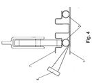
- Fig. 4 illustrates a radiator with an aluminum plate 1 welded onto copper tubes 2. Additional shaped aluminum fins 7 formed by a corrugated sheet are welded onto the copper pipes. The aluminum fins are thinner than the plate 1 and have been welded on the copper pipes before the final configuration of the water channels, and increase the power of the radiator by increasing the surface heating the air.
- Figs. 5a and 5b illustrate a radiator made of an aluminum plate 1 welded onto copper tubes 2 and aluminum fins 3 shaped and welded onto the aluminum plate and extending transversely thereto.
- Fig 5b. also illustrates how the pulse laser is applied to weld the fins 7 to the plate 1.
- Figs. 6a and 6b illustrate a relatively high radiator, for example 2 meters, with a curved form that is made from an aluminum plate 1 welded onto vertical copper tubes 2. The assembly of the tube and plate is then formed into its curved shape. The horizontal distribution pipes 6 are welded last.
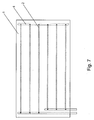
- Fig. 7 illustrates radiator of long length with horizontally configured pipes 2, forming together with distribution pipes 6 a serpentine flow path with a hot water inlet and outlet on the same side.
Landscapes
- Engineering & Computer Science (AREA)
- Physics & Mathematics (AREA)
- Mechanical Engineering (AREA)
- Optics & Photonics (AREA)
- Thermal Sciences (AREA)
- General Engineering & Computer Science (AREA)
- Plasma & Fusion (AREA)
- Chemical & Material Sciences (AREA)
- Combustion & Propulsion (AREA)
- Geometry (AREA)
- Heat-Exchange Devices With Radiators And Conduit Assemblies (AREA)
- Laser Beam Processing (AREA)
Abstract
Description
- The invention relates to space heating radiators, in particular to space heating radiators that comprise tubes and metal plates and heat with infrared radiation emission and with convection.
- Conventional radiators are usually formed by a pair of corrugated steel plates welded to one another. The steel plates are shaped so as to form water channels. In order to increase their capacity to transfer by convection, they often have steel fins welded on the surface panels where the water is flowing through.
- In order to form the water channels, the use of two steel plates is required, with adequate thickness, the weight and the cost are therefore significant. The distances between the water channels and their cross-section are chosen such that the temperature of the radiator is uniform, thus ensuring the highest possible heat transmission for a given size of radiator. Because the thermal conductivity of steel is relatively low, the distance between the water channels should be small. The shape of the radiators is limited by the material and the manufacturing method.
- Another type of radiator is formed of steel or copper tubes. The wall thickness of pipes is such that they can be shaped and welded. This leads to a relatively high weight in comparison to the obtained radiating surface. The appearance of this type of radiators limits their acceptance.
- The use of aluminum improves the thermal conductivity but this material is usually not used to form water channels. The difficulty to form water channels limits the wide spread use of aluminum. If aluminum plating is used, the copper or steel water tubes are usually mechanically bonded to the plate. To maintain a good heat transfer it is necessary to have large tube surface in contact with the aluminum plate. The tube surface bonded in the aluminum does however not contribute to the heating.
- Similar problems, even if the heat flow is from the plate to the water channel, are also faced in the solar energy absorber of solar thermal collectors. Ultrasonic welding is used here to attach the copper plate absorber to the copper pipes. This technology is however not suitable for welding of aluminum plates to copper tubes.
- The development of pulse laser welding allows the welding of copper tubes onto a full size plate of aluminum. The welding is achieved with a laser beam that is focused in the acute angle formed between the copper pipes and the side of the absorber plate.
- On this background, it is an object of the present invention to provide a space heating radiator that overcomes the above mentioned drawbacks. This object is achieved in accordance with
claim 1 by providing a space heating radiator comprising at least one copper or copper alloy tube for conveying a heat transport medium and one or more aluminum or aluminum alloy panels for heat transfer to the surrounding space via radiation and convection that are secured to the copper alloy tube by welds. Thus, an effective, easy to manufacture and esthetically pleasing radiator is provided. - Two or more radiators according of this type can be connected in series to form a high power radiator
- It is yet another object of the present invention to provide a method of producing a space heating radiator that overcomes the above mentioned drawbacks. This object is achieved in accordance with claim 8 by providing a method of producing a space heating radiator comprising the steps of providing at least one copper or copper alloy tube for the transport of the heating medium, providing at least one aluminum or aluminum alloy panel for heat transfer to the surrounding space via radiation and convection, temporarily securing said copper or copper alloy tube on one of the sides of said at least one aluminum or aluminum alloy panel, permanently securing said copper or copper alloy tube to one of the sides of said at least one aluminum or aluminum alloy panel by applying a laser beam that is focused in the acute angle formed between the copper or copper alloy tubing and the side of the aluminum or aluminum alloy panel.
- Further objects, features, advantages and properties of the space heating radiator and method of producing a space heating radiator according to the invention will become apparent from the detailed description.
- In the following detailed portion of the present description, the invention will be explained in more detail with reference to the exemplary embodiments shown in the drawings, in which
- Fig. 1 illustrates a side view of a radiator according to a first embodiment,
- Fig. 2 illustrates the welding step of an embodiment of the method of producing a radiator,
- Figs. 3a to 3d are different views of a radiator according to a second embodiment,
- Fig. 4 illustrates the welding step of a radiator according to a third embodiment,
- Figs. 5a and 5b illustrate fins that may be added to the radiator,
- Figs. 6a and 6b are different views of a radiator according to a fourth embodiment,
- Fig. 7 illustrates a side view of a radiator according to a fifth embodiment.
-
- Fig. 1 illustrates a first embodiment of a radiator that comprises one
tube 2 of suitable diameter to form a meander or serpentine conduit. The tube serves as a conduit for transporting the heating medium, which is usually hot water from a central heating system. A semi-hard copper tube with e.g. 10mm diameter and wall thickness 0,4 mm, is de-coiled through a forming machine to obtain a meander shape. The distance between the parallel pipes is for example 100 mm. - The copper tube ends are brazed with bronze fittings with e.g. ½" male thread, to be connected with a heating valve (not shown). The
tube 2 can be made of different types of copper alloys such as Copper tube material Cu-DHP (CW024A). - An
aluminum plate 1, e.g. 0,8mm thick, painted white on the one side, with paint having high emissivity at infrared and covered by thin protective plastic foil, is cut in suitable dimensions. The sides of theplate 1 are formed so that there are no exposed sharp edges. Theplate 1 can be made of different aluminum alloys such as Aluminum Alloy:AlMg 1. - With reference to Fig. 2 the
aluminum plate 1 is placed on horizontal flat table 3 with the painted surface facing the table. Thewater tube 2 is placed on thealuminum plate 1 and are temporarily fixed with mechanical clamps. Fig. 2 shows in section, the table 3 and the lower part of a suitable assembly 4 that presses from above on thepipe 2 to press the latter onto thealuminum plate 1. The pressure is local in the area of the welding, and the assembly 4 moves along thetube 2 as it is welded. - One or two
pulse laser beams 5 are directed, transverse to the long axis of the pipe, in the acute recess that is formed between the pipe and thealuminum plate 1. The two reflective metals, the wavelength of beam, and the conical form of the recess, lead to the absorption of the energy of the beam resulting in the formation of a weld permanently connecting the tube to the plate. To increase the productivity, a second optical system directs simultaneously a laser beam on the opposite side of the copper tube. The welding speed can be more than 20 cm per second, depending on the capacity of the power source, the frequency of pulse and the distance between the welding spots. - Figs. 3a,3b,3c and 3d illustrate a radiator that is made from
aluminum panels 1 welded onto tubes forming a serpentine conduit or flow path. Thevertical pipes 2 have a smaller diameter than thehorizontal header 3 which distributes the water in the vertical tubes. - Fig. 4 illustrates a radiator with an
aluminum plate 1 welded ontocopper tubes 2. Additional shapedaluminum fins 7 formed by a corrugated sheet are welded onto the copper pipes. The aluminum fins are thinner than theplate 1 and have been welded on the copper pipes before the final configuration of the water channels, and increase the power of the radiator by increasing the surface heating the air. - Figs. 5a and 5b illustrate a radiator made of an
aluminum plate 1 welded ontocopper tubes 2 andaluminum fins 3 shaped and welded onto the aluminum plate and extending transversely thereto. Fig 5b. also illustrates how the pulse laser is applied to weld thefins 7 to theplate 1. - Figs. 6a and 6b illustrate a relatively high radiator, for example 2 meters, with a curved form that is made from an
aluminum plate 1 welded ontovertical copper tubes 2. The assembly of the tube and plate is then formed into its curved shape. The horizontal distribution pipes 6 are welded last. - Fig. 7 illustrates radiator of long length with horizontally configured
pipes 2, forming together with distribution pipes 6 a serpentine flow path with a hot water inlet and outlet on the same side. - Thus, while the preferred embodiments of the devices and methods have been described in reference to the environment in which they were developed, they are merely illustrative of the principles of the inventions. Other embodiments and configurations may be devised without departing from the scope of the appended claims.
Claims (13)
- A space heating radiator comprising at least one copper or copper alloy tube for conveying a heat transport medium and one or more aluminum or aluminum alloy panels for heat transfer to the surrounding space via radiation and convection that are secured to the copper alloy tube by welds.
- A radiator according to claim 1, wherein the welds are laser beam welds.
- A radiator according to the claim 1, wherein the tube has a serpentine form, said serpentine form preferably being created by an assembly of vertical tubes with horizontal tubes welded between them.
- A radiator according to the claim 1, wherein the tube has the form of a meandering conduit.
- A radiator according to claim 1, further comprising aluminum fins secured to said tubes or to said panels by welds for increasing heat transfer by convection.
- A radiator according to claim 5, wherein the welds securing the fins are laser welds.
- An assembly of two or more radiators according to claim 1, connected in series to form a high power radiator.
- A method of producing a space heating radiator, comprising the steps of:providing at least one copper or copper alloy tube for the transport of the heating medium;providing at least one aluminum or aluminum alloy panel for heat transfer to the surrounding space via radiation and convection;temporarily securing said copper or copper alloy tube on one of the sides of said at least one aluminum or aluminum alloy panel;permanently securing said copper or copper alloy tube to one of the sides of said at least one aluminum or aluminum alloy panel by applying a laser beam that is focused in the acute angle formed between the copper or copper alloy tubing and the side of the aluminum or aluminum alloy panel.
- A method according to claim 8, wherein two laser beams are applied simultaneously on opposite sides of the tube.
- A method according to claim 8, wherein the laser beam is a pulsed laser.
- A method according to claim 8, in which the tube or tubes are be shaped before the step of permanently securing the tube to the plate.
- A method according to claim 8, in which the tube is permanently secured to the panel by a series of welding spots.
- A method according claim 8, further comprising the step of providing the final surface treatment to the panel before the welding step.
Applications Claiming Priority (2)
| Application Number | Priority Date | Filing Date | Title |
|---|---|---|---|
| GR2004100001 | 2004-01-02 | ||
| GR20040100001A GR1004729B (en) | 2004-01-02 | 2004-01-02 | Heating body with copper water pipe structure welded to aluminium sheets by means of laser beam bundle |
Publications (2)
| Publication Number | Publication Date |
|---|---|
| EP1550834A1 true EP1550834A1 (en) | 2005-07-06 |
| EP1550834B1 EP1550834B1 (en) | 2016-05-18 |
Family
ID=33561657
Family Applications (1)
| Application Number | Title | Priority Date | Filing Date |
|---|---|---|---|
| EP04028835.9A Expired - Lifetime EP1550834B1 (en) | 2004-01-02 | 2004-12-06 | Radiant panel |
Country Status (3)
| Country | Link |
|---|---|
| US (1) | US20050145680A1 (en) |
| EP (1) | EP1550834B1 (en) |
| GR (1) | GR1004729B (en) |
Cited By (12)
| Publication number | Priority date | Publication date | Assignee | Title |
|---|---|---|---|---|
| WO2006065195A1 (en) * | 2004-12-13 | 2006-06-22 | Sunstrip Ab | A method for manufacturing a heat-exchanger and a system for performing the method |
| EP1828700A1 (en) * | 2004-12-22 | 2007-09-05 | TI Group Automotive Systems Limited | A heat exchanger |
| EP1906113A1 (en) * | 2006-09-29 | 2008-04-02 | Vestel Beyaz Esya Sanayi Ve Ticaret A.S. | Production method of evaporator |
| NL1034696C2 (en) * | 2007-11-14 | 2009-05-15 | Allco Equipment Bvba | Oven for powder coating of products, has heating unit positioned within housing along standing wall and including hot air pipe, where heating unit creates flow of heated air through hot air pipe into burner |
| GB2472655A (en) * | 2009-08-15 | 2011-02-16 | Colin Robson | A panel to assist in radiating heat around a bed |
| WO2011009785A3 (en) * | 2009-07-21 | 2011-04-07 | BSH Bosch und Siemens Hausgeräte GmbH | Heat exchanger and method for producing the same |
| WO2011120667A1 (en) | 2010-03-30 | 2011-10-06 | Li-Tec Battery Gmbh | Contact element for diverters of electrochemical cells |
| GB2482697A (en) * | 2010-08-11 | 2012-02-15 | Clive Johnson | Metallic heating panel including a serpentine conduit |
| EP2418448A1 (en) * | 2010-08-09 | 2012-02-15 | BSH Electrodomésticos España, S.A. | Heat exchanger, household appliance, method for manufacturing a heat exchanger, and method for installing a heat exchanger |
| WO2012020373A1 (en) * | 2010-08-09 | 2012-02-16 | BSH Bosch und Siemens Hausgeräte GmbH | Heat exchanger, household appliance, method for manufacturing a heat exchanger, and method for installing a heat exchanger |
| CN105522277A (en) * | 2014-09-28 | 2016-04-27 | 大族激光科技产业集团股份有限公司 | Fully-automatic interactive type laser welding equipment for solar heat collector plate core |
| EP2762787A3 (en) * | 2013-01-31 | 2016-09-21 | Barcol-Air AG | Air conditioning element for a heating and cooling ceiling |
Families Citing this family (7)
| Publication number | Priority date | Publication date | Assignee | Title |
|---|---|---|---|---|
| US8474446B1 (en) * | 2010-03-23 | 2013-07-02 | Caleffi S.P.A. | Solar collector |
| GB2484300B (en) * | 2010-10-05 | 2016-08-10 | Frenger Systems Ltd | Improvements in or relating to heat exchangers for air conditioning systems |
| JP6087936B2 (en) * | 2011-10-11 | 2017-03-01 | サボ−ソーラー オサケユイチア | Method of manufacturing direct flow aluminum absorber for solar collector, direct flow aluminum absorber, and solar collector |
| CN109845052B (en) * | 2016-08-31 | 2022-01-11 | 恩耐公司 | Laser cooling system |
| CN107062600A (en) * | 2017-05-15 | 2017-08-18 | 北京航空航天大学 | A kind of alkali metal air chamber low noise heating means based on laser |
| CN112119546B (en) | 2018-03-12 | 2024-03-26 | 恩耐公司 | Fiber laser with variable coiled fiber |
| TR2024012937A2 (en) * | 2024-09-27 | 2024-10-21 | Elba Basincli Doekuem Sanayii Anonim Sirketi | A PANEL RADIATOR AND ITS PRODUCTION METHOD |
Citations (9)
| Publication number | Priority date | Publication date | Assignee | Title |
|---|---|---|---|---|
| US2386889A (en) * | 1940-08-02 | 1945-10-16 | Outboard Marine & Mfg Co | Coil assembly |
| US4224499A (en) * | 1978-10-20 | 1980-09-23 | General Electric Company | Laser welding aluminum to copper |
| EP0222176A1 (en) * | 1985-11-15 | 1987-05-20 | ARMCO S.p.A. | Heat exchanger, particularly evaporator, and method of manufacturing same |
| EP0423500A2 (en) * | 1989-10-16 | 1991-04-24 | Helmut Lingemann GmbH & Co. | Method of fabricating a flat condenser for a refrigeration machine, in particular for a household refrigerator, and the flat condenser thereof |
| DE19635843A1 (en) * | 1996-09-04 | 1998-03-05 | Oppermann Willi Friedrich | Laser pipe-welding installation |
| WO1998035191A1 (en) * | 1997-02-10 | 1998-08-13 | Raco S.P.A | Evaporator making method, such evaporator and use thereof |
| US6300591B1 (en) * | 2000-03-23 | 2001-10-09 | Sandia Corporation | Method for laser welding a fin and a tube |
| EP1362662A1 (en) * | 2002-05-08 | 2003-11-19 | Lasag Ag | Laser welding head and laser welding apparatus |
| GB2397642A (en) * | 2002-12-16 | 2004-07-28 | Philip Andrew Kennedy | Heat transfer element |
Family Cites Families (12)
| Publication number | Priority date | Publication date | Assignee | Title |
|---|---|---|---|---|
| US1841379A (en) * | 1928-01-26 | 1932-01-19 | George H Phelps | Radiator |
| US2226291A (en) * | 1939-07-28 | 1940-12-24 | Gen Electric | Heat exchanger |
| US2598279A (en) * | 1949-08-24 | 1952-05-27 | George N Mckibbin | Panel-type heater |
| US2731245A (en) * | 1951-09-14 | 1956-01-17 | Kaiser Aluminium Chem Corp | Finned conduit and method of attaching fins to conduit |
| US2790628A (en) * | 1953-04-29 | 1957-04-30 | Utica Drop Forge & Tool Corp | Fabricated fin tube heat exchanger |
| DE1926187A1 (en) * | 1969-05-22 | 1970-11-26 | Schoell Dr Ing Guenter | Heat exchange element made of materials with low thermal conductivity and strength |
| JPS6216894A (en) * | 1985-07-17 | 1987-01-26 | Toyota Motor Corp | Padding method for aluminum base metal |
| DE3807476A1 (en) * | 1988-03-08 | 1989-09-28 | Messerschmitt Boelkow Blohm | MACHINING DEVICE FOR WORKPIECES |
| US5423498A (en) * | 1993-04-27 | 1995-06-13 | E-Systems, Inc. | Modular liquid skin heat exchanger |
| US5283584A (en) * | 1993-05-06 | 1994-02-01 | The United States Of America As Represented By The Secrtary Of The Army | High power photon triggered ultra-wideband RF radiator with opposite apertures |
| DE19721657A1 (en) * | 1997-05-23 | 1998-12-10 | Nova Solar Gmbh | Heat exchanger for solar collectors for heating and cooling systems |
| US6173886B1 (en) * | 1999-05-24 | 2001-01-16 | The University Of Tennessee Research Corportion | Method for joining dissimilar metals or alloys |
-
2004
- 2004-01-02 GR GR20040100001A patent/GR1004729B/en unknown
- 2004-12-03 US US11/004,444 patent/US20050145680A1/en not_active Abandoned
- 2004-12-06 EP EP04028835.9A patent/EP1550834B1/en not_active Expired - Lifetime
Patent Citations (9)
| Publication number | Priority date | Publication date | Assignee | Title |
|---|---|---|---|---|
| US2386889A (en) * | 1940-08-02 | 1945-10-16 | Outboard Marine & Mfg Co | Coil assembly |
| US4224499A (en) * | 1978-10-20 | 1980-09-23 | General Electric Company | Laser welding aluminum to copper |
| EP0222176A1 (en) * | 1985-11-15 | 1987-05-20 | ARMCO S.p.A. | Heat exchanger, particularly evaporator, and method of manufacturing same |
| EP0423500A2 (en) * | 1989-10-16 | 1991-04-24 | Helmut Lingemann GmbH & Co. | Method of fabricating a flat condenser for a refrigeration machine, in particular for a household refrigerator, and the flat condenser thereof |
| DE19635843A1 (en) * | 1996-09-04 | 1998-03-05 | Oppermann Willi Friedrich | Laser pipe-welding installation |
| WO1998035191A1 (en) * | 1997-02-10 | 1998-08-13 | Raco S.P.A | Evaporator making method, such evaporator and use thereof |
| US6300591B1 (en) * | 2000-03-23 | 2001-10-09 | Sandia Corporation | Method for laser welding a fin and a tube |
| EP1362662A1 (en) * | 2002-05-08 | 2003-11-19 | Lasag Ag | Laser welding head and laser welding apparatus |
| GB2397642A (en) * | 2002-12-16 | 2004-07-28 | Philip Andrew Kennedy | Heat transfer element |
Cited By (16)
| Publication number | Priority date | Publication date | Assignee | Title |
|---|---|---|---|---|
| WO2006065195A1 (en) * | 2004-12-13 | 2006-06-22 | Sunstrip Ab | A method for manufacturing a heat-exchanger and a system for performing the method |
| EP1828700A1 (en) * | 2004-12-22 | 2007-09-05 | TI Group Automotive Systems Limited | A heat exchanger |
| EP1906113A1 (en) * | 2006-09-29 | 2008-04-02 | Vestel Beyaz Esya Sanayi Ve Ticaret A.S. | Production method of evaporator |
| NL1034696C2 (en) * | 2007-11-14 | 2009-05-15 | Allco Equipment Bvba | Oven for powder coating of products, has heating unit positioned within housing along standing wall and including hot air pipe, where heating unit creates flow of heated air through hot air pipe into burner |
| WO2011009785A3 (en) * | 2009-07-21 | 2011-04-07 | BSH Bosch und Siemens Hausgeräte GmbH | Heat exchanger and method for producing the same |
| GB2472655A (en) * | 2009-08-15 | 2011-02-16 | Colin Robson | A panel to assist in radiating heat around a bed |
| CN102821905A (en) * | 2010-03-30 | 2012-12-12 | 锂电池科技有限公司 | Contact element for diverters of electrochemical cells |
| WO2011120667A1 (en) | 2010-03-30 | 2011-10-06 | Li-Tec Battery Gmbh | Contact element for diverters of electrochemical cells |
| DE102010013351A1 (en) | 2010-03-30 | 2011-12-15 | Li-Tec Battery Gmbh | Contact element for arresters of galvanic cells |
| ES2399133R1 (en) * | 2010-08-09 | 2013-08-08 | Bsh Electrodomesticos Espana | HEAT EXCHANGER, DOMESTIC APPLIANCE, METHOD FOR MANUFACTURING A HEAT EXCHANGER, AND METHOD FOR INSTALLING A HEAT EXCHANGER |
| WO2012020373A1 (en) * | 2010-08-09 | 2012-02-16 | BSH Bosch und Siemens Hausgeräte GmbH | Heat exchanger, household appliance, method for manufacturing a heat exchanger, and method for installing a heat exchanger |
| EP2418448A1 (en) * | 2010-08-09 | 2012-02-15 | BSH Electrodomésticos España, S.A. | Heat exchanger, household appliance, method for manufacturing a heat exchanger, and method for installing a heat exchanger |
| GB2482697A (en) * | 2010-08-11 | 2012-02-15 | Clive Johnson | Metallic heating panel including a serpentine conduit |
| EP2762787A3 (en) * | 2013-01-31 | 2016-09-21 | Barcol-Air AG | Air conditioning element for a heating and cooling ceiling |
| CN105522277A (en) * | 2014-09-28 | 2016-04-27 | 大族激光科技产业集团股份有限公司 | Fully-automatic interactive type laser welding equipment for solar heat collector plate core |
| CN105522277B (en) * | 2014-09-28 | 2017-12-15 | 大族激光科技产业集团股份有限公司 | Full-automatic interactive plate core of solar heat-collecting laser welding apparatus |
Also Published As
| Publication number | Publication date |
|---|---|
| US20050145680A1 (en) | 2005-07-07 |
| GR1004729B (en) | 2004-11-22 |
| EP1550834B1 (en) | 2016-05-18 |
Similar Documents
| Publication | Publication Date | Title |
|---|---|---|
| EP1550834B1 (en) | Radiant panel | |
| US20140231057A1 (en) | Heat exchanger incorporating integral flow directors | |
| CN103575140A (en) | Compact type aluminum heat exchanger with welding pipe for power electronic equipment and battery cooling | |
| JPH0118353B2 (en) | ||
| RS52962B (en) | MODULAR SOLAR COLLECTOR | |
| JP2011202910A (en) | Sunlight heat collecting apparatus | |
| CN100453255C (en) | Method for producing a heat exchanger and device for carrying out said method | |
| US20080190414A1 (en) | Absorber for a Thermal Solar Collector and Method for the Production of Said Absorber | |
| EP1906113B1 (en) | Production method of evaporator | |
| US4558735A (en) | Heat exchanger having a metal baffle plate secured to a steel member | |
| AU2004213524B2 (en) | Absorber for a thermal collector of a solar system and method for the production thereof | |
| CN201000298Y (en) | Liquid medium cold/heat radiation plate | |
| TWI712767B (en) | Plate heat exchanger for solar heating | |
| CN201539984U (en) | Solar energy flat plate collector | |
| GB2397642A (en) | Heat transfer element | |
| CN103925724A (en) | Solar heat collection board high in heat transfer efficiency | |
| CN2757035Y (en) | Heat transfer core strip of solar energy collector | |
| RU2450217C2 (en) | Heat receiving panel of solar collector | |
| GB1565092A (en) | Making heat exchangers | |
| CN1573255A (en) | Heat transferring core bar of solar energy collector | |
| EP2096376A2 (en) | Extruded metal absorber for solar collector | |
| JPS5828901B2 (en) | solar collector | |
| JPS58224261A (en) | Manufacture of solar heat collecting plate | |
| CN102947651B (en) | Solar collector, solar collector device and solar collector | |
| JP2005283092A (en) | Solar heat collecting and radiating device, and manufacturing method therefor |
Legal Events
| Date | Code | Title | Description |
|---|---|---|---|
| PUAI | Public reference made under article 153(3) epc to a published international application that has entered the european phase |
Free format text: ORIGINAL CODE: 0009012 |
|
| 17P | Request for examination filed |
Effective date: 20050418 |
|
| AK | Designated contracting states |
Kind code of ref document: A1 Designated state(s): AT BE BG CH CY CZ DE DK EE ES FI FR GB GR HU IE IS IT LI LT LU MC NL PL PT RO SE SI SK TR |
|
| AX | Request for extension of the european patent |
Extension state: AL BA HR LV MK YU |
|
| AKX | Designation fees paid |
Designated state(s): AT BE BG CH CY CZ DE DK EE ES FI FR GB GR HU IE IS IT LI LT LU MC NL PL PT RO SE SI SK TR |
|
| REG | Reference to a national code |
Ref country code: DE Ref legal event code: R079 Ref document number: 602004049315 Country of ref document: DE Free format text: PREVIOUS MAIN CLASS: F28F0001220000 Ipc: F24D0003140000 |
|
| GRAP | Despatch of communication of intention to grant a patent |
Free format text: ORIGINAL CODE: EPIDOSNIGR1 |
|
| RIC1 | Information provided on ipc code assigned before grant |
Ipc: B23K 26/32 20140101ALI20151207BHEP Ipc: B23K 103/08 20060101ALI20151207BHEP Ipc: F28F 1/22 20060101ALI20151207BHEP Ipc: F28F 21/08 20060101ALI20151207BHEP Ipc: B23K 103/22 20060101ALI20151207BHEP Ipc: B23K 103/12 20060101ALI20151207BHEP Ipc: F28D 1/047 20060101ALI20151207BHEP Ipc: F24D 3/14 20060101AFI20151207BHEP Ipc: B23K 103/10 20060101ALI20151207BHEP Ipc: B23K 26/323 20140101ALI20151207BHEP Ipc: B23K 26/242 20140101ALI20151207BHEP Ipc: B23K 101/14 20060101ALI20151207BHEP |
|
| INTG | Intention to grant announced |
Effective date: 20151223 |
|
| GRAS | Grant fee paid |
Free format text: ORIGINAL CODE: EPIDOSNIGR3 |
|
| GRAA | (expected) grant |
Free format text: ORIGINAL CODE: 0009210 |
|
| RAP1 | Party data changed (applicant data changed or rights of an application transferred) |
Owner name: PRIME LASER TECHNOLOGY SA |
|
| RIN1 | Information on inventor provided before grant (corrected) |
Inventor name: TRAVASSAROS, CONSTANTINE |
|
| AK | Designated contracting states |
Kind code of ref document: B1 Designated state(s): AT BE BG CH CY CZ DE DK EE ES FI FR GB GR HU IE IS IT LI LT LU MC NL PL PT RO SE SI SK TR |
|
| REG | Reference to a national code |
Ref country code: GB Ref legal event code: FG4D |
|
| REG | Reference to a national code |
Ref country code: CH Ref legal event code: EP |
|
| REG | Reference to a national code |
Ref country code: IE Ref legal event code: FG4D Ref country code: AT Ref legal event code: REF Ref document number: 800834 Country of ref document: AT Kind code of ref document: T Effective date: 20160615 |
|
| REG | Reference to a national code |
Ref country code: DE Ref legal event code: R096 Ref document number: 602004049315 Country of ref document: DE |
|
| REG | Reference to a national code |
Ref country code: CH Ref legal event code: NV Representative=s name: MICHELI AND CIE SA, CH |
|
| REG | Reference to a national code |
Ref country code: NL Ref legal event code: MP Effective date: 20160518 |
|
| REG | Reference to a national code |
Ref country code: LT Ref legal event code: MG4D |
|
| PG25 | Lapsed in a contracting state [announced via postgrant information from national office to epo] |
Ref country code: NL Free format text: LAPSE BECAUSE OF FAILURE TO SUBMIT A TRANSLATION OF THE DESCRIPTION OR TO PAY THE FEE WITHIN THE PRESCRIBED TIME-LIMIT Effective date: 20160518 Ref country code: LT Free format text: LAPSE BECAUSE OF FAILURE TO SUBMIT A TRANSLATION OF THE DESCRIPTION OR TO PAY THE FEE WITHIN THE PRESCRIBED TIME-LIMIT Effective date: 20160518 Ref country code: FI Free format text: LAPSE BECAUSE OF FAILURE TO SUBMIT A TRANSLATION OF THE DESCRIPTION OR TO PAY THE FEE WITHIN THE PRESCRIBED TIME-LIMIT Effective date: 20160518 |
|
| REG | Reference to a national code |
Ref country code: FR Ref legal event code: PLFP Year of fee payment: 13 |
|
| REG | Reference to a national code |
Ref country code: AT Ref legal event code: MK05 Ref document number: 800834 Country of ref document: AT Kind code of ref document: T Effective date: 20160518 |
|
| PG25 | Lapsed in a contracting state [announced via postgrant information from national office to epo] |
Ref country code: GR Free format text: LAPSE BECAUSE OF FAILURE TO SUBMIT A TRANSLATION OF THE DESCRIPTION OR TO PAY THE FEE WITHIN THE PRESCRIBED TIME-LIMIT Effective date: 20160819 Ref country code: SE Free format text: LAPSE BECAUSE OF FAILURE TO SUBMIT A TRANSLATION OF THE DESCRIPTION OR TO PAY THE FEE WITHIN THE PRESCRIBED TIME-LIMIT Effective date: 20160518 Ref country code: ES Free format text: LAPSE BECAUSE OF FAILURE TO SUBMIT A TRANSLATION OF THE DESCRIPTION OR TO PAY THE FEE WITHIN THE PRESCRIBED TIME-LIMIT Effective date: 20160518 Ref country code: PT Free format text: LAPSE BECAUSE OF FAILURE TO SUBMIT A TRANSLATION OF THE DESCRIPTION OR TO PAY THE FEE WITHIN THE PRESCRIBED TIME-LIMIT Effective date: 20160919 |
|
| PG25 | Lapsed in a contracting state [announced via postgrant information from national office to epo] |
Ref country code: EE Free format text: LAPSE BECAUSE OF FAILURE TO SUBMIT A TRANSLATION OF THE DESCRIPTION OR TO PAY THE FEE WITHIN THE PRESCRIBED TIME-LIMIT Effective date: 20160518 Ref country code: RO Free format text: LAPSE BECAUSE OF FAILURE TO SUBMIT A TRANSLATION OF THE DESCRIPTION OR TO PAY THE FEE WITHIN THE PRESCRIBED TIME-LIMIT Effective date: 20160518 Ref country code: SK Free format text: LAPSE BECAUSE OF FAILURE TO SUBMIT A TRANSLATION OF THE DESCRIPTION OR TO PAY THE FEE WITHIN THE PRESCRIBED TIME-LIMIT Effective date: 20160518 Ref country code: DK Free format text: LAPSE BECAUSE OF FAILURE TO SUBMIT A TRANSLATION OF THE DESCRIPTION OR TO PAY THE FEE WITHIN THE PRESCRIBED TIME-LIMIT Effective date: 20160518 Ref country code: CZ Free format text: LAPSE BECAUSE OF FAILURE TO SUBMIT A TRANSLATION OF THE DESCRIPTION OR TO PAY THE FEE WITHIN THE PRESCRIBED TIME-LIMIT Effective date: 20160518 |
|
| REG | Reference to a national code |
Ref country code: DE Ref legal event code: R097 Ref document number: 602004049315 Country of ref document: DE |
|
| PG25 | Lapsed in a contracting state [announced via postgrant information from national office to epo] |
Ref country code: PL Free format text: LAPSE BECAUSE OF FAILURE TO SUBMIT A TRANSLATION OF THE DESCRIPTION OR TO PAY THE FEE WITHIN THE PRESCRIBED TIME-LIMIT Effective date: 20160518 Ref country code: AT Free format text: LAPSE BECAUSE OF FAILURE TO SUBMIT A TRANSLATION OF THE DESCRIPTION OR TO PAY THE FEE WITHIN THE PRESCRIBED TIME-LIMIT Effective date: 20160518 Ref country code: BE Free format text: LAPSE BECAUSE OF FAILURE TO SUBMIT A TRANSLATION OF THE DESCRIPTION OR TO PAY THE FEE WITHIN THE PRESCRIBED TIME-LIMIT Effective date: 20160518 |
|
| PLBE | No opposition filed within time limit |
Free format text: ORIGINAL CODE: 0009261 |
|
| STAA | Information on the status of an ep patent application or granted ep patent |
Free format text: STATUS: NO OPPOSITION FILED WITHIN TIME LIMIT |
|
| 26N | No opposition filed |
Effective date: 20170221 |
|
| PG25 | Lapsed in a contracting state [announced via postgrant information from national office to epo] |
Ref country code: SI Free format text: LAPSE BECAUSE OF FAILURE TO SUBMIT A TRANSLATION OF THE DESCRIPTION OR TO PAY THE FEE WITHIN THE PRESCRIBED TIME-LIMIT Effective date: 20160518 |
|
| PG25 | Lapsed in a contracting state [announced via postgrant information from national office to epo] |
Ref country code: MC Free format text: LAPSE BECAUSE OF FAILURE TO SUBMIT A TRANSLATION OF THE DESCRIPTION OR TO PAY THE FEE WITHIN THE PRESCRIBED TIME-LIMIT Effective date: 20160518 |
|
| REG | Reference to a national code |
Ref country code: IE Ref legal event code: MM4A |
|
| PG25 | Lapsed in a contracting state [announced via postgrant information from national office to epo] |
Ref country code: IT Free format text: LAPSE BECAUSE OF NON-PAYMENT OF DUE FEES Effective date: 20161206 Ref country code: LU Free format text: LAPSE BECAUSE OF NON-PAYMENT OF DUE FEES Effective date: 20161206 |
|
| PG25 | Lapsed in a contracting state [announced via postgrant information from national office to epo] |
Ref country code: IE Free format text: LAPSE BECAUSE OF NON-PAYMENT OF DUE FEES Effective date: 20161206 |
|
| REG | Reference to a national code |
Ref country code: FR Ref legal event code: PLFP Year of fee payment: 14 |
|
| PG25 | Lapsed in a contracting state [announced via postgrant information from national office to epo] |
Ref country code: CY Free format text: LAPSE BECAUSE OF FAILURE TO SUBMIT A TRANSLATION OF THE DESCRIPTION OR TO PAY THE FEE WITHIN THE PRESCRIBED TIME-LIMIT Effective date: 20160518 Ref country code: HU Free format text: LAPSE BECAUSE OF FAILURE TO SUBMIT A TRANSLATION OF THE DESCRIPTION OR TO PAY THE FEE WITHIN THE PRESCRIBED TIME-LIMIT; INVALID AB INITIO Effective date: 20041206 |
|
| PG25 | Lapsed in a contracting state [announced via postgrant information from national office to epo] |
Ref country code: TR Free format text: LAPSE BECAUSE OF FAILURE TO SUBMIT A TRANSLATION OF THE DESCRIPTION OR TO PAY THE FEE WITHIN THE PRESCRIBED TIME-LIMIT Effective date: 20160518 Ref country code: IS Free format text: LAPSE BECAUSE OF FAILURE TO SUBMIT A TRANSLATION OF THE DESCRIPTION OR TO PAY THE FEE WITHIN THE PRESCRIBED TIME-LIMIT Effective date: 20160518 |
|
| PG25 | Lapsed in a contracting state [announced via postgrant information from national office to epo] |
Ref country code: BG Free format text: LAPSE BECAUSE OF FAILURE TO SUBMIT A TRANSLATION OF THE DESCRIPTION OR TO PAY THE FEE WITHIN THE PRESCRIBED TIME-LIMIT Effective date: 20160518 |
|
| PGFP | Annual fee paid to national office [announced via postgrant information from national office to epo] |
Ref country code: GB Payment date: 20231031 Year of fee payment: 20 |
|
| PGFP | Annual fee paid to national office [announced via postgrant information from national office to epo] |
Ref country code: FR Payment date: 20231031 Year of fee payment: 20 Ref country code: DE Payment date: 20231025 Year of fee payment: 20 |
|
| PGFP | Annual fee paid to national office [announced via postgrant information from national office to epo] |
Ref country code: CH Payment date: 20240101 Year of fee payment: 20 |
|
| REG | Reference to a national code |
Ref country code: DE Ref legal event code: R071 Ref document number: 602004049315 Country of ref document: DE |
|
| REG | Reference to a national code |
Ref country code: CH Ref legal event code: PL |
|
| REG | Reference to a national code |
Ref country code: GB Ref legal event code: PE20 Expiry date: 20241205 |
|
| PG25 | Lapsed in a contracting state [announced via postgrant information from national office to epo] |
Ref country code: GB Free format text: LAPSE BECAUSE OF EXPIRATION OF PROTECTION Effective date: 20241205 |
|
| PG25 | Lapsed in a contracting state [announced via postgrant information from national office to epo] |
Ref country code: GB Free format text: LAPSE BECAUSE OF EXPIRATION OF PROTECTION Effective date: 20241205 |