EP1550790B1 - Injektorvorrichtung eines Kontrastmittels - Google Patents
Injektorvorrichtung eines Kontrastmittels Download PDFInfo
- Publication number
- EP1550790B1 EP1550790B1 EP03293353A EP03293353A EP1550790B1 EP 1550790 B1 EP1550790 B1 EP 1550790B1 EP 03293353 A EP03293353 A EP 03293353A EP 03293353 A EP03293353 A EP 03293353A EP 1550790 B1 EP1550790 B1 EP 1550790B1
- Authority
- EP
- European Patent Office
- Prior art keywords
- tool
- injector
- tracer
- tools
- group
- Prior art date
- Legal status (The legal status is an assumption and is not a legal conclusion. Google has not performed a legal analysis and makes no representation as to the accuracy of the status listed.)
- Expired - Lifetime
Links
Images


Classifications
-
- E—FIXED CONSTRUCTIONS
- E21—EARTH OR ROCK DRILLING; MINING
- E21B—EARTH OR ROCK DRILLING; OBTAINING OIL, GAS, WATER, SOLUBLE OR MELTABLE MATERIALS OR A SLURRY OF MINERALS FROM WELLS
- E21B47/00—Survey of boreholes or wells
- E21B47/10—Locating fluid leaks, intrusions or movements
- E21B47/11—Locating fluid leaks, intrusions or movements using tracers; using radioactivity
-
- E—FIXED CONSTRUCTIONS
- E21—EARTH OR ROCK DRILLING; MINING
- E21B—EARTH OR ROCK DRILLING; OBTAINING OIL, GAS, WATER, SOLUBLE OR MELTABLE MATERIALS OR A SLURRY OF MINERALS FROM WELLS
- E21B47/00—Survey of boreholes or wells
- E21B47/12—Means for transmitting measuring-signals or control signals from the well to the surface, or from the surface to the well, e.g. for logging while drilling
Definitions
- the invention relates generally to downhole injection of one or more tracers or marker materials in a well.
- the fluid may be oil, water, gas or a combination, even a mixture, of all three. It is generally desirable to monitor the velocities of the fluids actually down the well itself rather than merely when they reach the surface.
- a first method involves the use of a mechanical "spinner»: a wireline-supported tool carrying a small propeller- (or turbine-) driven dynamo is placed in a flowing fluid so that the propeller is turned around by it, and the dynamo's output indicates the velocity of the flowing fluid.
- the first method provides satisfactory results in borehole sections that are vertical, but not in sections which are horizontal.
- a horizontal section may indeed comprise several layers, e.g. an oil layer above a water layer.
- a second method involves an injector/detector tool that injects a small amount of tracer e.g., a detectable chemical or a radioactive substance, at a first location and detects the injected tracer at a second location.
- tracer e.g., a detectable chemical or a radioactive substance
- the flow velocity is calculated by a simple distance over time calculation.
- An example of injector/detector tool is the Tracer Injector tool of Schlumberger which is described in U.S. Pat. Nos. 4,166,215 and 4,166,216.
- the U.S. patent 6,125,934 describes an injector tool adapted for a horizontal section.
- the injector tool For a determined tracer intended to be ejected into a corresponding layer, the injector tool comprises an ejection port that is oriented such that the determined tracer may be ejected directly into the corresponding layer. Hence an oil miscible tracer is injected into an oil layer and a water miscible tracer is injected into a water layer.
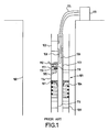
- FIG. 1 illustrates a typical injector/detector tool known from prior art.
- An injector tool 101 ejects a tracer into a borehole 102 at a first location (not shown in FIG. 1), and a detector tool 103 detects the tracer at a second location (not shown in FIG. 1).
- the ejection of the tracer is commanded via a command wire 106 that controls from a surface system 111 located at the surface a solenoid valve 105 of the injector tool.
- the solenoid valve 105 When the switch is on, the solenoid valve 105 is open and a relatively constant force acting on a piston 107 due to a spring 104 expels an amount of the tracer through a thin tube 112.
- FIG. 1 illustrates a system as it is being used in a vertical well.
- a system may also be used in a horizontal well.
- it may further comprise an ejection port that is judicially oriented to aim a determined layer.
- a dedicated wire 108 transmits an analog signal to activate the detector tool 103, thus allowing to detect the tracer.
- the detector tool transmits results to the surface system 111 via a results wire 115.
- the electrical wires (106, 108, 115) are located within a central chamber 113 so as to be protected from any liquid.
- the central chamber 113 may also contain one or more additional wires that are used for a communicating between the surface system 111 and one or more additional devices, e.g. a logging device 109.
- the tracer is directly ejected from a reservoir 114.
- the quantity of tracer that is discharged into the borehole 102 is determined by a duration of the opening of the solenoid valve 105, the duration being controlled at surface.
- it is not possible to insure that the quantity of tracer corresponding to the duration has effectively been ejected.
- the quantity of tracer that is periodically discharged into the borehole space is determined by a size of a syringe filled with the tracer before ejection.
- the tracer may be stored in a reservoir that communicates with the syringe so as to provide a regular filling of the syringe.
- a Hall Effect sensor may detect the end of stroke of the piston so as to confirm that the quantity of tracer has been ejected.
- the injector tool When a piece of the injector tool has to be replaced, e.g., the reservoir 114, the injector tool needs to be completely stripped out. It is indeed necessary to cut electrical wires located in the central chamber 113 to remove the piece.
- the electro-valve 105 comprises a solenoid coil 117 communicating with the command wire 106, and a solenoid seat 118 through which the tracer is expelled.
- the solenoid coil 117 is used to control a movement of a plunger 119 that allows the tracer to be expelled.
- the solenoid seat 118 is replaced, the solenoid coil also needs to be removed.
- the invention provides an injector tool as defined in the appended claims 1 to 6 and a tool system for monitoring a flow of liquid within a borehole as defined in the appended claims 7 to 13.
- FIG. 1 illustrates a schematic of an injector/detector tool within a borehole from Prior Art.
- FIG. 2 illustrates an example of a tool system according to the present invention.
- FIG. 3 illustrates an example of a portion of an injector tool according to the present invention.
- FIG. 4 illustrates measuring means of an injector tool according to a preferred embodiment of the present invention.
- FIG. 5 illustrates an example of an algorithm to be executed by an electronic card of a tool system according to the present invention.
- FIG. 6 illustrates an example of a portion of an injector tool according to the present invention.
- the ejector/detector tool from prior art encloses a dedicated wire to insure a synchronization between the injector tool and the detector tool at the ejecting of the tracer.
- An analog signal activates the detector for a possible detecting of the tracer. If intermediate tools are located between the injector tool and the detector tool, the dedicated wire has to run through all the intermediate tools, which adds an additional cabling to an intermediate cabling of the intermediate tools. Hence, the injector tool may not be easily set anywhere.
- a water producing zone above the hole may generate a reverse flow.
- a possible way to detect the presence of the hole is to measure a velocity of the reverse flow in the borehole.
- the reverse flow may also be caused by a recirculation of water in a horizontal well. In both cases, a production rate of the well is affected.
- the reverse flow may be monitored by ejecting a tracer at a first location with an injector tool and by providing a detector tool at a second location, the second location being located deeper within the borehole than the first location. In a case of a lateral hole, the second location is located further from a main well than the first location.
- the quantity of tracer that is periodically discharged into the borehole is predetermined. It may occur that the predetermined quantity is too small to allow a proper detection of the tracer. Or, on the contrary, the predetermined quantity may be so high that a recharging of the reservoir is frequently required. There is a need for a system in which the ejected quantity of tracer may be commanded and changed from the surface.
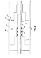
- FIG. 2 illustrates an example of a tool system for monitoring a flow of liquid within a borehole according to the invention.
- a plurality of tools (201, 203, 204, 205, 207) is disposed on a longitudinal axis of a tool system 212 within a borehole 202. In this example, the tools are assembled to form a tube.
- the plurality of tools (201, 203, 204, 205, 207) comprises at least a first injector tool 201 for ejecting in the borehole 202 a tracer and a detector tool 203 to detect the ejected tracer.
- a standard digital bus 206 traverses longitudinally at least a portion of each tool of the plurality of tools (201, 203, 204, 205, 207). The standard digital bus 206 allows a communication between each tool of the plurality of tools (201, 203,204,205,207).
- a control tool 207 manages data exchanges through the standard digital bus 206.
- the control tool 207 in addition communicates with a surface system 211 through a surface bus 208.
- the system according to the invention allows to dispose the injector tool at a greater distance from the detector tool than the systems from prior art. The measurements of the flow velocity may thus be more accurate.
- the standard digital bus 206 allows to insure the synchronization.
- an ejection counter (not represented) is activated at the ejecting of the tracer.
- the activating of the ejection counter allows to activate at least the detector tool 203.
- the ejection counter is incremented at an acquisition frequency that is independent from a communication frequency of the communication between the plurality of tools (201, 203, 204, 205, 207).
- the acquisition frequency may have a relatively high value, e.g. 15 kHz.
- the communication frequency at which the plurality of tools (201, 203, 204, 205, 207) communicates may be smaller than the acquisition frequency and may vary with time. Typically, the communication frequency may be smaller than 5 Hz.
- the ejection counter hence allows to evaluate a time duration between the ejecting and the detecting of the tracer with a relatively high precision.
- a value of the injection counter may be read to evaluate the time duration between the ejecting and the detecting.
- the synchronization may be performed by broadcasting a single ejection command to both the first injector tool 201 and the detector tool 203.
- the standard digital bus 206 may also be used to allow a communication with a second injector tool 205 located opposite the detector tool 203 when seen from the first injector 201, so as to allow to detect a possible reverse flow in the borehole 202.
- the plurality of tools may also comprise a third injector tool 204 distinct from the first injector tool 201, the third injector tool 204 being located on the same side of but more distant from the detector tool 203.
- the third injector tool 204 may eject the same type of tracer as the first injector tool 201. Because of a greater distance between the third injector tool 204 and the detector tool 203, and because the detector tool 203 detects tracer ejected at different locations, a better accuracy of the measuring of the flow velocity is thus provided.
- the third injector tool 204 may also eject a second tracer different from the tracer ejected by the first injector tool 201.
- the second tracer may be an oil tracer, intended to coalesce with an oil phase
- the tracer ejected by the first injector tool 201 may be a water tracer intended to coalesce with a water or brine phase.
- the flow velocities of both the oil phase and the water phase are measured using a single detector tool.
- the well is horizontal; the first injector tool and the third injector tool may comprise an ejection port.
- the ejection port of the first injection tool may be oriented downward so as to inject a water or brine tracer, and the ejection port of the third ejection tool may be oriented upward so as to eject an oil tracer.
- the system according to the invention allows a multiple injector tools - single detector tool configuration, unlike the systems from prior art.
- the detector tools is not required to manage several analog signals from several dedicated wires coming from several ejector tools as is the case with the systems from prior art.
- the invention allows more than a single injector tool for a single detector.
- the system according to the invention provides compatibility between the injector tools and any other downhole tool that uses the standard digital bus to communicate.
- the first injector tool may be able to communicate with an orientating tool.
- the orientating tool may for example comprise a relative bearing measuring tool.
- the orientating tool may also comprise absolute angle measuring means, thus providing a reliable measurement of an orientation of the ejection port.
- the orientating tool may comprise a probe that is able to evaluate a nature of the determined layer (oil, water). Hence such an orientating tool provides various measurements that may be crucial for monitoring correctly a flow of liquid of the determined layer.
- the standard digital bus allows the first injector tool and any other tool to communicate with the orientating tool, and to supply both tools with power.
- the tools of the plurality of tools may comprise a standard connector.
- the standard connector of the first injector tool allows a first group of electrical wires corresponding to the standard digital bus along the first injector tool to be removably connected to a second group of electrical wires.
- the second group of electrical wires corresponds to the standard digital bus along a distinct tool of the plurality of tools, i.e. a tool that is able to communicate using the standard digital bus.
- the standard connector hence allows to replace one of the tools of the plurality of tools by another, e.g. the first injector tool and the detector tool may be interchanged so as to detect a possible reverse flow.
- the first injector tools comprises a dedicated connector, and the replacing of one tool by an other is thus more complex.
- the standard digital bus may for example be a Production Service Platform bus (PSP).
- PSP Production Service Platform bus
- the PSP bus comprises two power wires dedicated to power transportation, and two signal wires dedicated to signal transportation.
- the standard digital bus may also be any digital bus that allows a communicating between devices.
- the plurality of tools comprises at least the first injector tool and the detector tool.
- the plurality of tools of the present invention may comprise other devices such as logging devices that also communicate using the standard digital bus.
- the system according to the invention may also comprise some extra tools that communicate using a dedicated wire, or using a second bus distinct from the standard digital bus.
- FIG. 3 illustrates an example of an injector tool for ejecting a tracer in a tool system for monitoring a flow of liquid within a borehole according to the invention.
- the injector tool 303 comprises measuring means 310 to measure an ejected quantity of the ejected tracer.
- the measuring means 310 may, as represented in FIG. 3, be located within the injector tool 303. As the tracer 302 stored into a reservoir 304 is typically expelled by a displacement of a piston 307, the measuring means 310 may measure a displacement of the piston 307 relative to a body 311 of the injector tool 303.
- An electro-valve 305 controls an opening 312 through which the tracer may be ejected from the injector tool 303.
- actuating means e.g. a spring (not represented on FIG. 3) move the piston 307 when the electro-valve 305 opens the opening 312 and the tracer is ejected.
- the measuring means 310 allow to measure the ejected quantity of tracer.
- the piston 307 may comprise three magnetic rings 301 that are mounted thereon so as to have a same movement as the piston 307.
- Hall Effect switches 309 mounted on the body 311 detect a displacement of the magnetic rings 301.
- Such measuring means that involve the Hall Effect may be designed to avoid any contact between the tracer and themselves. Hence it is possible to use corrosive tracers.
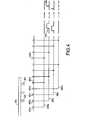
- FIG. 4 illustrates a preferred embodiment of measuring means according to the present invention.
- the Hall Effect switches 401 are organized in four independent arrays. Each array of switches may be longitudinally disposed with a determined azimuthal angle, even if the Hall Effect switches 401 are represented on a same axis on FIG. 4. Each array is tied to a corresponding wire (403a, 403b, 403c, 403d). A signal 405 on a determined wire 403b is generated by a passage of a magnetic ring 402 close to one of the Hall effect switches 401b belonging to the array corresponding to the determined wire 403b.
- the three magnetic rings 402 located on an extension 404 of a piston are separated from each other by a distance that is 33% higher than a space between two Hall Effect switches, so as to provide a measurement that is three times more accurate than with a single magnetic ring.
- the signal 405 may be processed so as to generate a pulse 406 at its rising edge. By observing the pulses corresponding to the four electrical wires, it is possible to measure a relative displacement of the piston relative to the Hall Effect switches.
- an absolute displacement of a piston relative to a body may be measured.
- FIG. 5 illustrates an example of an algorithm to be executed by an electronic card downhole.
- the electronic card may be part of a tool system comprising the injector tool and a detector tool, the detector tool allowing to detect the ejected tracer.
- a desired number N corresponding to a value of a desired quantity of tracer is received in box 501 from a surface system.
- the ejecting of the tracer then starts at box 502. In a preferred embodiment, the starting is performed by opening an electro-valve.
- the opening of the electro-valve allows a displacing of the piston actuated for example by a spring.
- the measuring means provide a measurement of the ejected quantity of tracer, which is proportional to a displacement of the piston.
- a measured number T2 corresponding to the displacement of the piston, and hence, to the measured ejected quantity of tracer is regularly read at box 503.
- the measured number T2 is compared in box 505 to the desired number N. If the measured number T2 is smaller than the desired number N, i.e. the measured ejected quantity of tracer is smaller than the value of the desired quantity, then a new value of the measured number T2 is read (in box 503) from the measuring means, thus repeating an ejection cycle.
- the ejected quantity of tracer is substantially equal to the desired quantity.
- the ejection may hence be interrupted at box 506: the electro-valve is closed.
- This example algorithm enables to eject a desired quantity of tracer, wherein the value of the desired quantity is received from the surface system at each ejection operation.
- the value of the desired quantity of tracer may thus be changed, which allows to increase the quantity of ejected tracer for a proper detection of the tracer at the detector tool, or on the contrary, to reduce the quantity and save some tracer.
- the injector tool also allows to measure a duration of the ejecting.
- the electrical card may comprise a frame counter FRCT, as illustrated in the algorithm of FIG. 5.
- the frame counter FRCT is initialized.
- the frame counter FRCT is incremented in box 504.
- the value of the frame counter FRCT is a function of the duration of the ejecting; it is transmitted at box 507 to the surface system. Knowing the duration of the injecting allows to model a behavior of the ejected tracer within the borehole, and hence to predict a shape of a measured signal at the detector tool. A time at which the ejected tracer is detected may thus be measured more accurately.
- the measuring means may be any mean to detect a displacement of a piston relative to a body, and, more generally, any means that provide an evaluating of an ejected quantity of the tracer.
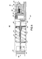
- FIG. 6 illustrates an example of a portion of an injector tool intended to eject a tracer for monitoring a flow of liquid 609 in a well according to the invention.
- the injector tool 601 comprises a first group of hydraulic parts (603; 610; 616) intended to be in contact with the tracer, and a second group of electrical elements (604; 605; 617).
- the electrical elements (604; 605; 617) may be any element able to conduct electricity for power or signal transportation, e.g. an electronic card (not represented), Hall Effect sensors 617, etc.
- the hydraulic parts (603; 610; 616) may be any piece that may be in contact with the tracer, e.g. a reservoir 603, a piston 616, etc.
- the hydraulic parts (603; 610; 616) of the first group may be accessed and replaced during a maintenance operation.
- the electrical elements (604; 605; 617) of the second group remain protected during the maintenance operation.
- the hydraulic parts (603; 610; 616) of the first group may be directly accessed without cutting electrical wires 605 as in prior art. Furthermore, in a case of a rig site maintenance operation, the electrical elements (604; 605; 617) of the second group remain isolated from contamination by an external fluid in the well even during the maintenance operations, so that they do not need to be replaced. There is hence no need to touch any electrical element (604; 605; 617) of the second group, either for accessing one of the hydraulic parts (603; 610; 616), or for replacing them after a deterioration due to the maintenance operation.
- the injector tool comprises an electro-valve 606 that, when opened, allows to expel the tracer.
- the electro-valve 606 discloses a solenoid seat 610 through which the tracer is expelled, the solenoid seat 610 belonging to the first group.
- the electro-valve also discloses an electrical portion, e.g. a solenoid coil 604 that is relied to a command wire 619.
- the solenoid coil 604 is used to control a movement of a plunger 611 and belongs to the second group.
- the tracer stored in the reservoir 603 passes through a tube (not represented) and is kept in the solenoid seat 610. The movement of the plunger 611 allows the tracer to be expelled.
- the electro-valve 606 is oriented so that the solenoid seat 610 is at a peripheral position compared to the solenoid coil 604, i.e. the solenoid seat 610 may be accessed without removing the solenoid coil 604.
- the electro-valve 606 may disclose a high pressure barrier 608 that isolates the solenoid coil 604 from the solenoid seat 610.
- the solenoid coil 604 remains protected when the solenoid seat 610 is replaced.
- the electrical wires 605 of the injector tool belong to the second group and remain protected during a replacing of the reservoir 603.
- the electrical wires are located within a chamber 614.
- the Hall Effect sensors 617 allowing a measurement of a quantity of ejected tracer are also located within the chamber 614.
- a connector 620 allows to connect the electrical wires with another electronic system, e.g. the electronic card (not represented) of the injector tool 601, or electrical wires of a second tool (not represented).
- the connector 620 may comprise a first portion 612 that is mounted on an outside tube 621, and a second portion 613 that is mounted on an inside tube, e.g. the chamber 614.
- the first portion 612 of the connector 620 is removed.
- the second portion 613 of the connector continues to protect the electrical wires 605 and the Hall Effect sensors 617 from the liquid 609 within the well.
- a spring 615, the piston 616 and the reservoir 603 may hence slide along the chamber 614 so as to be replaced.
- the invention allows to remove and replace the hydraulic parts much more easily than in prior art. Hence corrosive tracers may be used.
Landscapes
- Geology (AREA)
- Physics & Mathematics (AREA)
- Life Sciences & Earth Sciences (AREA)
- Engineering & Computer Science (AREA)
- Mining & Mineral Resources (AREA)
- Environmental & Geological Engineering (AREA)
- Geophysics (AREA)
- Fluid Mechanics (AREA)
- Geochemistry & Mineralogy (AREA)
- General Life Sciences & Earth Sciences (AREA)
- Geophysics And Detection Of Objects (AREA)
- Indicating Or Recording The Presence, Absence, Or Direction Of Movement (AREA)
- Infusion, Injection, And Reservoir Apparatuses (AREA)
- Apparatus For Radiation Diagnosis (AREA)
- Medicines Containing Antibodies Or Antigens For Use As Internal Diagnostic Agents (AREA)
Claims (13)
- Injektorwerkzeug (303) zum Ausstoßen eines Indikators in einem System zum Überwachen einer Flüssigkeitsströmung in einem Bohrloch, wobei das Injektorwerkzeug (303) umfasst:Messmittel (310) zum Messen einer ausgestoßenen Menge des ausgestoßenen Indikators;einen Körper (311) ;einen Kolben (307) zum Austreiben des Indikators;wobei die Messmittel (310) eine Verlagerung des Kolbens (307) relativ zu dem Körper (311) messen; unddadurch gekennzeichnet, dass die Messmittel (310) umfassen:wenigstens einen magnetischen Ring (301), der an dem Kolben (307) angebracht ist;mehrere Hall-Effekt-Schalter (309), die an dem Körper (311) angebracht sind.
- Injektorwerkzeug nach Anspruch 1, bei dem
drei magnetische Ringe (402) an dem Kolben angebracht sind;
die Hall-Effekt-Schalter (401) in vier unabhängigen Anordnungen organisiert sind; und
die Hall-Effekt-Schalter (401), die zu einer bestimmten Anordnung gehören, an einem einzigen, bestimmten Draht (403a, 403b, 403c, 403d) befestigt sind. - Injektorwerkzeug (303) nach Anspruch 1 oder 2, das ferner umfasst:einen Vorratsbehälter (304), in dem der Indikator aufbewahrt wird;eine Öffnung (312), durch die der Indikator aus dem Injektorwerkzeug (303) ausgestoßen werden kann;ein Elektroventil (305) zum Steuern der Öffnung (312);Betätigungsmittel zum Bewegen des Kolbens (307) in der Weise, dass sich der Kolben (307) bewegt, wenn das Elektroventil (305) die Öffnung (304) öffnet und der Indikator ausgestoßen wird.
- Injektorwerkzeug (601) nach einem der Ansprüche 1 bis 3, wobei das Injektorwerkzeug (601) umfasst:eine erste Gruppe von hydraulischen Teilen (603, 610, 616), die mit dem Indikator in Kontakt gelangen sollen ;eine zweite Gruppe von elektrischen Elementen (604, 605, 617);wobei während eines Wartungsvorgangs auf die hydraulischen Teile der ersten Gruppe zugegriffen werden kann und die hydraulischen Teile der ersten Gruppe ersetzt werden können; undwobei die elektrischen Elemente der zweiten Gruppe während des Wartungsvorgangs geschützt bleiben.
- Injektorwerkzeug (601) nach Anspruch 4, das ferner ein Elektroventil umfasst, wobei das Elektroventil (606) umfasst:einen elektrischen Abschnitt, der zu der zweiten Gruppe gehört;einen Elektromagnetsitz (610), der zu der ersten Gruppe gehört;eine Hochdrucksperre (608) zum Isolieren des elektrischen Abschnitts des Elektroventils (606) von dem Elektromagnetsitz (610);wobei das Elektroventil (606) in dem Injektorwerkzeug (601) in der Weise angebracht ist, dass auf den Elektromagnetsitz (610) zugegriffen werden kann, ohne den elektrischen Abschnitt zu entfernen.
- Injektorwerkzeug (601) nach Anspruch 4, das ferner umfasst:elektrische Drähte (605), die zu der zweiten Gruppe gehören;einen Verbinder (620), der ermöglicht, die elektrischen Elemente der zweiten Gruppe mit anderen elektrischen Elementen eines hiervon verschiedenen Werkzeugs zu verbinden, wobei der Verbinder einen ersten Abschnitt (612) und einen zweiten Abschnitt (613) aufweist, wobei der erste Abschnitt (612) während des Wartungsvorgangs entfernt werden kann und wobei der zweite Abschnitt (613) während des Wartungsvorgangs die elektrischen Drähte (605) weiterhin schützt.
- Werkzeugsystem (212) zum Überwachen einer Flüssigkeitsströmung in einem Bohrloch (202), das umfasst:mehrere Werkzeuge (201, 203, 204, 205, 207), die auf einer Längsachse des Werkzeugsystems (212) angeordnet sind, wobei die mehreren Werkzeuge (201, 203, 204, 205, 207) wenigstens ein erstes Injektorwerkzeug (201) nach einem der Ansprüche 1 bis 6 zum Ausstoßen eines Indikators in das Bohrloch (202) und ein Detektorwerkzeug (203) zum Erfassen des ausgestoßenen Indikators umfassen;einen digitalen Standardbus (206), der wenigstens durch einen Abschnitt jedes Werkzeugs der mehreren Werkzeuge (201, 203, 204, 205, 207) verläuft, wobei der digitale Standardbus (206) eine Kommunikation zwischen jedem der mehreren Werkzeuge (201, 203, 204, 205, 207) ermöglicht.
- Werkzeugsystem (212) nach Anspruch 7, bei dem die mehreren Werkzeuge (201, 203, 204, 205, 207) ein Steuerwerkzeug (207) umfassen, um einen jeweiligen Datenaustausch über den digitalen Standardbus (206) zu managen.
- Werkzeugsystem (212) nach Anspruch 7 oder 8, bei dem die mehreren Werkzeuge (201, 203, 204, 205, 207) ein zweites Injektorwerkzeug (205) nach einem der Ansprüche 1 bis 6 umfassen, wobei sich das zweite Injektorwerkzeug (205) im Vergleich zu dem ersten Injektorwerkzeug (201) auf einer gegenüberliegenden Seite des Detektorwerkzeugs (203) des Werkzeugsystems (212) befindet, um so die Erfassung einer möglichen Rückwärtsströmung im Bohrloch (202) zu ermöglichen.
- Werkzeugsystem (212) nach einem der Ansprüche 7 bis 9, bei dem die mehreren Werkzeuge (201, 203, 204, 205, 207) außerdem ein drittes Injektorwerkzeug (204) nach einem der Ansprüche 1 bis 6, das von dem ersten Injektorwerkzeug (201) verschieden ist, umfassen, wobei sich das dritte Injektorwerkzeug (204) auf derselben Seite des Detektorwerkzeugs (203) in dem Werkzeugsystem (212) wie das erste Injektorwerkzeug (201) befindet.
- Werkzeugsystem nach einem der Ansprüche 7 bis 10, bei dem das Bohrloch eine im Wesentlichen horizontale Längsrichtung besitzt;
die mehreren Werkzeuge außerdem ein Orientierungswerkzeug umfassen, um eine Orientierung wenigstens eines Ausstoßanschlusses des ersten Injektorwerkzeugs zu messen. - Werkzeugsystem nach einem der Ansprüche 7 bis 11, bei dem das erste Injektorwerkzeug eine erste Gruppe von elektrischen Drähten, die dem digitalen Standardbus entsprechen, und wenigstens einen Standardverbinder, der eine lösbare Verbindung der ersten Gruppe von elektrischen Drähten mit einer zweiten Gruppe von elektrischen Drähten, die dem digitalen Standardbus in einem von den mehreren Werkzeugen verschiedenen Werkzeug entsprechen, ermöglicht, umfasst.
- Werkzeugsystem nach Anspruch 12, bei dem sowohl die erste Gruppe von elektrischen Drähten als auch die zweite Gruppe von elektrischen Drähten zwei Leistungsversorgungsdrähte, die dem Leistungstransport gewidmet sind, und zwei Signaldrähte, die dem Signaltransport gewidmet sind, umfasst.
Priority Applications (6)
| Application Number | Priority Date | Filing Date | Title |
|---|---|---|---|
| AT03293353T ATE355442T1 (de) | 2003-12-31 | 2003-12-31 | Injektorvorrichtung eines kontrastmittels |
| DE60312192T DE60312192D1 (de) | 2003-12-31 | 2003-12-31 | Injektorvorrichtung eines Kontrastmittels |
| EP03293353A EP1550790B1 (de) | 2003-12-31 | 2003-12-31 | Injektorvorrichtung eines Kontrastmittels |
| US10/596,814 US7628203B2 (en) | 2003-12-31 | 2004-12-01 | Tracer injector tool for well investigation |
| PCT/EP2004/013681 WO2005064115A1 (en) | 2003-12-31 | 2004-12-01 | Tracer injector tool |
| US12/608,477 US8118094B2 (en) | 2003-12-31 | 2009-10-29 | Tracer injector tool for well investigation |
Applications Claiming Priority (1)
| Application Number | Priority Date | Filing Date | Title |
|---|---|---|---|
| EP03293353A EP1550790B1 (de) | 2003-12-31 | 2003-12-31 | Injektorvorrichtung eines Kontrastmittels |
Publications (2)
| Publication Number | Publication Date |
|---|---|
| EP1550790A1 EP1550790A1 (de) | 2005-07-06 |
| EP1550790B1 true EP1550790B1 (de) | 2007-02-28 |
Family
ID=34560243
Family Applications (1)
| Application Number | Title | Priority Date | Filing Date |
|---|---|---|---|
| EP03293353A Expired - Lifetime EP1550790B1 (de) | 2003-12-31 | 2003-12-31 | Injektorvorrichtung eines Kontrastmittels |
Country Status (5)
| Country | Link |
|---|---|
| US (2) | US7628203B2 (de) |
| EP (1) | EP1550790B1 (de) |
| AT (1) | ATE355442T1 (de) |
| DE (1) | DE60312192D1 (de) |
| WO (1) | WO2005064115A1 (de) |
Families Citing this family (7)
| Publication number | Priority date | Publication date | Assignee | Title |
|---|---|---|---|---|
| US20090151939A1 (en) * | 2007-12-13 | 2009-06-18 | Schlumberger Technology Corporation | Surface tagging system with wired tubulars |
| US8172007B2 (en) * | 2007-12-13 | 2012-05-08 | Intelliserv, LLC. | System and method of monitoring flow in a wellbore |
| US8967252B2 (en) * | 2009-05-11 | 2015-03-03 | The Trustees Of Columbia University In The City Of New York | Systems, methods, and devices for tagging carbon dioxide stored in geological formations |
| WO2011060195A2 (en) | 2009-11-11 | 2011-05-19 | Nuvo Research Inc. | Topical eutectic formulation |
| US9863243B1 (en) | 2015-04-28 | 2018-01-09 | National Technology & Engineering Solutions Of Sandia, Llc | Ruggedized downhole tool for real-time measurements and uses thereof |
| CN105467152B (zh) * | 2015-12-21 | 2018-06-29 | 山东科技大学 | 用于地下承压水示踪实验的示踪剂投放装置 |
| US11326440B2 (en) | 2019-09-18 | 2022-05-10 | Exxonmobil Upstream Research Company | Instrumented couplings |
Family Cites Families (15)
| Publication number | Priority date | Publication date | Assignee | Title |
|---|---|---|---|---|
| US2453456A (en) * | 1945-03-07 | 1948-11-09 | Phillips Petroleum Co | Instrument for measuring water flow in wells |
| US3156818A (en) * | 1960-07-25 | 1964-11-10 | Socony Mobil Oil Co Inc | Radioactive fluid flow measuring apparatus with means for injecting a marker material between the source and detector |
| US3343408A (en) * | 1963-05-13 | 1967-09-26 | Well Reconnaissance Inc | Tracer injector and detector |
| US3692106A (en) * | 1971-04-12 | 1972-09-19 | Edward R Basham | Apparatus for ejecting fluid in a borehole |
| FR2379694A1 (fr) * | 1977-02-03 | 1978-09-01 | Schlumberger Prospection | Systeme de transmission de donnees pour puits de forage |
| US4149411A (en) * | 1977-02-14 | 1979-04-17 | Umbaugh Electronics | Milk production meter |
| US4166216A (en) | 1977-09-23 | 1979-08-28 | Schlumberger Technology Corporation | Methods and apparatus for determining dynamic flow characteristics of production fluids in a well bore |
| US4166215A (en) | 1977-09-23 | 1979-08-28 | Schlumberger Technology Corporation | Methods and apparatus for determining dynamic flow characteristics of production fluids in a well bore |
| US4861986A (en) * | 1988-03-07 | 1989-08-29 | Halliburton Logging Services, Inc. | Tracer injection method |
| US6017198A (en) * | 1996-02-28 | 2000-01-25 | Traylor; Leland B | Submersible well pumping system |
| GB9610574D0 (en) | 1996-05-20 | 1996-07-31 | Schlumberger Ltd | Downhole tool |
| AU743159B2 (en) | 1997-04-25 | 2002-01-17 | Petroleum Research And Development N.V. | Phased perforating guns |
| US6715550B2 (en) * | 2000-01-24 | 2004-04-06 | Shell Oil Company | Controllable gas-lift well and valve |
| US6840316B2 (en) * | 2000-01-24 | 2005-01-11 | Shell Oil Company | Tracker injection in a production well |
| US7193525B2 (en) * | 2003-10-21 | 2007-03-20 | Schlumberger Technology Corporation | Methods and apparatus for downhole inter-tool communication |
-
2003
- 2003-12-31 AT AT03293353T patent/ATE355442T1/de not_active IP Right Cessation
- 2003-12-31 DE DE60312192T patent/DE60312192D1/de not_active Expired - Lifetime
- 2003-12-31 EP EP03293353A patent/EP1550790B1/de not_active Expired - Lifetime
-
2004
- 2004-12-01 US US10/596,814 patent/US7628203B2/en not_active Expired - Fee Related
- 2004-12-01 WO PCT/EP2004/013681 patent/WO2005064115A1/en not_active Ceased
-
2009
- 2009-10-29 US US12/608,477 patent/US8118094B2/en not_active Expired - Fee Related
Also Published As
| Publication number | Publication date |
|---|---|
| US20100044036A1 (en) | 2010-02-25 |
| US20070144737A1 (en) | 2007-06-28 |
| EP1550790A1 (de) | 2005-07-06 |
| US8118094B2 (en) | 2012-02-21 |
| ATE355442T1 (de) | 2006-03-15 |
| WO2005064115A1 (en) | 2005-07-14 |
| DE60312192D1 (de) | 2007-04-12 |
| US7628203B2 (en) | 2009-12-08 |
Similar Documents
| Publication | Publication Date | Title |
|---|---|---|
| US8118094B2 (en) | Tracer injector tool for well investigation | |
| US12378875B2 (en) | Targeted tracer injection with online sensor | |
| CA2407452C (en) | Apparatus and method for locating joints in coiled tubing operations | |
| CA2442475C (en) | Smart cementing systems | |
| US6305467B1 (en) | Wireless coiled tubing joint locator | |
| US6253842B1 (en) | Wireless coiled tubing joint locator | |
| US10865637B2 (en) | Real time radioactive | |
| EP2823134B1 (de) | Verfahren zur kommunikation mit messgeräten | |
| CN104302871A (zh) | 用于监测井下工具的方法和设备 | |
| US20140340990A1 (en) | Method And Assembly For Determining Landing Of Logging Tools In A Wellbore | |
| WO2015069281A1 (en) | Energy harvesting from a downhole jar | |
| US4771635A (en) | Fluid injector for tracer element well borehole injection | |
| WO2001042622A1 (en) | Method and device for transferring data | |
| NO20160744A1 (en) | Systems and Methods for Real-Time Evaluation of Coiled Tubing Matrix Acidizing | |
| EP0646215A1 (de) | Verfahren und vorrichtung für druck-, volumen und temperaturmessungen und zur charakterisierung von untertägigen formationen | |
| CN103758514A (zh) | 一种用于井壁取芯仪的岩芯区分及储存结构 | |
| CA2649193C (en) | Measurement while drilling tool and method | |
| US2989631A (en) | Tracer injector and detector | |
| WO2016061179A1 (en) | Smart lower end | |
| AU2013386825B2 (en) | Fluid flow during landing of logging tools in bottom hole assembly | |
| WO2016193502A1 (en) | Steam quality measuring device | |
| CA2593440C (en) | Apparatus and method for locating joints in coiled tubing operations | |
| CN202391415U (zh) | 凡尔压力计 | |
| CA1128923A (en) | Measuring while drilling tool |
Legal Events
| Date | Code | Title | Description |
|---|---|---|---|
| PUAI | Public reference made under article 153(3) epc to a published international application that has entered the european phase |
Free format text: ORIGINAL CODE: 0009012 |
|
| AK | Designated contracting states |
Kind code of ref document: A1 Designated state(s): AT BE BG CH CY CZ DE DK EE ES FI FR GB GR HU IE IT LI LU MC NL PT RO SE SI SK TR |
|
| AX | Request for extension of the european patent |
Extension state: AL LT LV MK |
|
| 17P | Request for examination filed |
Effective date: 20051216 |
|
| AKX | Designation fees paid |
Designated state(s): AT BE BG CH CY CZ DE DK EE ES FI FR GB GR HU IE IT LI LU MC NL PT RO SE SI SK TR |
|
| GRAP | Despatch of communication of intention to grant a patent |
Free format text: ORIGINAL CODE: EPIDOSNIGR1 |
|
| GRAS | Grant fee paid |
Free format text: ORIGINAL CODE: EPIDOSNIGR3 |
|
| GRAA | (expected) grant |
Free format text: ORIGINAL CODE: 0009210 |
|
| AK | Designated contracting states |
Kind code of ref document: B1 Designated state(s): AT BE BG CH CY CZ DE DK EE ES FI FR GB GR HU IE IT LI LU MC NL PT RO SE SI SK TR |
|
| PG25 | Lapsed in a contracting state [announced via postgrant information from national office to epo] |
Ref country code: BE Free format text: LAPSE BECAUSE OF FAILURE TO SUBMIT A TRANSLATION OF THE DESCRIPTION OR TO PAY THE FEE WITHIN THE PRESCRIBED TIME-LIMIT Effective date: 20070228 Ref country code: AT Free format text: LAPSE BECAUSE OF FAILURE TO SUBMIT A TRANSLATION OF THE DESCRIPTION OR TO PAY THE FEE WITHIN THE PRESCRIBED TIME-LIMIT Effective date: 20070228 Ref country code: SI Free format text: LAPSE BECAUSE OF FAILURE TO SUBMIT A TRANSLATION OF THE DESCRIPTION OR TO PAY THE FEE WITHIN THE PRESCRIBED TIME-LIMIT Effective date: 20070228 Ref country code: NL Free format text: LAPSE BECAUSE OF FAILURE TO SUBMIT A TRANSLATION OF THE DESCRIPTION OR TO PAY THE FEE WITHIN THE PRESCRIBED TIME-LIMIT Effective date: 20070228 Ref country code: FI Free format text: LAPSE BECAUSE OF FAILURE TO SUBMIT A TRANSLATION OF THE DESCRIPTION OR TO PAY THE FEE WITHIN THE PRESCRIBED TIME-LIMIT Effective date: 20070228 Ref country code: DK Free format text: LAPSE BECAUSE OF FAILURE TO SUBMIT A TRANSLATION OF THE DESCRIPTION OR TO PAY THE FEE WITHIN THE PRESCRIBED TIME-LIMIT Effective date: 20070228 Ref country code: CH Free format text: LAPSE BECAUSE OF FAILURE TO SUBMIT A TRANSLATION OF THE DESCRIPTION OR TO PAY THE FEE WITHIN THE PRESCRIBED TIME-LIMIT Effective date: 20070228 Ref country code: LI Free format text: LAPSE BECAUSE OF FAILURE TO SUBMIT A TRANSLATION OF THE DESCRIPTION OR TO PAY THE FEE WITHIN THE PRESCRIBED TIME-LIMIT Effective date: 20070228 |
|
| REG | Reference to a national code |
Ref country code: GB Ref legal event code: FG4D |
|
| REG | Reference to a national code |
Ref country code: CH Ref legal event code: EP |
|
| REF | Corresponds to: |
Ref document number: 60312192 Country of ref document: DE Date of ref document: 20070412 Kind code of ref document: P |
|
| REG | Reference to a national code |
Ref country code: IE Ref legal event code: FG4D |
|
| PG25 | Lapsed in a contracting state [announced via postgrant information from national office to epo] |
Ref country code: BG Free format text: LAPSE BECAUSE OF EXPIRATION OF PROTECTION Effective date: 20070529 |
|
| PG25 | Lapsed in a contracting state [announced via postgrant information from national office to epo] |
Ref country code: SE Free format text: LAPSE BECAUSE OF FAILURE TO SUBMIT A TRANSLATION OF THE DESCRIPTION OR TO PAY THE FEE WITHIN THE PRESCRIBED TIME-LIMIT Effective date: 20070531 |
|
| PG25 | Lapsed in a contracting state [announced via postgrant information from national office to epo] |
Ref country code: ES Free format text: LAPSE BECAUSE OF FAILURE TO SUBMIT A TRANSLATION OF THE DESCRIPTION OR TO PAY THE FEE WITHIN THE PRESCRIBED TIME-LIMIT Effective date: 20070608 |
|
| PG25 | Lapsed in a contracting state [announced via postgrant information from national office to epo] |
Ref country code: PT Free format text: LAPSE BECAUSE OF FAILURE TO SUBMIT A TRANSLATION OF THE DESCRIPTION OR TO PAY THE FEE WITHIN THE PRESCRIBED TIME-LIMIT Effective date: 20070730 |
|
| NLV1 | Nl: lapsed or annulled due to failure to fulfill the requirements of art. 29p and 29m of the patents act | ||
| REG | Reference to a national code |
Ref country code: CH Ref legal event code: PL |
|
| ET | Fr: translation filed | ||
| PG25 | Lapsed in a contracting state [announced via postgrant information from national office to epo] |
Ref country code: SK Free format text: LAPSE BECAUSE OF FAILURE TO SUBMIT A TRANSLATION OF THE DESCRIPTION OR TO PAY THE FEE WITHIN THE PRESCRIBED TIME-LIMIT Effective date: 20070228 |
|
| PG25 | Lapsed in a contracting state [announced via postgrant information from national office to epo] |
Ref country code: RO Free format text: LAPSE BECAUSE OF FAILURE TO SUBMIT A TRANSLATION OF THE DESCRIPTION OR TO PAY THE FEE WITHIN THE PRESCRIBED TIME-LIMIT Effective date: 20070228 Ref country code: CZ Free format text: LAPSE BECAUSE OF FAILURE TO SUBMIT A TRANSLATION OF THE DESCRIPTION OR TO PAY THE FEE WITHIN THE PRESCRIBED TIME-LIMIT Effective date: 20070228 |
|
| PLBE | No opposition filed within time limit |
Free format text: ORIGINAL CODE: 0009261 |
|
| STAA | Information on the status of an ep patent application or granted ep patent |
Free format text: STATUS: NO OPPOSITION FILED WITHIN TIME LIMIT |
|
| PG25 | Lapsed in a contracting state [announced via postgrant information from national office to epo] |
Ref country code: DE Free format text: LAPSE BECAUSE OF FAILURE TO SUBMIT A TRANSLATION OF THE DESCRIPTION OR TO PAY THE FEE WITHIN THE PRESCRIBED TIME-LIMIT Effective date: 20070530 |
|
| 26N | No opposition filed |
Effective date: 20071129 |
|
| PG25 | Lapsed in a contracting state [announced via postgrant information from national office to epo] |
Ref country code: IT Free format text: LAPSE BECAUSE OF FAILURE TO SUBMIT A TRANSLATION OF THE DESCRIPTION OR TO PAY THE FEE WITHIN THE PRESCRIBED TIME-LIMIT Effective date: 20070228 Ref country code: GR Free format text: LAPSE BECAUSE OF FAILURE TO SUBMIT A TRANSLATION OF THE DESCRIPTION OR TO PAY THE FEE WITHIN THE PRESCRIBED TIME-LIMIT Effective date: 20070529 |
|
| PG25 | Lapsed in a contracting state [announced via postgrant information from national office to epo] |
Ref country code: MC Free format text: LAPSE BECAUSE OF NON-PAYMENT OF DUE FEES Effective date: 20071231 |
|
| PG25 | Lapsed in a contracting state [announced via postgrant information from national office to epo] |
Ref country code: IE Free format text: LAPSE BECAUSE OF NON-PAYMENT OF DUE FEES Effective date: 20071231 |
|
| PG25 | Lapsed in a contracting state [announced via postgrant information from national office to epo] |
Ref country code: EE Free format text: LAPSE BECAUSE OF FAILURE TO SUBMIT A TRANSLATION OF THE DESCRIPTION OR TO PAY THE FEE WITHIN THE PRESCRIBED TIME-LIMIT Effective date: 20070228 |
|
| PG25 | Lapsed in a contracting state [announced via postgrant information from national office to epo] |
Ref country code: CY Free format text: LAPSE BECAUSE OF FAILURE TO SUBMIT A TRANSLATION OF THE DESCRIPTION OR TO PAY THE FEE WITHIN THE PRESCRIBED TIME-LIMIT Effective date: 20070228 |
|
| PG25 | Lapsed in a contracting state [announced via postgrant information from national office to epo] |
Ref country code: LU Free format text: LAPSE BECAUSE OF NON-PAYMENT OF DUE FEES Effective date: 20071231 |
|
| PG25 | Lapsed in a contracting state [announced via postgrant information from national office to epo] |
Ref country code: TR Free format text: LAPSE BECAUSE OF FAILURE TO SUBMIT A TRANSLATION OF THE DESCRIPTION OR TO PAY THE FEE WITHIN THE PRESCRIBED TIME-LIMIT Effective date: 20070228 Ref country code: HU Free format text: LAPSE BECAUSE OF FAILURE TO SUBMIT A TRANSLATION OF THE DESCRIPTION OR TO PAY THE FEE WITHIN THE PRESCRIBED TIME-LIMIT Effective date: 20070901 |
|
| PGFP | Annual fee paid to national office [announced via postgrant information from national office to epo] |
Ref country code: FR Payment date: 20101201 Year of fee payment: 8 |
|
| REG | Reference to a national code |
Ref country code: FR Ref legal event code: ST Effective date: 20120831 |
|
| PG25 | Lapsed in a contracting state [announced via postgrant information from national office to epo] |
Ref country code: FR Free format text: LAPSE BECAUSE OF NON-PAYMENT OF DUE FEES Effective date: 20120102 |
|
| PGFP | Annual fee paid to national office [announced via postgrant information from national office to epo] |
Ref country code: GB Payment date: 20161228 Year of fee payment: 14 |
|
| GBPC | Gb: european patent ceased through non-payment of renewal fee |
Effective date: 20171231 |
|
| PG25 | Lapsed in a contracting state [announced via postgrant information from national office to epo] |
Ref country code: GB Free format text: LAPSE BECAUSE OF NON-PAYMENT OF DUE FEES Effective date: 20171231 |
|
| P01 | Opt-out of the competence of the unified patent court (upc) registered |
Effective date: 20231208 |