EP1550644B1 - Ceramic compositions useful in thermal barrier coatings having reduced thermal conductivity - Google Patents
Ceramic compositions useful in thermal barrier coatings having reduced thermal conductivity Download PDFInfo
- Publication number
- EP1550644B1 EP1550644B1 EP04256627.3A EP04256627A EP1550644B1 EP 1550644 B1 EP1550644 B1 EP 1550644B1 EP 04256627 A EP04256627 A EP 04256627A EP 1550644 B1 EP1550644 B1 EP 1550644B1
- Authority
- EP
- European Patent Office
- Prior art keywords
- thermal barrier
- mole
- composition
- thermal
- metal
- Prior art date
- Legal status (The legal status is an assumption and is not a legal conclusion. Google has not performed a legal analysis and makes no representation as to the accuracy of the status listed.)
- Expired - Lifetime
Links
- 239000012720 thermal barrier coating Substances 0.000 title claims description 68
- 239000000203 mixture Substances 0.000 title claims description 50
- 239000000919 ceramic Substances 0.000 title claims description 36
- MRELNEQAGSRDBK-UHFFFAOYSA-N lanthanum(3+);oxygen(2-) Chemical compound [O-2].[O-2].[O-2].[La+3].[La+3] MRELNEQAGSRDBK-UHFFFAOYSA-N 0.000 claims description 40
- 239000000758 substrate Substances 0.000 claims description 35
- 238000000034 method Methods 0.000 claims description 34
- MCMNRKCIXSYSNV-UHFFFAOYSA-N Zirconium dioxide Chemical compound O=[Zr]=O MCMNRKCIXSYSNV-UHFFFAOYSA-N 0.000 claims description 33
- 229910052751 metal Inorganic materials 0.000 claims description 30
- 239000002184 metal Substances 0.000 claims description 30
- 230000000087 stabilizing effect Effects 0.000 claims description 18
- RUDFQVOCFDJEEF-UHFFFAOYSA-N yttrium(III) oxide Inorganic materials [O-2].[O-2].[O-2].[Y+3].[Y+3] RUDFQVOCFDJEEF-UHFFFAOYSA-N 0.000 claims description 15
- 238000005240 physical vapour deposition Methods 0.000 claims description 13
- 239000003381 stabilizer Substances 0.000 claims description 8
- 238000000151 deposition Methods 0.000 claims description 5
- 229910044991 metal oxide Inorganic materials 0.000 description 49
- 150000004706 metal oxides Chemical class 0.000 description 49
- 238000000576 coating method Methods 0.000 description 29
- 239000007921 spray Substances 0.000 description 24
- 238000005328 electron beam physical vapour deposition Methods 0.000 description 17
- 239000011248 coating agent Substances 0.000 description 15
- 238000005245 sintering Methods 0.000 description 12
- 238000009792 diffusion process Methods 0.000 description 10
- 239000007789 gas Substances 0.000 description 9
- 229910001233 yttria-stabilized zirconia Inorganic materials 0.000 description 9
- PXHVJJICTQNCMI-UHFFFAOYSA-N Nickel Chemical compound [Ni] PXHVJJICTQNCMI-UHFFFAOYSA-N 0.000 description 8
- 239000000843 powder Substances 0.000 description 8
- 229910000951 Aluminide Inorganic materials 0.000 description 7
- 229910045601 alloy Inorganic materials 0.000 description 7
- 239000000956 alloy Substances 0.000 description 7
- 239000000463 material Substances 0.000 description 7
- 230000008569 process Effects 0.000 description 7
- CMIHHWBVHJVIGI-UHFFFAOYSA-N gadolinium(iii) oxide Chemical compound [O-2].[O-2].[O-2].[Gd+3].[Gd+3] CMIHHWBVHJVIGI-UHFFFAOYSA-N 0.000 description 6
- -1 yttria) Chemical class 0.000 description 6
- 238000007792 addition Methods 0.000 description 5
- 238000005229 chemical vapour deposition Methods 0.000 description 5
- 230000007547 defect Effects 0.000 description 5
- 230000000694 effects Effects 0.000 description 5
- 230000007246 mechanism Effects 0.000 description 5
- 239000002245 particle Substances 0.000 description 5
- 238000005204 segregation Methods 0.000 description 5
- XEEYBQQBJWHFJM-UHFFFAOYSA-N Iron Chemical compound [Fe] XEEYBQQBJWHFJM-UHFFFAOYSA-N 0.000 description 4
- 229910052769 Ytterbium Inorganic materials 0.000 description 4
- 230000008901 benefit Effects 0.000 description 4
- 239000001301 oxygen Substances 0.000 description 4
- 229910052760 oxygen Inorganic materials 0.000 description 4
- BASFCYQUMIYNBI-UHFFFAOYSA-N platinum Chemical compound [Pt] BASFCYQUMIYNBI-UHFFFAOYSA-N 0.000 description 4
- 229910002076 stabilized zirconia Inorganic materials 0.000 description 4
- 239000000126 substance Substances 0.000 description 4
- 229910000601 superalloy Inorganic materials 0.000 description 4
- NAWDYIZEMPQZHO-UHFFFAOYSA-N ytterbium Chemical compound [Yb] NAWDYIZEMPQZHO-UHFFFAOYSA-N 0.000 description 4
- 238000005524 ceramic coating Methods 0.000 description 3
- 239000008199 coating composition Substances 0.000 description 3
- 239000010941 cobalt Substances 0.000 description 3
- GUTLYIVDDKVIGB-UHFFFAOYSA-N cobalt atom Chemical compound [Co] GUTLYIVDDKVIGB-UHFFFAOYSA-N 0.000 description 3
- 239000002019 doping agent Substances 0.000 description 3
- 229910052746 lanthanum Inorganic materials 0.000 description 3
- FZLIPJUXYLNCLC-UHFFFAOYSA-N lanthanum atom Chemical compound [La] FZLIPJUXYLNCLC-UHFFFAOYSA-N 0.000 description 3
- 229910001092 metal group alloy Inorganic materials 0.000 description 3
- 229910052759 nickel Inorganic materials 0.000 description 3
- 230000009467 reduction Effects 0.000 description 3
- 229910052688 Gadolinium Inorganic materials 0.000 description 2
- CPLXHLVBOLITMK-UHFFFAOYSA-N Magnesium oxide Chemical compound [Mg]=O CPLXHLVBOLITMK-UHFFFAOYSA-N 0.000 description 2
- NPXOKRUENSOPAO-UHFFFAOYSA-N Raney nickel Chemical compound [Al].[Ni] NPXOKRUENSOPAO-UHFFFAOYSA-N 0.000 description 2
- QVGXLLKOCUKJST-UHFFFAOYSA-N atomic oxygen Chemical compound [O] QVGXLLKOCUKJST-UHFFFAOYSA-N 0.000 description 2
- 230000015572 biosynthetic process Effects 0.000 description 2
- 230000015556 catabolic process Effects 0.000 description 2
- 229910017052 cobalt Inorganic materials 0.000 description 2
- 150000001875 compounds Chemical class 0.000 description 2
- 238000007796 conventional method Methods 0.000 description 2
- 230000008021 deposition Effects 0.000 description 2
- 238000005474 detonation Methods 0.000 description 2
- 238000005516 engineering process Methods 0.000 description 2
- 239000000446 fuel Substances 0.000 description 2
- UIWYJDYFSGRHKR-UHFFFAOYSA-N gadolinium atom Chemical compound [Gd] UIWYJDYFSGRHKR-UHFFFAOYSA-N 0.000 description 2
- 238000002347 injection Methods 0.000 description 2
- 239000007924 injection Substances 0.000 description 2
- 238000009413 insulation Methods 0.000 description 2
- 229910052742 iron Inorganic materials 0.000 description 2
- 229910021645 metal ion Inorganic materials 0.000 description 2
- 150000002739 metals Chemical class 0.000 description 2
- PLDDOISOJJCEMH-UHFFFAOYSA-N neodymium(3+);oxygen(2-) Chemical compound [O-2].[O-2].[O-2].[Nd+3].[Nd+3] PLDDOISOJJCEMH-UHFFFAOYSA-N 0.000 description 2
- 229910000510 noble metal Inorganic materials 0.000 description 2
- 230000003647 oxidation Effects 0.000 description 2
- 238000007254 oxidation reaction Methods 0.000 description 2
- 238000007750 plasma spraying Methods 0.000 description 2
- 229910052697 platinum Inorganic materials 0.000 description 2
- 238000009718 spray deposition Methods 0.000 description 2
- ODINCKMPIJJUCX-UHFFFAOYSA-N Calcium oxide Chemical compound [Ca]=O ODINCKMPIJJUCX-UHFFFAOYSA-N 0.000 description 1
- 229910000531 Co alloy Inorganic materials 0.000 description 1
- 229910052692 Dysprosium Inorganic materials 0.000 description 1
- 229910052691 Erbium Inorganic materials 0.000 description 1
- 229910000640 Fe alloy Inorganic materials 0.000 description 1
- 229910052779 Neodymium Inorganic materials 0.000 description 1
- 229910000990 Ni alloy Inorganic materials 0.000 description 1
- 229910000943 NiAl Inorganic materials 0.000 description 1
- GEIAQOFPUVMAGM-UHFFFAOYSA-N Oxozirconium Chemical compound [Zr]=O GEIAQOFPUVMAGM-UHFFFAOYSA-N 0.000 description 1
- 229910052772 Samarium Inorganic materials 0.000 description 1
- 241000968352 Scandia <hydrozoan> Species 0.000 description 1
- 230000032683 aging Effects 0.000 description 1
- 125000000129 anionic group Chemical group 0.000 description 1
- 230000004888 barrier function Effects 0.000 description 1
- 238000005422 blasting Methods 0.000 description 1
- 229910002084 calcia-stabilized zirconia Inorganic materials 0.000 description 1
- 239000000292 calcium oxide Substances 0.000 description 1
- 235000012255 calcium oxide Nutrition 0.000 description 1
- 239000012159 carrier gas Substances 0.000 description 1
- 125000002091 cationic group Chemical group 0.000 description 1
- 229910010293 ceramic material Inorganic materials 0.000 description 1
- 229910002086 ceria-stabilized zirconia Inorganic materials 0.000 description 1
- CETPSERCERDGAM-UHFFFAOYSA-N ceric oxide Chemical compound O=[Ce]=O CETPSERCERDGAM-UHFFFAOYSA-N 0.000 description 1
- 229910000422 cerium(IV) oxide Inorganic materials 0.000 description 1
- 238000004140 cleaning Methods 0.000 description 1
- 238000002485 combustion reaction Methods 0.000 description 1
- 150000004696 coordination complex Chemical class 0.000 description 1
- 230000001351 cycling effect Effects 0.000 description 1
- 238000006731 degradation reaction Methods 0.000 description 1
- KBQHZAAAGSGFKK-UHFFFAOYSA-N dysprosium atom Chemical compound [Dy] KBQHZAAAGSGFKK-UHFFFAOYSA-N 0.000 description 1
- GEZAXHSNIQTPMM-UHFFFAOYSA-N dysprosium(3+);oxygen(2-) Chemical compound [O-2].[O-2].[O-2].[Dy+3].[Dy+3] GEZAXHSNIQTPMM-UHFFFAOYSA-N 0.000 description 1
- 238000010894 electron beam technology Methods 0.000 description 1
- 230000002708 enhancing effect Effects 0.000 description 1
- 230000007613 environmental effect Effects 0.000 description 1
- UYAHIZSMUZPPFV-UHFFFAOYSA-N erbium Chemical compound [Er] UYAHIZSMUZPPFV-UHFFFAOYSA-N 0.000 description 1
- ZXGIFJXRQHZCGJ-UHFFFAOYSA-N erbium(3+);oxygen(2-) Chemical compound [O-2].[O-2].[O-2].[Er+3].[Er+3] ZXGIFJXRQHZCGJ-UHFFFAOYSA-N 0.000 description 1
- VQCBHWLJZDBHOS-UHFFFAOYSA-N erbium(III) oxide Inorganic materials O=[Er]O[Er]=O VQCBHWLJZDBHOS-UHFFFAOYSA-N 0.000 description 1
- 238000011156 evaluation Methods 0.000 description 1
- 229910001026 inconel Inorganic materials 0.000 description 1
- 239000011261 inert gas Substances 0.000 description 1
- 229910002085 magnesia-stabilized zirconia Inorganic materials 0.000 description 1
- 239000000395 magnesium oxide Substances 0.000 description 1
- 239000011159 matrix material Substances 0.000 description 1
- QEFYFXOXNSNQGX-UHFFFAOYSA-N neodymium atom Chemical compound [Nd] QEFYFXOXNSNQGX-UHFFFAOYSA-N 0.000 description 1
- 229910000907 nickel aluminide Inorganic materials 0.000 description 1
- 229910001235 nimonic Inorganic materials 0.000 description 1
- 230000001590 oxidative effect Effects 0.000 description 1
- HJGMWXTVGKLUAQ-UHFFFAOYSA-N oxygen(2-);scandium(3+) Chemical compound [O-2].[O-2].[O-2].[Sc+3].[Sc+3] HJGMWXTVGKLUAQ-UHFFFAOYSA-N 0.000 description 1
- 239000011148 porous material Substances 0.000 description 1
- KZUNJOHGWZRPMI-UHFFFAOYSA-N samarium atom Chemical compound [Sm] KZUNJOHGWZRPMI-UHFFFAOYSA-N 0.000 description 1
- FKTOIHSPIPYAPE-UHFFFAOYSA-N samarium(iii) oxide Chemical compound [O-2].[O-2].[O-2].[Sm+3].[Sm+3] FKTOIHSPIPYAPE-UHFFFAOYSA-N 0.000 description 1
- 241000894007 species Species 0.000 description 1
- 238000005507 spraying Methods 0.000 description 1
- 239000012808 vapor phase Substances 0.000 description 1
- 229910052727 yttrium Inorganic materials 0.000 description 1
- VWQVUPCCIRVNHF-UHFFFAOYSA-N yttrium atom Chemical compound [Y] VWQVUPCCIRVNHF-UHFFFAOYSA-N 0.000 description 1
Images


Classifications
-
- C—CHEMISTRY; METALLURGY
- C04—CEMENTS; CONCRETE; ARTIFICIAL STONE; CERAMICS; REFRACTORIES
- C04B—LIME, MAGNESIA; SLAG; CEMENTS; COMPOSITIONS THEREOF, e.g. MORTARS, CONCRETE OR LIKE BUILDING MATERIALS; ARTIFICIAL STONE; CERAMICS; REFRACTORIES; TREATMENT OF NATURAL STONE
- C04B35/00—Shaped ceramic products characterised by their composition; Ceramics compositions; Processing powders of inorganic compounds preparatory to the manufacturing of ceramic products
- C04B35/01—Shaped ceramic products characterised by their composition; Ceramics compositions; Processing powders of inorganic compounds preparatory to the manufacturing of ceramic products based on oxide ceramics
- C04B35/48—Shaped ceramic products characterised by their composition; Ceramics compositions; Processing powders of inorganic compounds preparatory to the manufacturing of ceramic products based on oxide ceramics based on zirconium or hafnium oxides, zirconates, zircon or hafnates
- C04B35/486—Fine ceramics
-
- C—CHEMISTRY; METALLURGY
- C23—COATING METALLIC MATERIAL; COATING MATERIAL WITH METALLIC MATERIAL; CHEMICAL SURFACE TREATMENT; DIFFUSION TREATMENT OF METALLIC MATERIAL; COATING BY VACUUM EVAPORATION, BY SPUTTERING, BY ION IMPLANTATION OR BY CHEMICAL VAPOUR DEPOSITION, IN GENERAL; INHIBITING CORROSION OF METALLIC MATERIAL OR INCRUSTATION IN GENERAL
- C23C—COATING METALLIC MATERIAL; COATING MATERIAL WITH METALLIC MATERIAL; SURFACE TREATMENT OF METALLIC MATERIAL BY DIFFUSION INTO THE SURFACE, BY CHEMICAL CONVERSION OR SUBSTITUTION; COATING BY VACUUM EVAPORATION, BY SPUTTERING, BY ION IMPLANTATION OR BY CHEMICAL VAPOUR DEPOSITION, IN GENERAL
- C23C14/00—Coating by vacuum evaporation, by sputtering or by ion implantation of the coating forming material
- C23C14/06—Coating by vacuum evaporation, by sputtering or by ion implantation of the coating forming material characterised by the coating material
- C23C14/08—Oxides
- C23C14/083—Oxides of refractory metals or yttrium
-
- C—CHEMISTRY; METALLURGY
- C23—COATING METALLIC MATERIAL; COATING MATERIAL WITH METALLIC MATERIAL; CHEMICAL SURFACE TREATMENT; DIFFUSION TREATMENT OF METALLIC MATERIAL; COATING BY VACUUM EVAPORATION, BY SPUTTERING, BY ION IMPLANTATION OR BY CHEMICAL VAPOUR DEPOSITION, IN GENERAL; INHIBITING CORROSION OF METALLIC MATERIAL OR INCRUSTATION IN GENERAL
- C23C—COATING METALLIC MATERIAL; COATING MATERIAL WITH METALLIC MATERIAL; SURFACE TREATMENT OF METALLIC MATERIAL BY DIFFUSION INTO THE SURFACE, BY CHEMICAL CONVERSION OR SUBSTITUTION; COATING BY VACUUM EVAPORATION, BY SPUTTERING, BY ION IMPLANTATION OR BY CHEMICAL VAPOUR DEPOSITION, IN GENERAL
- C23C28/00—Coating for obtaining at least two superposed coatings either by methods not provided for in a single one of groups C23C2/00 - C23C26/00 or by combinations of methods provided for in subclasses C23C and C25C or C25D
- C23C28/04—Coating for obtaining at least two superposed coatings either by methods not provided for in a single one of groups C23C2/00 - C23C26/00 or by combinations of methods provided for in subclasses C23C and C25C or C25D only coatings of inorganic non-metallic material
- C23C28/042—Coating for obtaining at least two superposed coatings either by methods not provided for in a single one of groups C23C2/00 - C23C26/00 or by combinations of methods provided for in subclasses C23C and C25C or C25D only coatings of inorganic non-metallic material including a refractory ceramic layer, e.g. refractory metal oxides, ZrO2, rare earth oxides
-
- C—CHEMISTRY; METALLURGY
- C23—COATING METALLIC MATERIAL; COATING MATERIAL WITH METALLIC MATERIAL; CHEMICAL SURFACE TREATMENT; DIFFUSION TREATMENT OF METALLIC MATERIAL; COATING BY VACUUM EVAPORATION, BY SPUTTERING, BY ION IMPLANTATION OR BY CHEMICAL VAPOUR DEPOSITION, IN GENERAL; INHIBITING CORROSION OF METALLIC MATERIAL OR INCRUSTATION IN GENERAL
- C23C—COATING METALLIC MATERIAL; COATING MATERIAL WITH METALLIC MATERIAL; SURFACE TREATMENT OF METALLIC MATERIAL BY DIFFUSION INTO THE SURFACE, BY CHEMICAL CONVERSION OR SUBSTITUTION; COATING BY VACUUM EVAPORATION, BY SPUTTERING, BY ION IMPLANTATION OR BY CHEMICAL VAPOUR DEPOSITION, IN GENERAL
- C23C28/00—Coating for obtaining at least two superposed coatings either by methods not provided for in a single one of groups C23C2/00 - C23C26/00 or by combinations of methods provided for in subclasses C23C and C25C or C25D
- C23C28/30—Coatings combining at least one metallic layer and at least one inorganic non-metallic layer
- C23C28/32—Coatings combining at least one metallic layer and at least one inorganic non-metallic layer including at least one pure metallic layer
- C23C28/321—Coatings combining at least one metallic layer and at least one inorganic non-metallic layer including at least one pure metallic layer with at least one metal alloy layer
- C23C28/3215—Coatings combining at least one metallic layer and at least one inorganic non-metallic layer including at least one pure metallic layer with at least one metal alloy layer at least one MCrAlX layer
-
- C—CHEMISTRY; METALLURGY
- C23—COATING METALLIC MATERIAL; COATING MATERIAL WITH METALLIC MATERIAL; CHEMICAL SURFACE TREATMENT; DIFFUSION TREATMENT OF METALLIC MATERIAL; COATING BY VACUUM EVAPORATION, BY SPUTTERING, BY ION IMPLANTATION OR BY CHEMICAL VAPOUR DEPOSITION, IN GENERAL; INHIBITING CORROSION OF METALLIC MATERIAL OR INCRUSTATION IN GENERAL
- C23C—COATING METALLIC MATERIAL; COATING MATERIAL WITH METALLIC MATERIAL; SURFACE TREATMENT OF METALLIC MATERIAL BY DIFFUSION INTO THE SURFACE, BY CHEMICAL CONVERSION OR SUBSTITUTION; COATING BY VACUUM EVAPORATION, BY SPUTTERING, BY ION IMPLANTATION OR BY CHEMICAL VAPOUR DEPOSITION, IN GENERAL
- C23C28/00—Coating for obtaining at least two superposed coatings either by methods not provided for in a single one of groups C23C2/00 - C23C26/00 or by combinations of methods provided for in subclasses C23C and C25C or C25D
- C23C28/30—Coatings combining at least one metallic layer and at least one inorganic non-metallic layer
- C23C28/32—Coatings combining at least one metallic layer and at least one inorganic non-metallic layer including at least one pure metallic layer
- C23C28/325—Coatings combining at least one metallic layer and at least one inorganic non-metallic layer including at least one pure metallic layer with layers graded in composition or in physical properties
-
- C—CHEMISTRY; METALLURGY
- C23—COATING METALLIC MATERIAL; COATING MATERIAL WITH METALLIC MATERIAL; CHEMICAL SURFACE TREATMENT; DIFFUSION TREATMENT OF METALLIC MATERIAL; COATING BY VACUUM EVAPORATION, BY SPUTTERING, BY ION IMPLANTATION OR BY CHEMICAL VAPOUR DEPOSITION, IN GENERAL; INHIBITING CORROSION OF METALLIC MATERIAL OR INCRUSTATION IN GENERAL
- C23C—COATING METALLIC MATERIAL; COATING MATERIAL WITH METALLIC MATERIAL; SURFACE TREATMENT OF METALLIC MATERIAL BY DIFFUSION INTO THE SURFACE, BY CHEMICAL CONVERSION OR SUBSTITUTION; COATING BY VACUUM EVAPORATION, BY SPUTTERING, BY ION IMPLANTATION OR BY CHEMICAL VAPOUR DEPOSITION, IN GENERAL
- C23C28/00—Coating for obtaining at least two superposed coatings either by methods not provided for in a single one of groups C23C2/00 - C23C26/00 or by combinations of methods provided for in subclasses C23C and C25C or C25D
- C23C28/30—Coatings combining at least one metallic layer and at least one inorganic non-metallic layer
- C23C28/34—Coatings combining at least one metallic layer and at least one inorganic non-metallic layer including at least one inorganic non-metallic material layer, e.g. metal carbide, nitride, boride, silicide layer and their mixtures, enamels, phosphates and sulphates
- C23C28/345—Coatings combining at least one metallic layer and at least one inorganic non-metallic layer including at least one inorganic non-metallic material layer, e.g. metal carbide, nitride, boride, silicide layer and their mixtures, enamels, phosphates and sulphates with at least one oxide layer
- C23C28/3455—Coatings combining at least one metallic layer and at least one inorganic non-metallic layer including at least one inorganic non-metallic material layer, e.g. metal carbide, nitride, boride, silicide layer and their mixtures, enamels, phosphates and sulphates with at least one oxide layer with a refractory ceramic layer, e.g. refractory metal oxide, ZrO2, rare earth oxides or a thermal barrier system comprising at least one refractory oxide layer
-
- C—CHEMISTRY; METALLURGY
- C23—COATING METALLIC MATERIAL; COATING MATERIAL WITH METALLIC MATERIAL; CHEMICAL SURFACE TREATMENT; DIFFUSION TREATMENT OF METALLIC MATERIAL; COATING BY VACUUM EVAPORATION, BY SPUTTERING, BY ION IMPLANTATION OR BY CHEMICAL VAPOUR DEPOSITION, IN GENERAL; INHIBITING CORROSION OF METALLIC MATERIAL OR INCRUSTATION IN GENERAL
- C23C—COATING METALLIC MATERIAL; COATING MATERIAL WITH METALLIC MATERIAL; SURFACE TREATMENT OF METALLIC MATERIAL BY DIFFUSION INTO THE SURFACE, BY CHEMICAL CONVERSION OR SUBSTITUTION; COATING BY VACUUM EVAPORATION, BY SPUTTERING, BY ION IMPLANTATION OR BY CHEMICAL VAPOUR DEPOSITION, IN GENERAL
- C23C30/00—Coating with metallic material characterised only by the composition of the metallic material, i.e. not characterised by the coating process
-
- C—CHEMISTRY; METALLURGY
- C23—COATING METALLIC MATERIAL; COATING MATERIAL WITH METALLIC MATERIAL; CHEMICAL SURFACE TREATMENT; DIFFUSION TREATMENT OF METALLIC MATERIAL; COATING BY VACUUM EVAPORATION, BY SPUTTERING, BY ION IMPLANTATION OR BY CHEMICAL VAPOUR DEPOSITION, IN GENERAL; INHIBITING CORROSION OF METALLIC MATERIAL OR INCRUSTATION IN GENERAL
- C23C—COATING METALLIC MATERIAL; COATING MATERIAL WITH METALLIC MATERIAL; SURFACE TREATMENT OF METALLIC MATERIAL BY DIFFUSION INTO THE SURFACE, BY CHEMICAL CONVERSION OR SUBSTITUTION; COATING BY VACUUM EVAPORATION, BY SPUTTERING, BY ION IMPLANTATION OR BY CHEMICAL VAPOUR DEPOSITION, IN GENERAL
- C23C4/00—Coating by spraying the coating material in the molten state, e.g. by flame, plasma or electric discharge
- C23C4/02—Pretreatment of the material to be coated, e.g. for coating on selected surface areas
-
- C—CHEMISTRY; METALLURGY
- C23—COATING METALLIC MATERIAL; COATING MATERIAL WITH METALLIC MATERIAL; CHEMICAL SURFACE TREATMENT; DIFFUSION TREATMENT OF METALLIC MATERIAL; COATING BY VACUUM EVAPORATION, BY SPUTTERING, BY ION IMPLANTATION OR BY CHEMICAL VAPOUR DEPOSITION, IN GENERAL; INHIBITING CORROSION OF METALLIC MATERIAL OR INCRUSTATION IN GENERAL
- C23C—COATING METALLIC MATERIAL; COATING MATERIAL WITH METALLIC MATERIAL; SURFACE TREATMENT OF METALLIC MATERIAL BY DIFFUSION INTO THE SURFACE, BY CHEMICAL CONVERSION OR SUBSTITUTION; COATING BY VACUUM EVAPORATION, BY SPUTTERING, BY ION IMPLANTATION OR BY CHEMICAL VAPOUR DEPOSITION, IN GENERAL
- C23C4/00—Coating by spraying the coating material in the molten state, e.g. by flame, plasma or electric discharge
- C23C4/04—Coating by spraying the coating material in the molten state, e.g. by flame, plasma or electric discharge characterised by the coating material
- C23C4/10—Oxides, borides, carbides, nitrides or silicides; Mixtures thereof
- C23C4/11—Oxides
-
- F—MECHANICAL ENGINEERING; LIGHTING; HEATING; WEAPONS; BLASTING
- F01—MACHINES OR ENGINES IN GENERAL; ENGINE PLANTS IN GENERAL; STEAM ENGINES
- F01D—NON-POSITIVE DISPLACEMENT MACHINES OR ENGINES, e.g. STEAM TURBINES
- F01D5/00—Blades; Blade-carrying members; Heating, heat-insulating, cooling or antivibration means on the blades or the members
- F01D5/12—Blades
- F01D5/28—Selecting particular materials; Particular measures relating thereto; Measures against erosion or corrosion
- F01D5/288—Protective coatings for blades
-
- C—CHEMISTRY; METALLURGY
- C04—CEMENTS; CONCRETE; ARTIFICIAL STONE; CERAMICS; REFRACTORIES
- C04B—LIME, MAGNESIA; SLAG; CEMENTS; COMPOSITIONS THEREOF, e.g. MORTARS, CONCRETE OR LIKE BUILDING MATERIALS; ARTIFICIAL STONE; CERAMICS; REFRACTORIES; TREATMENT OF NATURAL STONE
- C04B2235/00—Aspects relating to ceramic starting mixtures or sintered ceramic products
- C04B2235/02—Composition of constituents of the starting material or of secondary phases of the final product
- C04B2235/30—Constituents and secondary phases not being of a fibrous nature
- C04B2235/32—Metal oxides, mixed metal oxides, or oxide-forming salts thereof, e.g. carbonates, nitrates, (oxy)hydroxides, chlorides
- C04B2235/3205—Alkaline earth oxides or oxide forming salts thereof, e.g. beryllium oxide
- C04B2235/3206—Magnesium oxides or oxide-forming salts thereof
-
- C—CHEMISTRY; METALLURGY
- C04—CEMENTS; CONCRETE; ARTIFICIAL STONE; CERAMICS; REFRACTORIES
- C04B—LIME, MAGNESIA; SLAG; CEMENTS; COMPOSITIONS THEREOF, e.g. MORTARS, CONCRETE OR LIKE BUILDING MATERIALS; ARTIFICIAL STONE; CERAMICS; REFRACTORIES; TREATMENT OF NATURAL STONE
- C04B2235/00—Aspects relating to ceramic starting mixtures or sintered ceramic products
- C04B2235/02—Composition of constituents of the starting material or of secondary phases of the final product
- C04B2235/30—Constituents and secondary phases not being of a fibrous nature
- C04B2235/32—Metal oxides, mixed metal oxides, or oxide-forming salts thereof, e.g. carbonates, nitrates, (oxy)hydroxides, chlorides
- C04B2235/3205—Alkaline earth oxides or oxide forming salts thereof, e.g. beryllium oxide
- C04B2235/3208—Calcium oxide or oxide-forming salts thereof, e.g. lime
-
- C—CHEMISTRY; METALLURGY
- C04—CEMENTS; CONCRETE; ARTIFICIAL STONE; CERAMICS; REFRACTORIES
- C04B—LIME, MAGNESIA; SLAG; CEMENTS; COMPOSITIONS THEREOF, e.g. MORTARS, CONCRETE OR LIKE BUILDING MATERIALS; ARTIFICIAL STONE; CERAMICS; REFRACTORIES; TREATMENT OF NATURAL STONE
- C04B2235/00—Aspects relating to ceramic starting mixtures or sintered ceramic products
- C04B2235/02—Composition of constituents of the starting material or of secondary phases of the final product
- C04B2235/30—Constituents and secondary phases not being of a fibrous nature
- C04B2235/32—Metal oxides, mixed metal oxides, or oxide-forming salts thereof, e.g. carbonates, nitrates, (oxy)hydroxides, chlorides
- C04B2235/3224—Rare earth oxide or oxide forming salts thereof, e.g. scandium oxide
- C04B2235/3225—Yttrium oxide or oxide-forming salts thereof
-
- C—CHEMISTRY; METALLURGY
- C04—CEMENTS; CONCRETE; ARTIFICIAL STONE; CERAMICS; REFRACTORIES
- C04B—LIME, MAGNESIA; SLAG; CEMENTS; COMPOSITIONS THEREOF, e.g. MORTARS, CONCRETE OR LIKE BUILDING MATERIALS; ARTIFICIAL STONE; CERAMICS; REFRACTORIES; TREATMENT OF NATURAL STONE
- C04B2235/00—Aspects relating to ceramic starting mixtures or sintered ceramic products
- C04B2235/02—Composition of constituents of the starting material or of secondary phases of the final product
- C04B2235/30—Constituents and secondary phases not being of a fibrous nature
- C04B2235/32—Metal oxides, mixed metal oxides, or oxide-forming salts thereof, e.g. carbonates, nitrates, (oxy)hydroxides, chlorides
- C04B2235/3224—Rare earth oxide or oxide forming salts thereof, e.g. scandium oxide
- C04B2235/3227—Lanthanum oxide or oxide-forming salts thereof
-
- C—CHEMISTRY; METALLURGY
- C04—CEMENTS; CONCRETE; ARTIFICIAL STONE; CERAMICS; REFRACTORIES
- C04B—LIME, MAGNESIA; SLAG; CEMENTS; COMPOSITIONS THEREOF, e.g. MORTARS, CONCRETE OR LIKE BUILDING MATERIALS; ARTIFICIAL STONE; CERAMICS; REFRACTORIES; TREATMENT OF NATURAL STONE
- C04B2235/00—Aspects relating to ceramic starting mixtures or sintered ceramic products
- C04B2235/02—Composition of constituents of the starting material or of secondary phases of the final product
- C04B2235/30—Constituents and secondary phases not being of a fibrous nature
- C04B2235/32—Metal oxides, mixed metal oxides, or oxide-forming salts thereof, e.g. carbonates, nitrates, (oxy)hydroxides, chlorides
- C04B2235/3224—Rare earth oxide or oxide forming salts thereof, e.g. scandium oxide
- C04B2235/3229—Cerium oxides or oxide-forming salts thereof
-
- C—CHEMISTRY; METALLURGY
- C04—CEMENTS; CONCRETE; ARTIFICIAL STONE; CERAMICS; REFRACTORIES
- C04B—LIME, MAGNESIA; SLAG; CEMENTS; COMPOSITIONS THEREOF, e.g. MORTARS, CONCRETE OR LIKE BUILDING MATERIALS; ARTIFICIAL STONE; CERAMICS; REFRACTORIES; TREATMENT OF NATURAL STONE
- C04B2235/00—Aspects relating to ceramic starting mixtures or sintered ceramic products
- C04B2235/02—Composition of constituents of the starting material or of secondary phases of the final product
- C04B2235/30—Constituents and secondary phases not being of a fibrous nature
- C04B2235/32—Metal oxides, mixed metal oxides, or oxide-forming salts thereof, e.g. carbonates, nitrates, (oxy)hydroxides, chlorides
- C04B2235/3231—Refractory metal oxides, their mixed metal oxides, or oxide-forming salts thereof
- C04B2235/3244—Zirconium oxides, zirconates, hafnium oxides, hafnates, or oxide-forming salts thereof
-
- C—CHEMISTRY; METALLURGY
- C04—CEMENTS; CONCRETE; ARTIFICIAL STONE; CERAMICS; REFRACTORIES
- C04B—LIME, MAGNESIA; SLAG; CEMENTS; COMPOSITIONS THEREOF, e.g. MORTARS, CONCRETE OR LIKE BUILDING MATERIALS; ARTIFICIAL STONE; CERAMICS; REFRACTORIES; TREATMENT OF NATURAL STONE
- C04B2235/00—Aspects relating to ceramic starting mixtures or sintered ceramic products
- C04B2235/02—Composition of constituents of the starting material or of secondary phases of the final product
- C04B2235/30—Constituents and secondary phases not being of a fibrous nature
- C04B2235/32—Metal oxides, mixed metal oxides, or oxide-forming salts thereof, e.g. carbonates, nitrates, (oxy)hydroxides, chlorides
- C04B2235/3286—Gallium oxides, gallates, indium oxides, indates, thallium oxides, thallates or oxide forming salts thereof, e.g. zinc gallate
-
- C—CHEMISTRY; METALLURGY
- C04—CEMENTS; CONCRETE; ARTIFICIAL STONE; CERAMICS; REFRACTORIES
- C04B—LIME, MAGNESIA; SLAG; CEMENTS; COMPOSITIONS THEREOF, e.g. MORTARS, CONCRETE OR LIKE BUILDING MATERIALS; ARTIFICIAL STONE; CERAMICS; REFRACTORIES; TREATMENT OF NATURAL STONE
- C04B2235/00—Aspects relating to ceramic starting mixtures or sintered ceramic products
- C04B2235/70—Aspects relating to sintered or melt-casted ceramic products
- C04B2235/96—Properties of ceramic products, e.g. mechanical properties such as strength, toughness, wear resistance
- C04B2235/9607—Thermal properties, e.g. thermal expansion coefficient
-
- F—MECHANICAL ENGINEERING; LIGHTING; HEATING; WEAPONS; BLASTING
- F05—INDEXING SCHEMES RELATING TO ENGINES OR PUMPS IN VARIOUS SUBCLASSES OF CLASSES F01-F04
- F05D—INDEXING SCHEME FOR ASPECTS RELATING TO NON-POSITIVE-DISPLACEMENT MACHINES OR ENGINES, GAS-TURBINES OR JET-PROPULSION PLANTS
- F05D2230/00—Manufacture
- F05D2230/90—Coating; Surface treatment
-
- F—MECHANICAL ENGINEERING; LIGHTING; HEATING; WEAPONS; BLASTING
- F05—INDEXING SCHEMES RELATING TO ENGINES OR PUMPS IN VARIOUS SUBCLASSES OF CLASSES F01-F04
- F05D—INDEXING SCHEME FOR ASPECTS RELATING TO NON-POSITIVE-DISPLACEMENT MACHINES OR ENGINES, GAS-TURBINES OR JET-PROPULSION PLANTS
- F05D2300/00—Materials; Properties thereof
- F05D2300/20—Oxide or non-oxide ceramics
- F05D2300/21—Oxide ceramics
- F05D2300/2118—Zirconium oxides
-
- F—MECHANICAL ENGINEERING; LIGHTING; HEATING; WEAPONS; BLASTING
- F05—INDEXING SCHEMES RELATING TO ENGINES OR PUMPS IN VARIOUS SUBCLASSES OF CLASSES F01-F04
- F05D—INDEXING SCHEME FOR ASPECTS RELATING TO NON-POSITIVE-DISPLACEMENT MACHINES OR ENGINES, GAS-TURBINES OR JET-PROPULSION PLANTS
- F05D2300/00—Materials; Properties thereof
- F05D2300/60—Properties or characteristics given to material by treatment or manufacturing
- F05D2300/611—Coating
-
- Y—GENERAL TAGGING OF NEW TECHNOLOGICAL DEVELOPMENTS; GENERAL TAGGING OF CROSS-SECTIONAL TECHNOLOGIES SPANNING OVER SEVERAL SECTIONS OF THE IPC; TECHNICAL SUBJECTS COVERED BY FORMER USPC CROSS-REFERENCE ART COLLECTIONS [XRACs] AND DIGESTS
- Y10—TECHNICAL SUBJECTS COVERED BY FORMER USPC
- Y10T—TECHNICAL SUBJECTS COVERED BY FORMER US CLASSIFICATION
- Y10T428/00—Stock material or miscellaneous articles
- Y10T428/12—All metal or with adjacent metals
- Y10T428/12493—Composite; i.e., plural, adjacent, spatially distinct metal components [e.g., layers, joint, etc.]
- Y10T428/12535—Composite; i.e., plural, adjacent, spatially distinct metal components [e.g., layers, joint, etc.] with additional, spatially distinct nonmetal component
- Y10T428/12611—Oxide-containing component
- Y10T428/12618—Plural oxides
-
- Y—GENERAL TAGGING OF NEW TECHNOLOGICAL DEVELOPMENTS; GENERAL TAGGING OF CROSS-SECTIONAL TECHNOLOGIES SPANNING OVER SEVERAL SECTIONS OF THE IPC; TECHNICAL SUBJECTS COVERED BY FORMER USPC CROSS-REFERENCE ART COLLECTIONS [XRACs] AND DIGESTS
- Y10—TECHNICAL SUBJECTS COVERED BY FORMER USPC
- Y10T—TECHNICAL SUBJECTS COVERED BY FORMER US CLASSIFICATION
- Y10T428/00—Stock material or miscellaneous articles
- Y10T428/26—Web or sheet containing structurally defined element or component, the element or component having a specified physical dimension
- Y10T428/263—Coating layer not in excess of 5 mils thick or equivalent
- Y10T428/264—Up to 3 mils
- Y10T428/265—1 mil or less
Definitions
- This invention relates to ceramic compositions for thermal barrier coatings having reduced thermal conductivity comprising zirconia and a stabilizer component having a first metal oxide of yttria and a second metal oxide of lanthana. This invention further relates to coatings prepared from such compositions, articles having such coatings and methods for preparing such coatings for the article.
- thermal barrier coating are an important element in current and future gas turbine engine designs, as well as other articles that are expected to operate at or be exposed to high temperatures, and thus cause the thermal barrier coating to be subjected to high surface temperatures.
- turbine engine parts and components for which such thermal barrier coatings are desirable include turbine blades and vanes, turbine shrouds, buckets, nozzles, combustion liners and deflectors, and the like.
- thermal barrier coatings typically comprise the external portion or surface of these components are usually deposited onto a metal substrate (or more typically onto a bond coat layer on the metal substrate for better adherence) from which the part or component is formed to reduce heat flow (i.e., provide thermal insulation) and to limit (reduce) the operating temperature the underlying metal substrate of these parts and components is subjected to.
- This metal substrate typically comprises a metal alloy such as a nickel, cobalt, and/or iron based alloy (e.g., a high temperature superalloy).
- the thermal barrier coating is usually prepared from a ceramic material, such as a chemically (metal oxide) stabilized zirconia.
- a ceramic material such as a chemically (metal oxide) stabilized zirconia.
- chemically stabilized zirconias include yttria-stabilized zirconia, scandia-stabilized zirconia, ceria-stabilized zirconia, calcia-stabilized zirconia, and magnesia-stabilized zirconia.
- the thermal barrier coating of choice is typically a yttria-stabilized zirconia ceramic coating.
- a representative yttria-stabilized zirconia thermal barrier coating usually comprises about 7 weight % yttria and about 93 weight % zirconia.
- the thickness of the thermal barrier coating depends upon the metal substrate part or component it is deposited on, but is usually in the range of from about 3 to about 70 mils (from about 75 to about 1795 microns) thick for high temperature gas turbine engine
- Thermal barrier coatings comprising yttria-stabilized zirconia are usually formed on or applied to a bond coat layer of a superalloy metal substrate, such as those used in turbine airfoils, by physical vapor deposition (PVD), such as electron beam physical vapor deposition (EB-PVD) or plasma spray, such as air plasma spray (APS) techniques.
- PVD physical vapor deposition
- EB-PVD electron beam physical vapor deposition
- APS air plasma spray
- Thermal barrier coatings deposited by EB-PVD techniques have a columnar, strain-tolerant microstructure that enhances the spallation performance of the deposited coating. The resistance to heat flow through this coating structure is enhanced by the defect matrix in this structure created by the "dissolving" of yttria (the dopant oxide) into zirconia, as well as process-induced porosity.
- This EB-PVD deposited yttria-stabilized coating provides a "feathery" microstructure that is the result of the presence of sub-grains within the columns of the coating. These sub-grain interface boundaries can be viewed as being low-angle grain boundaries formed by porosity within the columns. It is believed that the boundaries between the sub-grains make the major contribution to the reduced thermal conductivity of the EB-PVD formed thermal barrier coating structure (when compared to the bulk ceramic).
- this "feathery" microstructure When exposed to higher engine operating temperatures, this "feathery" microstructure begins to sinter. (This sintering process also partially takes place during the deposition of the coating by EB-PVD.) It has been found that this sintering occurs due to diffusion at the grain and sub-grain boundaries caused by the presence of defects in this microstructure. This results in coarsening and collapsing of the original porosity, as well as a reduction of the interface boundary area. These microstructural changes that occur at elevated temperatures enhance the thermal conductivity of the thermal barrier coating, and thus reduce the thermal insulation of the underlying metal substrate. Indeed, this sintering process can increase the thermal conductivity of the thermal barrier coating by as much as 20 to 30%.
- thermal barrier coating materials are disclosed.
- the coating materials zirconia that is partially stabilized with yttria and to which lanthana, neodymia and/or tantala are alloyed.
- EP 1 249 515 A2 discloses yttria- Stabilized zirconia with reduced thermal conductivity.
- One aspect of this invention relates to a ceramic composition according to claim 1 herein.
- Another aspect of this invention relates to a thermally protected article according to claim 2 herein.
- Another aspect of this invention relates to a method according to claim 4 herein.
- the ceramic compositions of this invention provide several benefits when used to provide thermal barrier coatings for metal substrates of articles exposed to high temperatures, such as turbine components.
- Thermal barrier coatings prepared from these ceramic compositions have a reduced or minimized tendency to sinter, including coatings prepared by physical vapor deposition (PVD) techniques, such as electron beam physical vapor deposition (EB-PVD) that form columnar, strain-tolerant microstructures.
- PVD physical vapor deposition
- EB-PVD electron beam physical vapor deposition
- Thermal barrier coatings prepared from these ceramic compositions can also possess reduced intrinsic conductivity. As a result, the thermal barrier coatings prepared from these ceramic compositions are able to maintain their reduced thermal conductivity over time and during exposure to higher temperatures, as well as temperature cycling.
- thermal barrier coating refers to those coatings that are capable of reducing heat flow to the underlying metal substrate of the article, i.e., forming a thermal barrier.
- the term “comprising” means various compositions, compounds, components, layers, steps and the like can be conjointly employed in the present invention. Accordingly, the term “comprising” encompasses the more restrictive terms “consisting essentially of” and “consisting of.”
- Thermal diffusivity which is affected by the coating composition and microstructure (i.e., the higher stability of the internal boundaries, the lower thermal diffusivity) is the focus of the ceramic compositions of this invention in terms of improving, and especially lowering the thermal conductivity of the resulting thermal barrier coating.
- the thermal barrier coating compositions of this invention comprise at least 91 mole % zirconia. Typically, the compositions of this invention comprise from 91 to about 97 mole % zirconia, more typically from about 92 to about 95 mole % zirconia.
- the compositions of this invention further comprise a stabilizing amount of from 5.5 to 6.5 mole % of a stabilizing component consisting of a first metal oxide of yttria and a second metal oxide of lanthana.
- the particular amount of the stabilizing component that is "stabilizing" will depend on a variety of factors, including the thermal insulating properties desired, the ability to minimize or reduce sintering of the resultant coating, the particular amounts and types of the first and second metal oxides used and like factors.
- the first metal oxide can be selected from the group consisting of yttria, calcia, ceria, scandia, magnesia, india and mixtures thereof.
- the particular amount of the first metal oxide will depend on a variety of factors, including the thermal insulating properties desired, the ability to minimize or reduce sintering of the resultant coating, the particular first metal oxide used, the amounts and types of second metal oxide used and like factors.
- Ceramic compositions of the claimed invention use yttria as the first metal oxide in an amount of from 4 to 5% mole % of the composition.
- the ceramic compositions of this invention having improved thermal conductivity properties are based on the discovery that, to achieve any further reduction in thermal conductivity beyond that provided by the first metal oxide, a different mechanism is used. This mechanism involves including in the stabilizing component of these ceramic compositions comprising zirconia certain trivalent (i.e., 3+) dopant metal oxide(s) (i.e., the "second metal oxide(s)).
- Inclusion of these second metal oxides in the stabilizing component of these ceramic compositions imparts significant benefits to the resulting thermal barrier coating, including one or more of the following: (a) reducing the defect concentration at the grain boundaries or interfaces by forming stable compounds with reduced concentrations of both metal ion (i.e., cationic) and oxygen (i.e., anionic) defects; (b) enhancing segregation of higher (i.e., larger) atomic radius and/or higher (i.e., heavier) atomic mass metal oxides to the interface to reduce the diffusion processes along such boundaries or interfaces; and (c) creating additional phonon scattering defects within the zirconia lattice.
- Mechanisms (a) and (b) reduce the tendency of the ceramic structure to sinter, thus providing the benefit of preserving lower conductivity, while mechanism (c) provides additional reduction of the intrinsic conductivity.
- the anti-sintering effect is related to a strong tendency of these dopant second metal oxides to segregate such that the ceramic composition comprising zirconia can be designed to either enhance segregation of the first metal oxide (e.g., yttria), or to cause co-segregation of the first metal oxide with the second metal oxide having larger (e.g., lanthanum - as per the claimed invention) or heavier atoms (e.g., ytterbium - outside the scope of the claimed invention which uses lanthana as the second metal oxide).
- diffusion processes along the grain boundaries or interfaces can be reduced due to a higher concentration of lower diffusing species, or by potentially forming stable components at such boundaries or interfaces (e.g., zirconate-type components).
- the presence of more than one second metal oxide can beneficially affect solubility due to lattice dimension effects.
- combinations of second metal oxides having different size metal atoms can decrease the solubility of the first metal oxide (e.g., yttria) in the zirconia lattice.
- the first metal oxide e.g., yttria
- including a second metal oxide having a metal atom (e.g., lanthanum or gadolinium) of radii larger than the metal atom of the first metal oxide (e.g., yttrium) enhances segregation of first metal oxide, and at a certain first metal oxide/second metal oxide ratios, can cause formation of zirconate-type components at the intracolumnar boundaries.
- second metal oxides having smaller radii metal atoms e.g., ytterbium
- second metal oxides having smaller radii metal atoms e.g., ytterbium
- the zirconium-oxygen interatomic distances in the M - O - Y coordination complex e.g., Zr - O - Y
- Second metal oxides of such smaller but heavier atoms, such as ytterbium can also reduce diffusion processes along the internal boundaries of the ceramic layer.
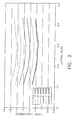
- FIG. 1 represents the thermal conductivity of thermal barrier coatings prepared from zirconia-containing ceramic compositions having various metal oxide additions, including combinations of metal oxides.
- the levels of metal oxide addition used in this evaluation are 4-6 mole %, 8 mole % and 11 mole %.
- the conductivity of the resulting coatings is evaluated after being aged at 1200°C for 2 hours in air.
- the dashed baseline shown in FIG. 1 represents the thermal conductivity of a coating prepared from a zirconia-containing ceramic composition comprising 3.95 mole % yttria addition only. As can be seen in FIG.
- FIG. 2 shows that this anti-sintering effect is defined by both the type and amount of the stabilizing component.
- Suitable second metal oxides have the formula B 2 O 3 where B is a trivalent (i.e., 3+) metal atom selected from lanthanum, gadolinium, neodymium, samarium, dysprosium, erbium, ytterbium, i.e., the second metal oxide can be selected from the group consisting of lanthana, gadolinia, neodymia, samaria, dysprosia, erbia, ytterbia, and mixtures thereof.
- the claimed invention uses lanthana as the second metal oxide.
- the particular amount of the second metal oxide will depend on a variety of factors, including the thermal insulating properties desired, the ability to minimize or reduce sintering of the resultant coating, the particular second metal oxide used, the amounts and types of first metal oxides used and like factors.
- the second metal oxide of the claimed invention is lanthana in an amount from 0.8 to 1.5 mole % of the ceramic composition.
- thermal conductivity studies have been carried out at varying levels of total stabilizer component and where lanthana is included in the stabilizer component at varying ratios of lanthana to total stabilizer component. These are represented graphically in FIG. 3 which shows the effect of total stabilizer content, as well as showing the range of lanthana to total stabilizer content ratios where thermal conductivity is minimized. Based on these thermal conductivity studies graphically represented in FIG. 3
- embodiments of these ceramic compositions having particularly desirable lower thermal conductivities are those where the total amount of the stabilizing component is from about 5 to about 9 mole % of the composition, wherein the first metal oxide is yttria in an amount from about 3 to about 6 mole %, more typically from about 4 to about 5 mole %, wherein the second metal oxide is lanthana, gadolinia or ytterbia, more typically lanthana, in an amount of from about 0.5 to about 4 mole %, more typically from about 0.8 to about 2 mole %, and wherein the mole % ratio of lanthana/gadolinia/ytterbia to yttria is in the range of from about 0.1 to about 0.5, typically from about 0.15 to about 0.35, more typically from about 0.2 to about 0.3.
- stabilizing components corresponding to the claimed invention are those where the total amount of stabilizing component is from 5.5 to 6.5 mole %, and wherein the stabilizing component consists of from 4 to 5 mole % yttria and from 0.8 to 1.5 mole % lanthana, wherein the mole % ratio of lanthana to total stabilizing component is in the range from 0.20 to 0.3.
- Thermal barrier coatings prepared from the ceramic compositions of this invention are useful with a wide variety of turbine engine (e.g., gas turbine engine) parts and components that are formed from metal substrates comprising a variety of metals and metal alloys, including superalloys, and are operated at, or exposed to, high temperatures, especially higher temperatures that occur during normal engine operation.
- turbine engine parts and components can include turbine airfoils such as blades and vanes, turbine shrouds, turbine nozzles, combustor components such as liners and deflectors, augmentor hardware of gas turbine engines and the like.
- the thermal barrier coatings of this invention can also cover a portion or all of the metal substrate.
- the thermal barrier coatings of this invention are typically used to protect, cover or overlay portions of the metal substrate of the airfoil rather than the entire component, e.g., the thermal barrier coatings cover the leading and trailing edges and other surfaces of the airfoil, but not the attachment area. While the following discussion of the thermal barrier coatings of this invention will be with reference to metal substrates of turbine engine parts and components, it should also be understood that the thermal barrier coatings of this invention are useful with metal substrates of other articles that operate at, or are exposed to, high temperatures.
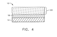
- FIG. 4 shows a partial side sectional view of an embodiment of the thermal barrier coating used with the metal substrate of an article indicated generally as 10.
- article 10 has a metal substrate indicated generally as 14.
- Substrate 14 can comprise any of a variety of metals, or more typically metal alloys, that are typically protected by thermal barrier coatings, including those based on nickel, cobalt and/or iron alloys.
- substrate 14 can comprise a high temperature, heat-resistant alloy, e.g., a superalloy.
- Such high temperature alloys are disclosed in various references, such as U.S.
- Patent 5,399,313 (Ross et al), issued March 21, 1995 and U.S. Patent 4,116,723 (Gell et al), issued September 26, 1978 .
- High temperature alloys are also generally described in Kirk-Othmer's Encyclopedia of Chemical Technology, 3rd Ed., Vol. 12, pp. 417-479 (1980 ), and Vol. 15, pp. 787-800 (1981 ).
- Illustrative high temperature nickel-based alloys are designated by the trade names Inconel®), Nimonic®, Rene® (e.g., Rene® 80-, Rene® N5 alloys), and Udimet®.
- the type of substrate 14 can vary widely, but it is representatively in the form of a turbine part or component, such as an airfoil (e.g., blade) or turbine shroud.
- article 10 can also include a bond coat layer indicated generally as 18 that is adjacent to and overlies substrate 14.
- Bond coat layer 18 is typically formed from a metallic oxidation-resistant material that protects the underlying substrate 14 and enables the thermal barrier coating indicated generally as 22 to more tenaciously adhere to substrate 14.
- Suitable materials for bond coat layer 18 include MCrAIY alloy powders, where M represents a metal such as iron, nickel, platinum or cobalt, or NiAl(Zr) compositions, as well as various Noble metal diffusion aluminides such as nickel aluminide and platinum aluminide, as well as simple aluminides (i.e., those formed without Noble metals).
- This bond coat layer 18 can be applied, deposited or otherwise formed on substrate 10 by any of a variety of conventional techniques, such as physical vapor deposition (PVD), including electron beam physical vapor deposition (EB-PVD), plasma spray, including air plasma spray (APS) and vacuum plasma spray (VPS), or other thermal spray deposition methods such as high velocity oxy-fuel (HVOF) spray, detonation, or wire spray, chemical vapor deposition (CVD), pack cementation and vapor phase aluminiding in the case of metal diffusion aluminides (see, for example, U.S. Patent 4,148,275 (Benden et al), issued April 10, 1979 ; U.S.
- PVD physical vapor deposition
- EB-PVD electron beam physical vapor deposition
- APS air plasma spray
- VPS vacuum plasma spray
- thermal spray deposition methods such as high velocity oxy-fuel (HVOF) spray, detonation, or wire spray, chemical vapor deposition (CVD), pack cementation and vapor phase
- Patent 5,928,725 (Howard et al), issued July 27, 1999 ; and U.S. Patent 6,039,810 (Mantkowski et al), issued March 21, 2000 , which disclose various apparatus and methods for applying diffusion aluminide coatings, or combinations of such techniques, such as, for example, a combination of plasma spray and diffusion aluminide techniques.
- plasma spray or diffusion techniques are employed to deposit bond coat layer 18.
- the deposited bond coat layer 18 has a thickness in the range of from about 1 to about 20 mils (from about 25 to about 500 microns).
- the thickness is more typically in the range of from about 1 about 3 mils (from about 25 to about 75 microns).
- the thickness is more typically in the range of from about 3 to about 15 mils (from about 75 to about 385 microns).
- thermal barrier coating (TBC) 22 prepared from the ceramic composition of this invention is adjacent to and overlies bond coat layer 18.
- the thickness of TBC 22 is typically in the range of from about 1 to about 100 mils (from about 25 to about 2564 microns) and will depend upon a variety of factors, including the article 10 that is involved.
- TBC 22 is typically thicker and is usually in the range of from about 30 to about 70 mils (from about 769 to about 1795 microns), more typically from about 40 to about 60 mils (from about 1333 to about 1538 microns).
- TBC 22 is typically thinner and is usually in the range of from about 1 to about 30 mils (from about 25 to about 769 microns), more typically from about 3 to about 20 mils (from about 77 to about 513 microns).
- the ceramic compositions of this invention can be applied, deposited or otherwise formed on bond coat layer 18 by any of a variety of conventional techniques, such as physical vapor deposition (PVD), including electron beam physical vapor deposition (EB-PVD), plasma spray, including air plasma spray (APS) and vacuum plasma spray (VPS), or other thermal spray deposition methods such as high velocity oxy-fuel (HVOF) spray, detonation, or wire spray; chemical vapor deposition (CVD), or combinations of plasma spray and CVD techniques.
- PVD physical vapor deposition
- EB-PVD electron beam physical vapor deposition
- plasma spray including air plasma spray (APS) and vacuum plasma spray (VPS), or other thermal spray deposition methods such as high velocity oxy-fuel (HVOF) spray, detonation, or wire spray
- HVOF high velocity oxy-fuel
- CVD chemical vapor deposition
- the particular technique used for applying, depositing or otherwise forming TBC 22 will typically depend on the composition of TBC 22, its thickness and especially the physical structure
- TBC 22 is typically formed from ceramic compositions of this invention by PVD, and especially EB-PVD techniques to provide a strain-tolerant columnar structure.
- Suitable EB-PVD techniques for use herein typically involve a coating chamber with a gas (or gas mixture) that preferably includes oxygen and an inert gas, though an oxygen-free coating atmosphere can also be employed.
- the ceramic thermal barrier coating materials are then evaporated with an electron beams focused on, for example, ingots of the ceramic thermal barrier coating materials so as to produce a vapor of metal ions, oxygen ions and one or more metal oxides.
- the metal and oxygen ions and metal oxides recombine to form TBC 22 on the surface of metal substrate 14, or more typically on bond coat layer 18.
- TBCs 22 Various types of plasma-spray techniques well known to those skilled in the art can also be utilized to form TBCs 22 from the ceramic compositions of this invention. See, for example, Kirk-Othmer Encyclopedia of Chemical Technology, 3rd Ed., Vol. 15, page 255 , and references noted therein, as well as U.S. Patent 5,332,598 (Kawasaki et al), issued July 26, 1994 ; U.S. Patent 5,047,612 (Savkar et al) issued September 10, 1991 ; and U.S. Patent. 4,741,286 (Itoh et al), issued May 3, 1998 which are instructive in regard to various aspects of plasma spraying suitable for use herein.
- typical plasma spray techniques involve the formation of a high-temperature plasma, which produces a thermal plume.
- the ceramic coating composition e.g., ceramic powders, are fed into the plume, and the high-velocity plume is directed toward the bond coat layer 18.
- plasma spray coating techniques will be well-known to those skilled in the art, including various relevant steps and process parameters such as cleaning of the bond coat surface 18 prior to deposition; grit blasting to remove oxides and roughen the surface substrate temperatures, plasma spray parameters such as spray distances (gun-to-substrate), selection of the number of spray-passes, powder feed rates, particle velocity, torch power, plasma gas selection, oxidation control to adjust oxide stoichiometry, angle-of-deposition, post-treatment of the applied coating; and the like.
- Torch power can vary in the range of about 10 kilowatts to about 200 kilowatts, and in preferred embodiments, ranges from about 40 kilowatts to about 60 kilowatts.
- the velocity of the ceramic coating composition particles flowing into the plasma plume is another parameter which is usually controlled very closely.
- Suitable plasma spray systems are described in, for example, 5,047,612 (Savkar et al) issued September 10, 1991 .
- a typical plasma spray system includes a plasma gun anode which has a nozzle pointed in the direction of the deposit-surface of the substrate being coated.
- the plasma gun is often controlled automatically, e.g., by a robotic mechanism, which is capable of moving the gun in various patterns across the substrate surface.
- the plasma plume extends in an axial direction between the exit of the plasma gun anode and the substrate surface.
- Some sort of powder injection means is disposed at a predetermined, desired axial location between the anode and the substrate surface.
- the powder injection means is spaced apart in a radial sense from the plasma plume region, and an injector tube for the powder material is situated in a position so that it can direct the powder into the plasma plume at a desired angle.
- the powder particles, entrained in a carrier gas, are propelled through the injector and into the plasma plume.
- the particles are then heated in the plasma and propelled toward the substrate.
- the particles melt, impact on the substrate, and quickly cool to form the thermal barrier coating.
Landscapes
- Chemical & Material Sciences (AREA)
- Engineering & Computer Science (AREA)
- Materials Engineering (AREA)
- Mechanical Engineering (AREA)
- Organic Chemistry (AREA)
- Chemical Kinetics & Catalysis (AREA)
- Metallurgy (AREA)
- Inorganic Chemistry (AREA)
- Ceramic Engineering (AREA)
- Physics & Mathematics (AREA)
- Plasma & Fusion (AREA)
- Manufacturing & Machinery (AREA)
- Composite Materials (AREA)
- Structural Engineering (AREA)
- General Engineering & Computer Science (AREA)
- Turbine Rotor Nozzle Sealing (AREA)
- Other Surface Treatments For Metallic Materials (AREA)
- Coating By Spraying Or Casting (AREA)
- Physical Vapour Deposition (AREA)
- Compositions Of Oxide Ceramics (AREA)
- Ceramic Products (AREA)
Description
- This invention relates to ceramic compositions for thermal barrier coatings having reduced thermal conductivity comprising zirconia and a stabilizer component having a first metal oxide of yttria and a second metal oxide of lanthana. This invention further relates to coatings prepared from such compositions, articles having such coatings and methods for preparing such coatings for the article.
- Components operating in the gas path environment of gas turbine engines are typically subjected to significant temperature extremes and degradation by oxidizing and corrosive environments. Environmental coatings and especially thermal barrier coating are an important element in current and future gas turbine engine designs, as well as other articles that are expected to operate at or be exposed to high temperatures, and thus cause the thermal barrier coating to be subjected to high surface temperatures. Examples of turbine engine parts and components for which such thermal barrier coatings are desirable include turbine blades and vanes, turbine shrouds, buckets, nozzles, combustion liners and deflectors, and the like. These thermal barrier coatings typically comprise the external portion or surface of these components are usually deposited onto a metal substrate (or more typically onto a bond coat layer on the metal substrate for better adherence) from which the part or component is formed to reduce heat flow (i.e., provide thermal insulation) and to limit (reduce) the operating temperature the underlying metal substrate of these parts and components is subjected to. This metal substrate typically comprises a metal alloy such as a nickel, cobalt, and/or iron based alloy (e.g., a high temperature superalloy).
- The thermal barrier coating is usually prepared from a ceramic material, such as a chemically (metal oxide) stabilized zirconia. Examples of such chemically stabilized zirconias include yttria-stabilized zirconia, scandia-stabilized zirconia, ceria-stabilized zirconia, calcia-stabilized zirconia, and magnesia-stabilized zirconia. The thermal barrier coating of choice is typically a yttria-stabilized zirconia ceramic coating. A representative yttria-stabilized zirconia thermal barrier coating usually comprises about 7 weight % yttria and about 93 weight % zirconia. The thickness of the thermal barrier coating depends upon the metal substrate part or component it is deposited on, but is usually in the range of from about 3 to about 70 mils (from about 75 to about 1795 microns) thick for high temperature gas turbine engine parts.
- Thermal barrier coatings comprising yttria-stabilized zirconia are usually formed on or applied to a bond coat layer of a superalloy metal substrate, such as those used in turbine airfoils, by physical vapor deposition (PVD), such as electron beam physical vapor deposition (EB-PVD) or plasma spray, such as air plasma spray (APS) techniques. Thermal barrier coatings deposited by EB-PVD techniques have a columnar, strain-tolerant microstructure that enhances the spallation performance of the deposited coating. The resistance to heat flow through this coating structure is enhanced by the defect matrix in this structure created by the "dissolving" of yttria (the dopant oxide) into zirconia, as well as process-induced porosity. This EB-PVD deposited yttria-stabilized coating provides a "feathery" microstructure that is the result of the presence of sub-grains within the columns of the coating. These sub-grain interface boundaries can be viewed as being low-angle grain boundaries formed by porosity within the columns. It is believed that the boundaries between the sub-grains make the major contribution to the reduced thermal conductivity of the EB-PVD formed thermal barrier coating structure (when compared to the bulk ceramic).
- When exposed to higher engine operating temperatures, this "feathery" microstructure begins to sinter. (This sintering process also partially takes place during the deposition of the coating by EB-PVD.) It has been found that this sintering occurs due to diffusion at the grain and sub-grain boundaries caused by the presence of defects in this microstructure. This results in coarsening and collapsing of the original porosity, as well as a reduction of the interface boundary area. These microstructural changes that occur at elevated temperatures enhance the thermal conductivity of the thermal barrier coating, and thus reduce the thermal insulation of the underlying metal substrate. Indeed, this sintering process can increase the thermal conductivity of the thermal barrier coating by as much as 20 to 30%.
- While this sintering process is particularly evident in EB-PVD deposited yttria-stabilized zirconia thermal barrier coatings, similar effects can occur in such coatings deposited by plasma spraying. In the case of plasma sprayed yttria-stabilized zirconia thermal barrier coatings, the splat boundaries are the conductivity reducing feature of such coatings. As a result, any sintering that would occur at such boundaries would be undesirable.
- Accordingly, it would be desirable to minimize or reduce this sintering process so as to maintain the insulating efficacy of the thermal barrier coating for the life of the coating, especially with regard to coatings formed by EB-PVD techniques. It would be further desirable to be able to modify the chemical composition of yttria- stabilized zirconia-based thermal barrier coating systems to reduce this sintering tendency and thus maintain or improve the reduced thermal conductivity of such coatings.
- In
US 2003/0224200 A1 , thermal barrier coating materials are disclosed. The coating materials zirconia that is partially stabilized with yttria and to which lanthana, neodymia and/or tantala are alloyed.EP 1 249 515 A2 - One aspect of this invention relates to a ceramic composition according to
claim 1 herein. - Another aspect of this invention relates to a thermally protected article according to claim 2 herein.
- Another aspect of this invention relates to a method according to claim 4 herein.
- The ceramic compositions of this invention provide several benefits when used to provide thermal barrier coatings for metal substrates of articles exposed to high temperatures, such as turbine components. Thermal barrier coatings prepared from these ceramic compositions have a reduced or minimized tendency to sinter, including coatings prepared by physical vapor deposition (PVD) techniques, such as electron beam physical vapor deposition (EB-PVD) that form columnar, strain-tolerant microstructures. Thermal barrier coatings prepared from these ceramic compositions can also possess reduced intrinsic conductivity. As a result, the thermal barrier coatings prepared from these ceramic compositions are able to maintain their reduced thermal conductivity over time and during exposure to higher temperatures, as well as temperature cycling.
- Embodiments of the invention will now be described, by way of example, with reference to the accompanying drawings, in which:
-
FIG 1 represents a bar graph showing the thermal conductivity of thermal barrier coatings prepared from zirconia-containing ceramic compositions having various metal oxide additions. -
FIG. 2 represents a bar graph showing the percentage increase in thermal conductivity of some of the thermal barrier coatings shown inFIG. 1 . -
FIG. 3 is a graphical representation of the estimated conductivity of various yttria-stabilized zirconias of thermal barrier coatings as a function of the mole % ratio of lanthana to total stabilizer component. -
FIG. 4 is a partial side sectional view of an embodiment of the thermal barrier coating and coated article of this invention. - As used herein, the term "thermal barrier coating" refers to those coatings that are capable of reducing heat flow to the underlying metal substrate of the article, i.e., forming a thermal barrier.
- As used herein, the term "comprising" means various compositions, compounds, components, layers, steps and the like can be conjointly employed in the present invention. Accordingly, the term "comprising" encompasses the more restrictive terms "consisting essentially of" and "consisting of."
- All amounts, parts, ratios and percentages used herein are by mole % unless otherwise specified.
- The ceramic compositions of this invention impart improved thermal conductivity properties to the resulting thermal barrier coatings, and in particular lower thermal conductivity. Thermal conductivity K is defined by the following equation (1):

- The thermal barrier coating compositions of this invention comprise at least 91 mole % zirconia. Typically, the compositions of this invention comprise from 91 to about 97 mole % zirconia, more typically from about 92 to about 95 mole % zirconia. The compositions of this invention further comprise a stabilizing amount of from 5.5 to 6.5 mole % of a stabilizing component consisting of a first metal oxide of yttria and a second metal oxide of lanthana. The particular amount of the stabilizing component that is "stabilizing" will depend on a variety of factors, including the thermal insulating properties desired, the ability to minimize or reduce sintering of the resultant coating, the particular amounts and types of the first and second metal oxides used and like factors.
- The first metal oxide can be selected from the group consisting of yttria, calcia, ceria, scandia, magnesia, india and mixtures thereof. The particular amount of the first metal oxide will depend on a variety of factors, including the thermal insulating properties desired, the ability to minimize or reduce sintering of the resultant coating, the particular first metal oxide used, the amounts and types of second metal oxide used and like factors. Ceramic compositions of the claimed invention use yttria as the first metal oxide in an amount of from 4 to 5% mole % of the composition.
- The ceramic compositions of this invention having improved thermal conductivity properties are based on the discovery that, to achieve any further reduction in thermal conductivity beyond that provided by the first metal oxide, a different mechanism is used. This mechanism involves including in the stabilizing component of these ceramic compositions comprising zirconia certain trivalent (i.e., 3+) dopant metal oxide(s) (i.e., the "second metal oxide(s)). Inclusion of these second metal oxides in the stabilizing component of these ceramic compositions imparts significant benefits to the resulting thermal barrier coating, including one or more of the following: (a) reducing the defect concentration at the grain boundaries or interfaces by forming stable compounds with reduced concentrations of both metal ion (i.e., cationic) and oxygen (i.e., anionic) defects; (b) enhancing segregation of higher (i.e., larger) atomic radius and/or higher (i.e., heavier) atomic mass metal oxides to the interface to reduce the diffusion processes along such boundaries or interfaces; and (c) creating additional phonon scattering defects within the zirconia lattice. Mechanisms (a) and (b) reduce the tendency of the ceramic structure to sinter, thus providing the benefit of preserving lower conductivity, while mechanism (c) provides additional reduction of the intrinsic conductivity.
- It is believed that the anti-sintering effect is related to a strong tendency of these dopant second metal oxides to segregate such that the ceramic composition comprising zirconia can be designed to either enhance segregation of the first metal oxide (e.g., yttria), or to cause co-segregation of the first metal oxide with the second metal oxide having larger (e.g., lanthanum - as per the claimed invention) or heavier atoms (e.g., ytterbium - outside the scope of the claimed invention which uses lanthana as the second metal oxide). As a result, diffusion processes along the grain boundaries or interfaces can be reduced due to a higher concentration of lower diffusing species, or by potentially forming stable components at such boundaries or interfaces (e.g., zirconate-type components).
- The presence of more than one second metal oxide can beneficially affect solubility due to lattice dimension effects. In particular, combinations of second metal oxides having different size metal atoms can decrease the solubility of the first metal oxide (e.g., yttria) in the zirconia lattice. For example, including a second metal oxide having a metal atom (e.g., lanthanum or gadolinium) of radii larger than the metal atom of the first metal oxide (e.g., yttrium) enhances segregation of first metal oxide, and at a certain first metal oxide/second metal oxide ratios, can cause formation of zirconate-type components at the intracolumnar boundaries. On the other hand, including second metal oxides having smaller radii metal atoms (e.g., ytterbium) than those of the first metal oxide will distort the zirconium-oxygen interatomic distances in the M - O - Y coordination complex, e.g., Zr - O - Y, resulting in a breakdown of the chemical bond structure and segregation of the second metal oxides of the smaller atom. Second metal oxides of such smaller but heavier atoms, such as ytterbium, can also reduce diffusion processes along the internal boundaries of the ceramic layer.
- The benefits from the inclusion of these second metal oxides on the thermal conductivity of the thermal barrier coatings prepared from these ceramic compositions is particularly shown in
FIG. 1. FIG. 1 represents the thermal conductivity of thermal barrier coatings prepared from zirconia-containing ceramic compositions having various metal oxide additions, including combinations of metal oxides. The levels of metal oxide addition used in this evaluation are 4-6 mole %, 8 mole % and 11 mole %. The conductivity of the resulting coatings is evaluated after being aged at 1200°C for 2 hours in air. The dashed baseline shown inFIG. 1 represents the thermal conductivity of a coating prepared from a zirconia-containing ceramic composition comprising 3.95 mole % yttria addition only. As can be seen inFIG. 1 , coatings prepared from ceramic compositions having 4 to 6 mole % stabilizing component addition had the lowest thermal conductivities. The percentage increase in thermal conductivity, relative to the conductivity of the same coating before aging of some of the coatings inFIG. 1 is represented as a bar graph inFIG. 2. FIG. 2 shows that this anti-sintering effect is defined by both the type and amount of the stabilizing component. - Suitable second metal oxides have the formula B2O3 where B is a trivalent (i.e., 3+) metal atom selected from lanthanum, gadolinium, neodymium, samarium, dysprosium, erbium, ytterbium, i.e., the second metal oxide can be selected from the group consisting of lanthana, gadolinia, neodymia, samaria, dysprosia, erbia, ytterbia, and mixtures thereof. The claimed invention uses lanthana as the second metal oxide. The particular amount of the second metal oxide will depend on a variety of factors, including the thermal insulating properties desired, the ability to minimize or reduce sintering of the resultant coating, the particular second metal oxide used, the amounts and types of first metal oxides used and like factors. The second metal oxide of the claimed invention is lanthana in an amount from 0.8 to 1.5 mole % of the ceramic composition.
- For yttria-stabilized zirconia thermal barrier coatings, thermal conductivity studies have been carried out at varying levels of total stabilizer component and where lanthana is included in the stabilizer component at varying ratios of lanthana to total stabilizer component. These are represented graphically in
FIG. 3 which shows the effect of total stabilizer content, as well as showing the range of lanthana to total stabilizer content ratios where thermal conductivity is minimized. Based on these thermal conductivity studies graphically represented inFIG. 3 , it has been determined that embodiments of these ceramic compositions having particularly desirable lower thermal conductivities are those where the total amount of the stabilizing component is from about 5 to about 9 mole % of the composition, wherein the first metal oxide is yttria in an amount from about 3 to about 6 mole %, more typically from about 4 to about 5 mole %, wherein the second metal oxide is lanthana, gadolinia or ytterbia, more typically lanthana, in an amount of from about 0.5 to about 4 mole %, more typically from about 0.8 to about 2 mole %, and wherein the mole % ratio of lanthana/gadolinia/ytterbia to yttria is in the range of from about 0.1 to about 0.5, typically from about 0.15 to about 0.35, more typically from about 0.2 to about 0.3. Particularly suitable embodiments of stabilizing components corresponding to the claimed invention are those where the total amount of stabilizing component is from 5.5 to 6.5 mole %, and wherein the stabilizing component consists of from 4 to 5 mole % yttria and from 0.8 to 1.5 mole % lanthana, wherein the mole % ratio of lanthana to total stabilizing component is in the range from 0.20 to 0.3. - Thermal barrier coatings prepared from the ceramic compositions of this invention are useful with a wide variety of turbine engine (e.g., gas turbine engine) parts and components that are formed from metal substrates comprising a variety of metals and metal alloys, including superalloys, and are operated at, or exposed to, high temperatures, especially higher temperatures that occur during normal engine operation. These turbine engine parts and components can include turbine airfoils such as blades and vanes, turbine shrouds, turbine nozzles, combustor components such as liners and deflectors, augmentor hardware of gas turbine engines and the like. The thermal barrier coatings of this invention can also cover a portion or all of the metal substrate. For example, with regard to airfoils such as blades, the thermal barrier coatings of this invention are typically used to protect, cover or overlay portions of the metal substrate of the airfoil rather than the entire component, e.g., the thermal barrier coatings cover the leading and trailing edges and other surfaces of the airfoil, but not the attachment area. While the following discussion of the thermal barrier coatings of this invention will be with reference to metal substrates of turbine engine parts and components, it should also be understood that the thermal barrier coatings of this invention are useful with metal substrates of other articles that operate at, or are exposed to, high temperatures.
- The various embodiments of the thermal barrier coatings of this invention are further illustrated by reference to the drawings as described hereafter. Referring to the drawings,
FIG. 4 shows a partial side sectional view of an embodiment of the thermal barrier coating used with the metal substrate of an article indicated generally as 10. As shown inFIG. 4 ,article 10 has a metal substrate indicated generally as 14.Substrate 14 can comprise any of a variety of metals, or more typically metal alloys, that are typically protected by thermal barrier coatings, including those based on nickel, cobalt and/or iron alloys. For example,substrate 14 can comprise a high temperature, heat-resistant alloy, e.g., a superalloy. Such high temperature alloys are disclosed in various references, such asU.S. Patent 5,399,313 (Ross et al), issued March 21, 1995 andU.S. Patent 4,116,723 (Gell et al), issued September 26, 1978 . High temperature alloys are also generally described in Kirk-Othmer's Encyclopedia of Chemical Technology, 3rd Ed., Vol. 12, pp. 417-479 (1980), and Vol. 15, pp. 787-800 (1981). Illustrative high temperature nickel-based alloys are designated by the trade names Inconel®), Nimonic®, Rene® (e.g., Rene® 80-, Rene® N5 alloys), and Udimet®. As described above, the type ofsubstrate 14 can vary widely, but it is representatively in the form of a turbine part or component, such as an airfoil (e.g., blade) or turbine shroud. - As shown in
FIG. 3 ,article 10 can also include a bond coat layer indicated generally as 18 that is adjacent to and overliessubstrate 14.Bond coat layer 18 is typically formed from a metallic oxidation-resistant material that protects theunderlying substrate 14 and enables the thermal barrier coating indicated generally as 22 to more tenaciously adhere tosubstrate 14. Suitable materials forbond coat layer 18 include MCrAIY alloy powders, where M represents a metal such as iron, nickel, platinum or cobalt, or NiAl(Zr) compositions, as well as various Noble metal diffusion aluminides such as nickel aluminide and platinum aluminide, as well as simple aluminides (i.e., those formed without Noble metals). Thisbond coat layer 18 can be applied, deposited or otherwise formed onsubstrate 10 by any of a variety of conventional techniques, such as physical vapor deposition (PVD), including electron beam physical vapor deposition (EB-PVD), plasma spray, including air plasma spray (APS) and vacuum plasma spray (VPS), or other thermal spray deposition methods such as high velocity oxy-fuel (HVOF) spray, detonation, or wire spray, chemical vapor deposition (CVD), pack cementation and vapor phase aluminiding in the case of metal diffusion aluminides (see, for example,U.S. Patent 4,148,275 (Benden et al), issued April 10, 1979 ;U.S. Patent 5,928,725 (Howard et al), issued July 27, 1999 ; andU.S. Patent 6,039,810 (Mantkowski et al), issued March 21, 2000 , which disclose various apparatus and methods for applying diffusion aluminide coatings, or combinations of such techniques, such as, for example, a combination of plasma spray and diffusion aluminide techniques. Typically, plasma spray or diffusion techniques are employed to depositbond coat layer 18. Usually, the depositedbond coat layer 18 has a thickness in the range of from about 1 to about 20 mils (from about 25 to about 500 microns). For bond coat layers 18 deposited by PVD techniques such as EDPVD or diffusion aluminide processes, the thickness is more typically in the range of from about 1 about 3 mils (from about 25 to about 75 microns). For bond coat layers deposited by plasma spray techniques such as APS, the thickness is more typically in the range of from about 3 to about 15 mils (from about 75 to about 385 microns). - As shown in FIG. 5, thermal barrier coating (TBC) 22 prepared from the ceramic composition of this invention is adjacent to and overlies
bond coat layer 18. The thickness ofTBC 22 is typically in the range of from about 1 to about 100 mils (from about 25 to about 2564 microns) and will depend upon a variety of factors, including thearticle 10 that is involved. For example, for turbine shrouds,TBC 22 is typically thicker and is usually in the range of from about 30 to about 70 mils (from about 769 to about 1795 microns), more typically from about 40 to about 60 mils (from about 1333 to about 1538 microns). By contrast, in the case of turbine blades,TBC 22 is typically thinner and is usually in the range of from about 1 to about 30 mils (from about 25 to about 769 microns), more typically from about 3 to about 20 mils (from about 77 to about 513 microns). - In forming
TBCs 22, the ceramic compositions of this invention can be applied, deposited or otherwise formed onbond coat layer 18 by any of a variety of conventional techniques, such as physical vapor deposition (PVD), including electron beam physical vapor deposition (EB-PVD), plasma spray, including air plasma spray (APS) and vacuum plasma spray (VPS), or other thermal spray deposition methods such as high velocity oxy-fuel (HVOF) spray, detonation, or wire spray; chemical vapor deposition (CVD), or combinations of plasma spray and CVD techniques. The particular technique used for applying, depositing or otherwise formingTBC 22 will typically depend on the composition ofTBC 22, its thickness and especially the physical structure desired forTBC 22. For example, PVD techniques tend to be useful in forming TBCs having a strain-tolerant columnar structure. By contrast, plasma spray techniques (e.g., APS) tend to create a sponge-like porous structure of open pores.TBC 22 is typically formed from ceramic compositions of this invention by PVD, and especially EB-PVD techniques to provide a strain-tolerant columnar structure. - Various types of PVD and especially EB-PVD techniques well known to those skilled in the art can also be utilized to form TBCs 22 from the ceramic compositions of this invention. See, for example,
U.S. Patent 5,645,893 (Rickerby et al), issued July 8, 1997 (especially col. 3, lines 36-63) andU.S. Patent 5,716,720 (Murphy), issued February 10, 1998 ) (especially col. 5, lines 24-61) andU.S. Patent 6,447,854 (Rigney et al), issued September 10 2002 . Suitable EB-PVD techniques for use herein typically involve a coating chamber with a gas (or gas mixture) that preferably includes oxygen and an inert gas, though an oxygen-free coating atmosphere can also be employed. The ceramic thermal barrier coating materials are then evaporated with an electron beams focused on, for example, ingots of the ceramic thermal barrier coating materials so as to produce a vapor of metal ions, oxygen ions and one or more metal oxides. The metal and oxygen ions and metal oxides recombine to formTBC 22 on the surface ofmetal substrate 14, or more typically onbond coat layer 18. - Various types of plasma-spray techniques well known to those skilled in the art can also be utilized to form TBCs 22 from the ceramic compositions of this invention. See, for example, Kirk-Othmer Encyclopedia of Chemical Technology, 3rd Ed., Vol. 15, page 255, and references noted therein, as well as
U.S. Patent 5,332,598 (Kawasaki et al), issued July 26, 1994 ;U.S. Patent 5,047,612 (Savkar et al) issued September 10, 1991 ; andU.S. Patent. 4,741,286 (Itoh et al), issued May 3, 1998 which are instructive in regard to various aspects of plasma spraying suitable for use herein. In general, typical plasma spray techniques involve the formation of a high-temperature plasma, which produces a thermal plume. The ceramic coating composition, e.g., ceramic powders, are fed into the plume, and the high-velocity plume is directed toward thebond coat layer 18. Various details of such plasma spray coating techniques will be well-known to those skilled in the art, including various relevant steps and process parameters such as cleaning of thebond coat surface 18 prior to deposition; grit blasting to remove oxides and roughen the surface substrate temperatures, plasma spray parameters such as spray distances (gun-to-substrate), selection of the number of spray-passes, powder feed rates, particle velocity, torch power, plasma gas selection, oxidation control to adjust oxide stoichiometry, angle-of-deposition, post-treatment of the applied coating; and the like. Torch power can vary in the range of about 10 kilowatts to about 200 kilowatts, and in preferred embodiments, ranges from about 40 kilowatts to about 60 kilowatts. The velocity of the ceramic coating composition particles flowing into the plasma plume (or plasma "jet") is another parameter which is usually controlled very closely. Suitable plasma spray systems are described in, for example,5,047,612 (Savkar et al) issued September 10, 1991 . - Suitable plasma spray systems are described in, for example,
5,047,612 (Savkar et al) issued September 10, 1991 . Briefly, a typical plasma spray system includes a plasma gun anode which has a nozzle pointed in the direction of the deposit-surface of the substrate being coated. The plasma gun is often controlled automatically, e.g., by a robotic mechanism, which is capable of moving the gun in various patterns across the substrate surface. The plasma plume extends in an axial direction between the exit of the plasma gun anode and the substrate surface. Some sort of powder injection means is disposed at a predetermined, desired axial location between the anode and the substrate surface. In some embodiments of such systems, the powder injection means is spaced apart in a radial sense from the plasma plume region, and an injector tube for the powder material is situated in a position so that it can direct the powder into the plasma plume at a desired angle. The powder particles, entrained in a carrier gas, are propelled through the injector and into the plasma plume. The particles are then heated in the plasma and propelled toward the substrate. The particles melt, impact on the substrate, and quickly cool to form the thermal barrier coating.
Claims (5)
- A ceramic composition, which comprises:1. at least 91 mole % zirconia; and2. from 5.5 to 6.5 mole % stabilizing component, said stabilizing component consisting of:a. yttria in an amount from 4 to 5 mole % of the composition; andb. lanthana in an amount from 0.8 to 1.5 mole % of the composition, wherein the composition has a mole % ratio of lanthana to total stabilizing component from 0.20 to 0.30.
- A thermally protected article (10), which comprises:A. a metal substrate (14);B. a bond coat layer (18) that is adjacent to and overlies the metal substrate (14); andC. a thermal barrier coating (22) comprising the composition of claim 1 that is adjacent to and overlies the bond coat layer (18).
- The article (10) of claim 2 which is a turbine engine component and wherein the thermal barrier coating (22) has a thickness of from 25 to 2500 µm (1 to 100 mils) and has a strain-tolerant columnar structure.
- A method for preparing a thermal barrier coating (22) on a bond coat layer (18) adjacent to and overlaying a metal substrate (14) the method comprising the step of:A. forming on the bond coat layer (18) a thermal barrier coating (22) by depositing a ceramic composition, which comprises:1. at least 91 mole % zirconia; and2. a stabilizing amount from 5.5 to 6.5 mole % of a stabilizer component consisting of:a. yttria in an amount from 4 to 5 mole % of the composition; andb. lanthana in an amount from 0.8 to 1.5 mole % of the composition, wherein the composition has a mole % ratio of lanthana to total stabilizing component from 0.20 to 0.30.
- The method of claim 4 wherein the ceramic composition is deposited by physical vapor deposition to form a thermal barrier coating (22) having a strain-tolerant columnar structure.
Applications Claiming Priority (2)
| Application Number | Priority Date | Filing Date | Title |
|---|---|---|---|
| US748520 | 1985-06-25 | ||
| US10/748,520 US7364802B2 (en) | 2003-12-30 | 2003-12-30 | Ceramic compositions useful in thermal barrier coatings having reduced thermal conductivity |
Publications (2)
| Publication Number | Publication Date |
|---|---|
| EP1550644A1 EP1550644A1 (en) | 2005-07-06 |
| EP1550644B1 true EP1550644B1 (en) | 2013-07-03 |
Family
ID=34574773
Family Applications (1)
| Application Number | Title | Priority Date | Filing Date |
|---|---|---|---|
| EP04256627.3A Expired - Lifetime EP1550644B1 (en) | 2003-12-30 | 2004-10-27 | Ceramic compositions useful in thermal barrier coatings having reduced thermal conductivity |
Country Status (4)
| Country | Link |
|---|---|
| US (1) | US7364802B2 (en) |
| EP (1) | EP1550644B1 (en) |
| JP (1) | JP5483792B2 (en) |
| SG (2) | SG112922A1 (en) |
Families Citing this family (31)
| Publication number | Priority date | Publication date | Assignee | Title |
|---|---|---|---|---|
| US7927722B2 (en) * | 2004-07-30 | 2011-04-19 | United Technologies Corporation | Dispersion strengthened rare earth stabilized zirconia |
| US7166373B2 (en) * | 2004-08-19 | 2007-01-23 | General Electric Company | Ceramic compositions for thermal barrier coatings with improved mechanical properties |
| US7429424B2 (en) * | 2004-12-06 | 2008-09-30 | General Electric Company | Sintering resistant, low conductivity, high stability thermal barrier coating/environmental barrier coating system for a ceramic-matrix composite (CMC) article to improve high temperature capability |
| US7476453B2 (en) * | 2004-12-06 | 2009-01-13 | General Electric Company | Low thermal conductivity thermal barrier coating system and method therefor |
| US7364807B2 (en) * | 2004-12-06 | 2008-04-29 | General Electric Company | Thermal barrier coating/environmental barrier coating system for a ceramic-matrix composite (CMC) article to improve high temperature capability |
| US20070292624A1 (en) * | 2005-06-28 | 2007-12-20 | General Electric Company | Low conductivity, thermal barrier coating system for ceramic matrix composite (CMC) articles |
| US7740960B1 (en) * | 2005-08-26 | 2010-06-22 | The United States Of America As Represented By The Secretary Of The Army | Multifunctionally graded environmental barrier coatings for silicon-base ceramic components |
| US7700508B1 (en) * | 2005-08-26 | 2010-04-20 | The United States Of Americas As Represented By The Secretary Of The Army | Low conductivity and high toughness tetragonal phase structured ceramic thermal barrier coatings |
| JP5063685B2 (en) * | 2006-05-26 | 2012-10-31 | プラクスエア・テクノロジー・インコーポレイテッド | Blade tip coating using high-purity powder |
| CA2585992C (en) * | 2006-06-08 | 2014-06-17 | Sulzer Metco (Us) Inc. | Dysprosia stabilized zirconia abradable |
| US9447503B2 (en) | 2007-05-30 | 2016-09-20 | United Technologies Corporation | Closed pore ceramic composite article |
| US20090186237A1 (en) | 2008-01-18 | 2009-07-23 | Rolls-Royce Corp. | CMAS-Resistant Thermal Barrier Coatings |
| WO2009119495A1 (en) * | 2008-03-24 | 2009-10-01 | 京セラ株式会社 | Ceramic for decorative part |
| EP2133572B1 (en) | 2008-06-12 | 2017-11-15 | General Electric Company | Centrifugal compressor for wet gas environments and method of manufacture |
| WO2009157174A1 (en) * | 2008-06-23 | 2009-12-30 | 株式会社 東芝 | Steam turbine and steam turbine blade |
| WO2010123761A2 (en) * | 2009-04-20 | 2010-10-28 | Borgwarner Inc. | Insulating spacer for ball bearing cartridge |
| JP5723387B2 (en) | 2009-12-29 | 2015-05-27 | スリーエム イノベイティブ プロパティズ カンパニー | Zirconia-based materials doped with yttrium and lanthanum |
| JP5814937B2 (en) | 2009-12-29 | 2015-11-17 | スリーエム イノベイティブ プロパティズ カンパニー | Zirconia-based particles doped with lanthanide elements |
| CA2806172C (en) * | 2010-07-23 | 2015-04-28 | Rolls-Royce Corporation | Thermal barrier coatings including cmas-resistant thermal barrier coating layers |
| JP5892873B2 (en) * | 2012-06-19 | 2016-03-23 | 株式会社東芝 | Steam turbine |
| US9816392B2 (en) * | 2013-04-10 | 2017-11-14 | General Electric Company | Architectures for high temperature TBCs with ultra low thermal conductivity and abradability and method of making |
| US11479846B2 (en) | 2014-01-07 | 2022-10-25 | Honeywell International Inc. | Thermal barrier coatings for turbine engine components |
| DE102017005800A1 (en) * | 2017-06-21 | 2018-12-27 | H.C. Starck Surface Technology and Ceramic Powders GmbH | Zirconia powder for thermal spraying |
| US20190017177A1 (en) | 2017-07-17 | 2019-01-17 | Rolls-Royce Corporation | Thermal barrier coatings for components in high-temperature mechanical systems |
| US11655543B2 (en) | 2017-08-08 | 2023-05-23 | Rolls-Royce Corporation | CMAS-resistant barrier coatings |
| DE102018203895A1 (en) * | 2018-03-14 | 2019-09-19 | Siemens Aktiengesellschaft | Ceramic material, layer and layer system |
| DE102018204498A1 (en) * | 2018-03-23 | 2019-09-26 | Siemens Aktiengesellschaft | Ceramic material based on zirconium oxide with other oxides |
| DE102018215223A1 (en) * | 2018-09-07 | 2020-03-12 | Siemens Aktiengesellschaft | Ceramic material based on zirconium oxide with additional oxides and layer system |
| DE102018221940A1 (en) * | 2018-12-17 | 2020-06-18 | Siemens Aktiengesellschaft | Ceramic material, layer and layer system |
| DE102019217445A1 (en) * | 2019-11-12 | 2021-05-12 | Siemens Aktiengesellschaft | Ceramic material, powder and layer system |
| CN120463493B (en) * | 2025-07-09 | 2025-11-14 | 浙江金琨西立锆珠有限公司 | A composite rare earth oxide co-stabilized zirconia ceramic microsphere and its preparation method |
Citations (1)
| Publication number | Priority date | Publication date | Assignee | Title |
|---|---|---|---|---|
| US20030224200A1 (en) * | 2002-05-30 | 2003-12-04 | General Electric Company | Thermal barrier coating material |
Family Cites Families (35)
| Publication number | Priority date | Publication date | Assignee | Title |
|---|---|---|---|---|
| US3525597A (en) * | 1968-11-13 | 1970-08-25 | Us Air Force | Transparent zirconia and process for making same |
| JPS5833190B2 (en) * | 1977-10-15 | 1983-07-18 | トヨタ自動車株式会社 | Stabilized zirconia for oxygen ion conductive solid electrolyte |
| US4360598A (en) * | 1980-03-26 | 1982-11-23 | Ngk Insulators, Ltd. | Zirconia ceramics and a method of producing the same |
| US4485151A (en) * | 1982-05-06 | 1984-11-27 | The United States Of America As Represented By The Administrator Of The National Aeronautics And Space Administration | Thermal barrier coating system |
| US4535033A (en) * | 1983-08-16 | 1985-08-13 | The United States Of America As Represented By The Administrator Of The National Aeronautics And Space Administration | Thermal barrier coating system |
| US4764491A (en) * | 1987-05-11 | 1988-08-16 | General Motors Corporation | Low temperature sintering of yttria stabilized zirconia with lanthana borate additions |
| US5180696A (en) * | 1987-06-11 | 1993-01-19 | Hitachi Metals, Ltd. | High-toughness zro2 sintered body and method of producing same |
| DE3744145A1 (en) * | 1987-12-24 | 1989-07-06 | Asea Brown Boveri | SUPER LADDER AND METHOD FOR THE PRODUCTION THEREOF |
| GB9617267D0 (en) | 1996-08-16 | 1996-09-25 | Rolls Royce Plc | A metallic article having a thermal barrier coating and a method of application thereof |
| US6930066B2 (en) * | 2001-12-06 | 2005-08-16 | Siemens Westinghouse Power Corporation | Highly defective oxides as sinter resistant thermal barrier coating |
| US6924040B2 (en) * | 1996-12-12 | 2005-08-02 | United Technologies Corporation | Thermal barrier coating systems and materials |
| US6177200B1 (en) * | 1996-12-12 | 2001-01-23 | United Technologies Corporation | Thermal barrier coating systems and materials |
| US6117560A (en) * | 1996-12-12 | 2000-09-12 | United Technologies Corporation | Thermal barrier coating systems and materials |
| US6261643B1 (en) * | 1997-04-08 | 2001-07-17 | General Electric Company | Protected thermal barrier coating composite with multiple coatings |
| US6015630A (en) * | 1997-04-10 | 2000-01-18 | The University Of Connecticut | Ceramic materials for thermal barrier coatings |
| US5876860A (en) * | 1997-12-09 | 1999-03-02 | N.V. Interturbine | Thermal barrier coating ceramic structure |
| EP0969117A3 (en) * | 1998-07-01 | 2001-01-10 | General Electric Company | Method of forming a thermal barrier coating system |
| FR2784120B1 (en) * | 1998-10-02 | 2000-11-03 | Snecma | LOW THERMAL CONDUCTIVITY THERMAL BARRIER COATING, METAL PIECE PROTECTED BY THIS COATING, METHOD FOR DEPOSITING THE COATING |
| FR2798654B1 (en) * | 1999-09-16 | 2001-10-19 | Snecma | LOW THERMAL CONDUCTIVITY THERMAL BARRIER COMPOSITION, SUPERALLOY MECHANICAL PART PROTECTED BY A CERAMIC COATING HAVING SUCH A COMPOSITION, AND METHOD FOR PRODUCING THE CERAMIC COATING |
| US6812176B1 (en) * | 2001-01-22 | 2004-11-02 | Ohio Aerospace Institute | Low conductivity and sintering-resistant thermal barrier coatings |
| US6461107B1 (en) * | 2001-03-27 | 2002-10-08 | General Electric Company | Turbine blade tip having thermal barrier coating-formed micro cooling channels |
| US6461108B1 (en) * | 2001-03-27 | 2002-10-08 | General Electric Company | Cooled thermal barrier coating on a turbine blade tip |
| US6586115B2 (en) | 2001-04-12 | 2003-07-01 | General Electric Company | Yttria-stabilized zirconia with reduced thermal conductivity |
| US6887588B2 (en) * | 2001-09-21 | 2005-05-03 | General Electric Company | Article protected by thermal barrier coating having a sintering inhibitor, and its fabrication |
| US6821641B2 (en) | 2001-10-22 | 2004-11-23 | General Electric Company | Article protected by thermal barrier coating having a sintering inhibitor, and its fabrication |
| UA74150C2 (en) * | 2002-01-09 | 2005-11-15 | Дженерал Електрік Компані | method fOR formING thermal barrier coating (VARIANTS) and thermal barrier coating |
| US6730422B2 (en) * | 2002-08-21 | 2004-05-04 | United Technologies Corporation | Thermal barrier coatings with low thermal conductivity |
| US6982126B2 (en) * | 2003-11-26 | 2006-01-03 | General Electric Company | Thermal barrier coating |
| US6875529B1 (en) * | 2003-12-30 | 2005-04-05 | General Electric Company | Thermal barrier coatings with protective outer layer for improved impact and erosion resistance |
| US6916561B1 (en) * | 2003-12-30 | 2005-07-12 | General Electric Company | Thermal barrier coatings with lower porosity for improved impact and erosion resistance |
| US6858334B1 (en) * | 2003-12-30 | 2005-02-22 | General Electric Company | Ceramic compositions for low conductivity thermal barrier coatings |
| US6887595B1 (en) * | 2003-12-30 | 2005-05-03 | General Electric Company | Thermal barrier coatings having lower layer for improved adherence to bond coat |
| US20050142393A1 (en) * | 2003-12-30 | 2005-06-30 | Boutwell Brett A. | Ceramic compositions for thermal barrier coatings stabilized in the cubic crystalline phase |
| US7255940B2 (en) * | 2004-07-26 | 2007-08-14 | General Electric Company | Thermal barrier coatings with high fracture toughness underlayer for improved impact resistance |
| US7166373B2 (en) * | 2004-08-19 | 2007-01-23 | General Electric Company | Ceramic compositions for thermal barrier coatings with improved mechanical properties |
-
2003
- 2003-12-30 US US10/748,520 patent/US7364802B2/en not_active Expired - Fee Related
-
2004
- 2004-10-26 SG SG200406244A patent/SG112922A1/en unknown
- 2004-10-26 SG SG200704905-9A patent/SG133617A1/en unknown
- 2004-10-27 EP EP04256627.3A patent/EP1550644B1/en not_active Expired - Lifetime
- 2004-10-29 JP JP2004315273A patent/JP5483792B2/en not_active Expired - Fee Related
Patent Citations (1)
| Publication number | Priority date | Publication date | Assignee | Title |
|---|---|---|---|---|
| US20030224200A1 (en) * | 2002-05-30 | 2003-12-04 | General Electric Company | Thermal barrier coating material |
Also Published As
| Publication number | Publication date |
|---|---|
| US7364802B2 (en) | 2008-04-29 |
| SG133617A1 (en) | 2007-07-30 |
| US20050142395A1 (en) | 2005-06-30 |
| JP2005200291A (en) | 2005-07-28 |
| EP1550644A1 (en) | 2005-07-06 |
| SG112922A1 (en) | 2005-07-28 |
| JP5483792B2 (en) | 2014-05-07 |
Similar Documents
| Publication | Publication Date | Title |
|---|---|---|
| EP1550644B1 (en) | Ceramic compositions useful in thermal barrier coatings having reduced thermal conductivity | |
| US6960395B2 (en) | Ceramic compositions useful for thermal barrier coatings having reduced thermal conductivity | |
| EP1550645B1 (en) | Ceramic compositions for thermal barrier coatings stabilized in the cubic crystalline phase | |
| US6887595B1 (en) | Thermal barrier coatings having lower layer for improved adherence to bond coat | |
| EP1536040B1 (en) | Strengthened bond coats for thermal barrier coatings | |
| US6875529B1 (en) | Thermal barrier coatings with protective outer layer for improved impact and erosion resistance | |
| US6858334B1 (en) | Ceramic compositions for low conductivity thermal barrier coatings | |
| US7255940B2 (en) | Thermal barrier coatings with high fracture toughness underlayer for improved impact resistance | |
| EP1375701B1 (en) | Thermal barrier coating material | |
| US6869703B1 (en) | Thermal barrier coatings with improved impact and erosion resistance | |
| EP1588992A1 (en) | Mixed metal oxide ceramic compositions for reduced conductivity thermal barrier coatings | |
| US6686060B2 (en) | Thermal barrier coating material | |
| US7166373B2 (en) | Ceramic compositions for thermal barrier coatings with improved mechanical properties | |
| US6916561B1 (en) | Thermal barrier coatings with lower porosity for improved impact and erosion resistance | |
| US7476453B2 (en) | Low thermal conductivity thermal barrier coating system and method therefor |
Legal Events
| Date | Code | Title | Description |
|---|---|---|---|
| PUAI | Public reference made under article 153(3) epc to a published international application that has entered the european phase |
Free format text: ORIGINAL CODE: 0009012 |
|
| AK | Designated contracting states |
Kind code of ref document: A1 Designated state(s): AT BE BG CH CY CZ DE DK EE ES FI FR GB GR HU IE IT LI LU MC NL PL PT RO SE SI SK TR |
|
| AX | Request for extension of the european patent |
Extension state: AL HR LT LV MK |
|
| 17P | Request for examination filed |
Effective date: 20060109 |
|
| AKX | Designation fees paid |
Designated state(s): DE FR GB |
|
| 17Q | First examination report despatched |
Effective date: 20060221 |
|
| GRAP | Despatch of communication of intention to grant a patent |
Free format text: ORIGINAL CODE: EPIDOSNIGR1 |
|
| GRAS | Grant fee paid |
Free format text: ORIGINAL CODE: EPIDOSNIGR3 |
|
| GRAA | (expected) grant |
Free format text: ORIGINAL CODE: 0009210 |
|
| AK | Designated contracting states |
Kind code of ref document: B1 Designated state(s): DE FR GB |
|
| REG | Reference to a national code |
Ref country code: GB Ref legal event code: FG4D |
|
| REG | Reference to a national code |
Ref country code: DE Ref legal event code: R096 Ref document number: 602004042589 Country of ref document: DE Effective date: 20130829 |
|
| PLBE | No opposition filed within time limit |
Free format text: ORIGINAL CODE: 0009261 |
|
| STAA | Information on the status of an ep patent application or granted ep patent |
Free format text: STATUS: NO OPPOSITION FILED WITHIN TIME LIMIT |
|
| 26N | No opposition filed |
Effective date: 20140404 |
|
| REG | Reference to a national code |
Ref country code: DE Ref legal event code: R097 Ref document number: 602004042589 Country of ref document: DE Effective date: 20140404 |
|
| REG | Reference to a national code |
Ref country code: FR Ref legal event code: PLFP Year of fee payment: 12 |
|
| PGFP | Annual fee paid to national office [announced via postgrant information from national office to epo] |
Ref country code: DE Payment date: 20151028 Year of fee payment: 12 Ref country code: GB Payment date: 20151027 Year of fee payment: 12 |
|
| PGFP | Annual fee paid to national office [announced via postgrant information from national office to epo] |
Ref country code: FR Payment date: 20151019 Year of fee payment: 12 |
|
| REG | Reference to a national code |
Ref country code: DE Ref legal event code: R119 Ref document number: 602004042589 Country of ref document: DE |
|
| GBPC | Gb: european patent ceased through non-payment of renewal fee |
Effective date: 20161027 |
|
| REG | Reference to a national code |
Ref country code: FR Ref legal event code: ST Effective date: 20170630 |
|
| PG25 | Lapsed in a contracting state [announced via postgrant information from national office to epo] |
Ref country code: FR Free format text: LAPSE BECAUSE OF NON-PAYMENT OF DUE FEES Effective date: 20161102 Ref country code: DE Free format text: LAPSE BECAUSE OF NON-PAYMENT OF DUE FEES Effective date: 20170503 Ref country code: GB Free format text: LAPSE BECAUSE OF NON-PAYMENT OF DUE FEES Effective date: 20161027 |