EP1550622A1 - Schwingförderboden - Google Patents
Schwingförderboden Download PDFInfo
- Publication number
- EP1550622A1 EP1550622A1 EP04029671A EP04029671A EP1550622A1 EP 1550622 A1 EP1550622 A1 EP 1550622A1 EP 04029671 A EP04029671 A EP 04029671A EP 04029671 A EP04029671 A EP 04029671A EP 1550622 A1 EP1550622 A1 EP 1550622A1
- Authority
- EP
- European Patent Office
- Prior art keywords
- deck
- conveyor
- force
- rib
- support
- Prior art date
- Legal status (The legal status is an assumption and is not a legal conclusion. Google has not performed a legal analysis and makes no representation as to the accuracy of the status listed.)
- Granted
Links
Images


Classifications
-
- B—PERFORMING OPERATIONS; TRANSPORTING
- B65—CONVEYING; PACKING; STORING; HANDLING THIN OR FILAMENTARY MATERIAL
- B65G—TRANSPORT OR STORAGE DEVICES, e.g. CONVEYORS FOR LOADING OR TIPPING, SHOP CONVEYOR SYSTEMS OR PNEUMATIC TUBE CONVEYORS
- B65G27/00—Jigging conveyors
- B65G27/04—Load carriers other than helical or spiral channels or conduits
-
- B—PERFORMING OPERATIONS; TRANSPORTING
- B65—CONVEYING; PACKING; STORING; HANDLING THIN OR FILAMENTARY MATERIAL
- B65G—TRANSPORT OR STORAGE DEVICES, e.g. CONVEYORS FOR LOADING OR TIPPING, SHOP CONVEYOR SYSTEMS OR PNEUMATIC TUBE CONVEYORS
- B65G27/00—Jigging conveyors
- B65G27/02—Jigging conveyors comprising helical or spiral channels or conduits for elevation of materials
-
- B—PERFORMING OPERATIONS; TRANSPORTING
- B65—CONVEYING; PACKING; STORING; HANDLING THIN OR FILAMENTARY MATERIAL
- B65G—TRANSPORT OR STORAGE DEVICES, e.g. CONVEYORS FOR LOADING OR TIPPING, SHOP CONVEYOR SYSTEMS OR PNEUMATIC TUBE CONVEYORS
- B65G2207/00—Indexing codes relating to constructional details, configuration and additional features of a handling device, e.g. Conveyors
- B65G2207/24—Helical or spiral conveying path
Definitions
- This disclosure generally relates to vibratory process equipment and, more particularly, to decks used in vibratory conveyors.
- Vibratory conveyors are generally known in the art for transporting objects using a vibratory force.
- Such conveyors typically include a deck or other structure that has a conveying surface which defines a path along which objects are conveyed.
- the path defined by the deck may be straight, curved, inclined, declined, spiral, or other configuration.
- the deck is typically constructed of plate steel. As a result, when viewed in cross-section, the conveying surface defined by the deck is typically “flat” across the width of the deck. Stated alternatively, the conveying surface is substantially linear across its width.
- While a flat deck is satisfactory for many applications, it may cause unintended and undesirable results when used to convey certain objects.
- the objects may roll transversely across the width of the deck, and therefore are not located on the deck with any degree of certainty.
- the cylindrical objects may become oriented transversely across the deck, and therefore more easily roll into and possibly damage other objects on the deck.
- a conveyor deck having a conveying surface and a back surface.
- a rib is attached to the back surface and a "force assembly" is coupled to the rib.
- the deck may be bowed either concavely or convexly. If formed with a concave bend, the conveying surface of the deck, when viewed in cross-section, will have a localized low point adjacent the rib that defines a deck along which objects are conveyed.
- the concave shape also tends to orient cylindrical objects longitudinally on the deck, defined herein as parallel to the direction of travel.
- the bowed cross-sectional shape allows the deck to be formed more nearly to a pure helicoid, where the pitch of the deck is consistent along the entire conveyor path and each radial cross section of the deck will have linear opposing deck edges, regardless of whether the deck is curved concavely or convexly. While the disclosed embodiment is a spiral conveyor, it will be appreciated that the bowed deck shape provides advantages for other conveyor path configurations, including linear, curved, and inclined paths.
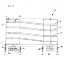
- a spiral conveyor 10 having a frame 12 supporting a spiral deck 16.
- the frame 12 is resiliently supported above the ground or mounting surface by isolation means, such as springs 18.
- An exciter mass 20 and vibration generators 22 are resiliently coupled to the frame 12, such as by springs 21 (FIG. 2).
- Any generally known vibration generators may be used, such as motors having rotating shafts carrying eccentric weights.
- the spiral deck 16 is oriented to vertically elevate work pieces, such as hot castings, from an inlet 24 to an outlet 26.
- the deck 16 defines a conveying surface 16a for receiving the work pieces and a back surface 16b (FIGS. 4 & 5).
- the work pieces may be transferred from an origination point, such as a molding line, to the inlet 24 by any conveying means, such as by a linear vibratory or other type of conveyor (not shown).
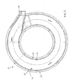
- the spiral deck 16 is formed in a helical pattern so that, as the work pieces move circumferentially around the deck, they are also elevated in the vertical direction.
- the spiral deck 16 defines a plurality of stacked tier segments 14.
- the work piece may be deposited onto an outlet transport (not shown), which may also be a conveyor. While the conveyor 10 is described herein as conveying the work pieces vertically upward, the inlet and outlet may be reversed so that the work pieces are conveyed vertically downward along the spiral deck 16.
- the vibration generators 22 may be controlled in any known fashion to produce the desired vibrational motion of the frame 12 and coupled spiral deck 16, thereby to advance the work pieces along the deck 16.
- the motors may be rotated in opposite directions (i.e., counter-rotated) and controlled to maintain a desired phase angle between the eccentric weights. While the illustrated embodiment is a two mass system, it will be appreciated that the conveyor 10 may be provided as a single mass or brute force system.
- the spiral deck 16 includes an inner edge 19 and an outer edge 21.
- An inner housing wall 30 is coupled to the spiral deck inner edge 19 and an outer housing wall 32 is coupled to the spiral deck outer edge 21.
- the deck inner edge 19 is secured to the inner housing wall 30 by a first or inner wall support assembly 34, which may clamp the deck inner edge 19 between a bottom flange 36 and a top retainer 38 (FIG. 5).
- the deck outer edge 21 may be secured to the outer housing wall 32 by a second or outer wall support assembly 40, which may clamp the deck outer edge 21 between a bottom flange 42 and a top retainer 44.
- a plurality of access doors 46 (FIG. 1) may be formed in the housing outer wall 32 for accessing the different tier portions 14 of the deck 16, should the outer housing wall 32 completely enclose the deck 16.
- a rib assembly 50 is attached to the deck back surface 16b between the inner and outer deck edges 19, 21 (FIGS. 4-6).
- the rib assembly may 50 may extend continuously along the deck 16 in the longitudinal direction, so that, in the illustrated embodiment, the rib assembly has a spiral shape.
- the rib assembly 50 may include a pair of ribs 52 having aligned transverse apertures.
- a force assembly 60 coupled to the rib assembly 50 to create a force that bends the deck 16 into an arcuate shape when viewed in cross-section.
- the exemplary force assembly 60 includes a pin 62 mechanically coupled to the rib assembly 50, such as by insertion through the transverse apertures formed in the ribs 52.
- a cross support 64 is spaced from the deck 16 and supported by the inner and outer housing walls 30, 32. As shown, the cross support 64 is provided as a tubular steel member, and has apertures 65 formed in the upper and lower support surfaces 64a, 64b.
- a link 66 is inserted through the apertures in the cross support 64 and defines a first end 68 coupled to the pin 62 and a second end 70. The link 66 also includes a threaded portion 72 for receiving a nut 74.
- the nut 74 may be adjusted on the link threaded portion 72 to generate a force in the link 66 that is transferred by the rib assembly 50 to the deck 16, thereby to bend the deck 16 in an arcuate shape. As shown in FIGS. 4 & 5, the nut 74 may be located below the cross support 64. In FIG. 4, the deck 16 is shown in a relaxed state, where the force assembly 60 applies no force to the deck 16. The nut 74 may be adjusted upwardly along the threaded portion 72 so that the nut engages the lower surface of the cross support 64, thereby to create tension in the link 66. The tension in the link 66 is transferred by the pin 62 as a downwardly directed force acting against the rib assembly 50 and attached deck 16. The nut 74 may be adjusted along the threaded portion 72 to create a tension force in the link 66 sufficient to bend the deck 16 into an arcuate shape, as shown in FIG. 5.
- the pin 62 may be provided as a bar coupled to the ribs 52 and formed with a threaded aperture.
- the link 66 may be a bolt or threaded rod with the first end 68 threadably engaging the bar threaded aperture.
- the second end 70 of the bolt is a bolt head, which takes the place of the nut 74. Accordingly, bolt may be threaded into the bar threaded aperture to create the tension force.
- the ribs 52 may project sufficiently past the pin 62 to define stop ends 76 that are engageable with the top surface 64a of the cross support, thereby to limit the amount of deflection of the deck 16.
- the rib stop ends 76 are spaced from the top surface of the cross support by a known distance "D".
- the stop ends 76 are drawn toward and eventually engage the cross support top surface 64a, thereby limiting the amount of deflection of the deck 16.
- the conveying surface 16a may also be formed with a convex arcuate shape.
- the force assembly 60 may be modified so that the link threaded portion 72 is adjacent an upper surface of the cross support 64, and the nut 74 may be adjusted downwardly along the threaded portion to engage the upper surface 64a of the cross support. Consequently, a compression force is generated in the link 66 that is transferred by the pin 62 as an upwardly directed force against the rib assembly 60 and attached deck 16.
- a nut may simply be provided on the bolt above the cross support upper surface 64a, and the nut may be adjusted downwardly along the bolt to engage the upper surface 64a.
- FIGS. 4 & 5 While only a single force assembly 60 is shown coupled to the rib assembly 60 in FIGS. 4 & 5, it will be appreciated that a plurality of force assemblies may be coupled to the rib assembly 60 at points spaced along the longitudinal length of the rib assembly 50. In the segment of the deck 16 shown in FIG. 6, a total of three force assemblies 60 are shown coupled to the rib assembly 50. FIG. 6 also illustrates the ribs 62 extending along the longitudinal length of the deck 16. Furthermore, while a single deck segment is shown in FIG. 6, it will be appreciated that multiple deck segments may be fabricated independently and assembled to create the complete conveyor deck. The improved fit of the arcuate shaped deck allows the ends of the deck segments to be more reliably located, thereby facilitating assembly of mating deck segments.
Landscapes
- Engineering & Computer Science (AREA)
- Mechanical Engineering (AREA)
- Jigging Conveyors (AREA)
- Fertilizing (AREA)
Applications Claiming Priority (2)
| Application Number | Priority Date | Filing Date | Title |
|---|---|---|---|
| US53232703P | 2003-12-23 | 2003-12-23 | |
| US532327P | 2003-12-23 |
Publications (2)
| Publication Number | Publication Date |
|---|---|
| EP1550622A1 true EP1550622A1 (de) | 2005-07-06 |
| EP1550622B1 EP1550622B1 (de) | 2007-07-18 |
Family
ID=34573057
Family Applications (1)
| Application Number | Title | Priority Date | Filing Date |
|---|---|---|---|
| EP04029671A Expired - Lifetime EP1550622B1 (de) | 2003-12-23 | 2004-12-15 | Schwingförderboden |
Country Status (8)
| Country | Link |
|---|---|
| US (1) | US7487868B2 (de) |
| EP (1) | EP1550622B1 (de) |
| JP (1) | JP2005179065A (de) |
| AT (1) | ATE367337T1 (de) |
| AU (1) | AU2004240148A1 (de) |
| BR (1) | BRPI0405794A (de) |
| CA (1) | CA2490324A1 (de) |
| DE (1) | DE602004007609T2 (de) |
Families Citing this family (4)
| Publication number | Priority date | Publication date | Assignee | Title |
|---|---|---|---|---|
| US7296951B2 (en) * | 2004-08-25 | 2007-11-20 | General Kinematics Corporation | Vibratory spiral conveyor |
| US9950870B2 (en) | 2012-01-20 | 2018-04-24 | Mayfran International | Vertical spiral conveyor |
| US9321117B2 (en) | 2014-03-18 | 2016-04-26 | Vermeer Manufacturing Company | Automatic system for abrasive hardfacing |
| CN109353760B (zh) * | 2018-12-13 | 2020-09-11 | 温州市聚达信息科技有限公司 | 美容化妆品的智能制造系统 |
Citations (5)
| Publication number | Priority date | Publication date | Assignee | Title |
|---|---|---|---|---|
| US3087602A (en) * | 1960-05-25 | 1963-04-30 | Hooker Chemical Corp | Conveyor apparatus |
| US4482046A (en) * | 1982-04-15 | 1984-11-13 | General Kinematics Corporation | Flexible trough vibratory conveyor |
| US4787502A (en) * | 1986-08-04 | 1988-11-29 | Triple/S Dynamics Inc. | Apparatus and method for conveying material |
| US5375694A (en) * | 1993-08-16 | 1994-12-27 | Hyer Industries, Inc. | Vibratory feeder |
| US5931286A (en) * | 1995-02-28 | 1999-08-03 | Kramer Ag Basserdorf | Driving unit for vibration conveyors |
Family Cites Families (40)
| Publication number | Priority date | Publication date | Assignee | Title |
|---|---|---|---|---|
| US2688394A (en) * | 1951-06-18 | 1954-09-07 | Hurd And James Inc | Belt conveyer for loose aggregates |
| US2927683A (en) | 1957-12-26 | 1960-03-08 | Carrier Conveyor Corp | Drive for a helical vibratory conveyor |
| DE1800588A1 (de) * | 1968-10-02 | 1970-06-11 | Bosch Gmbh Robert | Durch mindestens einen Unwuchterreger angetriebener Schwinger |
| US3664487A (en) | 1969-05-23 | 1972-05-23 | Carl H Ballenger | Endless helical conveyer and belt |
| US3850288A (en) | 1969-07-22 | 1974-11-26 | Gen Kinematics Corp | Vertical lift conveyor |
| DE2037371C3 (de) | 1969-07-22 | 1975-05-28 | General Kinematics Corp., Barrington, Ill. (V.St.A.) | Vertikalschwingförderer zum Befördern eines stückigen oder körnigen Materials |
| US3712459A (en) | 1971-02-12 | 1973-01-23 | Gen Kinematics Corp | Vibratory conveyor |
| US3776352A (en) | 1971-07-08 | 1973-12-04 | Gen Kinematics Corp | Sealed drive for vibratory material handling device |
| US3789977A (en) * | 1972-01-14 | 1974-02-05 | Gen Kinematics Corp | Vibratory vertical lift conveyor |
| US4140215A (en) | 1974-08-05 | 1979-02-20 | General Kinematics Corporation | Method of achieving vertical lift of particulate material |
| US4181216A (en) | 1977-11-25 | 1980-01-01 | George Cipu | Reversible vibrator, bowl feeder with angled spring supports |
| US4267919A (en) | 1979-05-21 | 1981-05-19 | Rexnord Inc. | Vibrating spiral conveyor drive |
| US4611709A (en) | 1979-07-02 | 1986-09-16 | General Kinematics | Vibratory conveyor |
| US4709507A (en) | 1985-09-19 | 1987-12-01 | General Kinematics Corporation | Tumbling apparatus |
| US4787504A (en) * | 1986-10-06 | 1988-11-29 | Ppg Industries, Inc. | Adjustable radius conveyor roll |
| US4775284A (en) | 1986-12-02 | 1988-10-04 | General Kinematics Corporation | Vertical mass flow conveyor |
| EP0287860A3 (de) * | 1987-03-31 | 1989-06-07 | Asmo Co., Ltd. | Mechanismus zum Umwandeln von Drehbewegung in eine hin- und hergehende Bewegung |
| US5024320A (en) | 1987-05-08 | 1991-06-18 | General Kinematics Corporation | Vibratory spiral elevator |
| US4844236A (en) | 1987-07-13 | 1989-07-04 | General Kinematics Corporation | Inclined vibratory conveyor |
| US4875343A (en) | 1988-03-14 | 1989-10-24 | Jeppsson E Hakan O | Climate chamber with conveyor |
| US5054606A (en) | 1988-05-11 | 1991-10-08 | General Kinematics Corporation | Control system for vibratory apparatus |
| KR910000494A (ko) * | 1988-06-05 | 1991-01-29 | 히데하루 나가하마 | 벨트콘베이어 승계 (乘繼) 장치 |
| US4926601A (en) | 1989-03-09 | 1990-05-22 | General Kinematics Corporation | Vibratory tumbling apparatus |
| US4953365A (en) | 1989-06-28 | 1990-09-04 | Liquid Carbonic Corporation | Helical conveyor freezer |
| GB2235756A (en) | 1989-09-05 | 1991-03-13 | Star Refrigeration | Helical refrigeration apparatus |
| DE4106712C1 (en) | 1991-03-02 | 1992-06-25 | Joest Gmbh + Co Kg, 4408 Duelmen, De | Spiral conveyor with vibration drive - has tubular guide above conveyed material, whose gas outlets forming slit, pointing downwards to material |
| US5178259A (en) | 1991-04-30 | 1993-01-12 | General Kinematics | Vibratory conveying apparatus |
| US5413213A (en) | 1992-07-25 | 1995-05-09 | Korber Ag | Apparatus for transporting mass flows of articles |
| DE4228543C1 (de) | 1992-08-27 | 1993-11-25 | Joest Gmbh & Co Kg | Mittels eines Schwingantriebes angetriebener Wendelförderer |
| US5713457A (en) | 1995-12-06 | 1998-02-03 | General Kinematics Corporation | Two-way vibratory feeder or conveyor |
| US5934446A (en) | 1997-06-05 | 1999-08-10 | General Kinematics Corporation | Bi-directional vibratory conveyor |
| JPH10339571A (ja) | 1997-06-09 | 1998-12-22 | Mitsubishi Heavy Ind Ltd | 乾燥装置 |
| US6029796A (en) | 1997-08-26 | 2000-02-29 | General Kinematics Corporation | Two way vibratory conveyor |
| US6112883A (en) | 1998-08-04 | 2000-09-05 | General Kinematics Corporation | Vibratory distribution conveyor |
| US6155404A (en) | 1999-06-18 | 2000-12-05 | General Kinematics Corporation | Vibratory conveyors |
| US6948611B2 (en) | 1999-07-30 | 2005-09-27 | Kinergy Corporation | Vibratory conveying apparatus adapted to be driven by accumulatively phased rotating eccentric weights |
| US6659267B2 (en) * | 2000-11-04 | 2003-12-09 | Fmc Technologies, Inc. | Two-mass, base-excited conveyor |
| BR0317620B1 (pt) | 2002-12-23 | 2011-10-18 | transportador espiral vibratório para transportar um objeto. | |
| US6827201B1 (en) | 2003-06-12 | 2004-12-07 | General Kinematics Corporation | Vibratory feeder for transporting objects in a curved path |
| US7296951B2 (en) | 2004-08-25 | 2007-11-20 | General Kinematics Corporation | Vibratory spiral conveyor |
-
2004
- 2004-12-10 US US11/010,169 patent/US7487868B2/en not_active Expired - Fee Related
- 2004-12-15 EP EP04029671A patent/EP1550622B1/de not_active Expired - Lifetime
- 2004-12-15 AT AT04029671T patent/ATE367337T1/de not_active IP Right Cessation
- 2004-12-15 CA CA002490324A patent/CA2490324A1/en not_active Abandoned
- 2004-12-15 AU AU2004240148A patent/AU2004240148A1/en not_active Abandoned
- 2004-12-15 DE DE602004007609T patent/DE602004007609T2/de not_active Expired - Fee Related
- 2004-12-20 JP JP2004367959A patent/JP2005179065A/ja not_active Withdrawn
- 2004-12-22 BR BR0405794-5A patent/BRPI0405794A/pt not_active IP Right Cessation
Patent Citations (5)
| Publication number | Priority date | Publication date | Assignee | Title |
|---|---|---|---|---|
| US3087602A (en) * | 1960-05-25 | 1963-04-30 | Hooker Chemical Corp | Conveyor apparatus |
| US4482046A (en) * | 1982-04-15 | 1984-11-13 | General Kinematics Corporation | Flexible trough vibratory conveyor |
| US4787502A (en) * | 1986-08-04 | 1988-11-29 | Triple/S Dynamics Inc. | Apparatus and method for conveying material |
| US5375694A (en) * | 1993-08-16 | 1994-12-27 | Hyer Industries, Inc. | Vibratory feeder |
| US5931286A (en) * | 1995-02-28 | 1999-08-03 | Kramer Ag Basserdorf | Driving unit for vibration conveyors |
Also Published As
| Publication number | Publication date |
|---|---|
| ATE367337T1 (de) | 2007-08-15 |
| BRPI0405794A (pt) | 2005-09-06 |
| DE602004007609T2 (de) | 2008-06-05 |
| AU2004240148A1 (en) | 2005-07-07 |
| EP1550622B1 (de) | 2007-07-18 |
| US20050133343A1 (en) | 2005-06-23 |
| JP2005179065A (ja) | 2005-07-07 |
| CA2490324A1 (en) | 2005-06-23 |
| US7487868B2 (en) | 2009-02-10 |
| DE602004007609D1 (de) | 2007-08-30 |
Similar Documents
| Publication | Publication Date | Title |
|---|---|---|
| US20070297863A1 (en) | Vibratory spiral conveyor | |
| JP5313692B2 (ja) | 一つの屈曲方向で小さい半径を有するモジュラーコンベアベルト | |
| US6796418B1 (en) | Addition of intermediate supports for spiral conveyors | |
| KR20120049425A (ko) | 파이프 용접 변형 방지용 지그장치 | |
| US10384877B2 (en) | Spring assembly with transverse attachment site | |
| EP1550622B1 (de) | Schwingförderboden | |
| US6161681A (en) | Roller conveyer and roller shaft support bracket | |
| AU2016100077A4 (en) | Vibratory apparatus with deck panel and assembly method | |
| US20020060145A1 (en) | Modular conveyor | |
| US20060249359A1 (en) | Conveyor belt | |
| US6386488B1 (en) | Fastening device for installing gas or liquid conducting pipes | |
| US6964333B2 (en) | Conveyor chain guide system | |
| US6009957A (en) | Arrangement in a feed beam of a rock drill | |
| CA2272323C (en) | Conveyor belt | |
| US20080263835A1 (en) | Device for Fixing a Stretched Fabric | |
| US20140069781A1 (en) | Conveyor Belt Section | |
| US5996774A (en) | Drive beam to drive unit connections | |
| CN1125970A (zh) | 带有u形横截面支架的模板 | |
| JP7012339B2 (ja) | コンベヤ支持部材及びコンベヤシステム | |
| GB2127082A (en) | Formwork soldier | |
| CN1189806A (zh) | 传送带 | |
| US3469675A (en) | Conveyor systems having compressed slats and slats therefor | |
| EP2078568A1 (de) | Modulare Bodenanordnung für eine Vibrationsvorrichtung | |
| US20030075418A1 (en) | Self-stacking conveyor belt and method | |
| AU2019100020A4 (en) | Spring assembly with a transverse attachment site |
Legal Events
| Date | Code | Title | Description |
|---|---|---|---|
| PUAI | Public reference made under article 153(3) epc to a published international application that has entered the european phase |
Free format text: ORIGINAL CODE: 0009012 |
|
| AK | Designated contracting states |
Kind code of ref document: A1 Designated state(s): AT BE BG CH CY CZ DE DK EE ES FI FR GB GR HU IE IS IT LI LT LU MC NL PL PT RO SE SI SK TR |
|
| AX | Request for extension of the european patent |
Extension state: AL BA HR LV MK YU |
|
| 17P | Request for examination filed |
Effective date: 20051107 |
|
| AKX | Designation fees paid |
Designated state(s): AT BE BG CH CY CZ DE DK EE ES FI FR GB GR HU IE IS IT LI LT LU MC NL PL PT RO SE SI SK TR |
|
| 17Q | First examination report despatched |
Effective date: 20051206 |
|
| GRAP | Despatch of communication of intention to grant a patent |
Free format text: ORIGINAL CODE: EPIDOSNIGR1 |
|
| GRAS | Grant fee paid |
Free format text: ORIGINAL CODE: EPIDOSNIGR3 |
|
| GRAA | (expected) grant |
Free format text: ORIGINAL CODE: 0009210 |
|
| AK | Designated contracting states |
Kind code of ref document: B1 Designated state(s): AT BE BG CH CY CZ DE DK EE ES FI FR GB GR HU IE IS IT LI LT LU MC NL PL PT RO SE SI SK TR |
|
| REG | Reference to a national code |
Ref country code: GB Ref legal event code: FG4D |
|
| RIN1 | Information on inventor provided before grant (corrected) |
Inventor name: MARKOWSKI, ROBERT Inventor name: KRAUS, RICHARD B. Inventor name: CHRISTOPHERSON, KURT |
|
| REG | Reference to a national code |
Ref country code: CH Ref legal event code: EP |
|
| REF | Corresponds to: |
Ref document number: 602004007609 Country of ref document: DE Date of ref document: 20070830 Kind code of ref document: P |
|
| REG | Reference to a national code |
Ref country code: IE Ref legal event code: FG4D |
|
| REG | Reference to a national code |
Ref country code: CH Ref legal event code: NV Representative=s name: HEPP, WENGER & RYFFEL AG |
|
| ET | Fr: translation filed | ||
| PG25 | Lapsed in a contracting state [announced via postgrant information from national office to epo] |
Ref country code: BG Free format text: LAPSE BECAUSE OF FAILURE TO SUBMIT A TRANSLATION OF THE DESCRIPTION OR TO PAY THE FEE WITHIN THE PRESCRIBED TIME-LIMIT Effective date: 20071018 Ref country code: PT Free format text: LAPSE BECAUSE OF FAILURE TO SUBMIT A TRANSLATION OF THE DESCRIPTION OR TO PAY THE FEE WITHIN THE PRESCRIBED TIME-LIMIT Effective date: 20071218 Ref country code: LT Free format text: LAPSE BECAUSE OF FAILURE TO SUBMIT A TRANSLATION OF THE DESCRIPTION OR TO PAY THE FEE WITHIN THE PRESCRIBED TIME-LIMIT Effective date: 20070718 Ref country code: NL Free format text: LAPSE BECAUSE OF FAILURE TO SUBMIT A TRANSLATION OF THE DESCRIPTION OR TO PAY THE FEE WITHIN THE PRESCRIBED TIME-LIMIT Effective date: 20070718 Ref country code: ES Free format text: LAPSE BECAUSE OF FAILURE TO SUBMIT A TRANSLATION OF THE DESCRIPTION OR TO PAY THE FEE WITHIN THE PRESCRIBED TIME-LIMIT Effective date: 20071029 Ref country code: IS Free format text: LAPSE BECAUSE OF FAILURE TO SUBMIT A TRANSLATION OF THE DESCRIPTION OR TO PAY THE FEE WITHIN THE PRESCRIBED TIME-LIMIT Effective date: 20071118 Ref country code: FI Free format text: LAPSE BECAUSE OF FAILURE TO SUBMIT A TRANSLATION OF THE DESCRIPTION OR TO PAY THE FEE WITHIN THE PRESCRIBED TIME-LIMIT Effective date: 20070718 |
|
| NLV1 | Nl: lapsed or annulled due to failure to fulfill the requirements of art. 29p and 29m of the patents act | ||
| PG25 | Lapsed in a contracting state [announced via postgrant information from national office to epo] |
Ref country code: AT Free format text: LAPSE BECAUSE OF FAILURE TO SUBMIT A TRANSLATION OF THE DESCRIPTION OR TO PAY THE FEE WITHIN THE PRESCRIBED TIME-LIMIT Effective date: 20070718 Ref country code: PL Free format text: LAPSE BECAUSE OF FAILURE TO SUBMIT A TRANSLATION OF THE DESCRIPTION OR TO PAY THE FEE WITHIN THE PRESCRIBED TIME-LIMIT Effective date: 20070718 |
|
| PG25 | Lapsed in a contracting state [announced via postgrant information from national office to epo] |
Ref country code: BE Free format text: LAPSE BECAUSE OF FAILURE TO SUBMIT A TRANSLATION OF THE DESCRIPTION OR TO PAY THE FEE WITHIN THE PRESCRIBED TIME-LIMIT Effective date: 20070718 |
|
| PG25 | Lapsed in a contracting state [announced via postgrant information from national office to epo] |
Ref country code: GR Free format text: LAPSE BECAUSE OF FAILURE TO SUBMIT A TRANSLATION OF THE DESCRIPTION OR TO PAY THE FEE WITHIN THE PRESCRIBED TIME-LIMIT Effective date: 20071019 Ref country code: DK Free format text: LAPSE BECAUSE OF FAILURE TO SUBMIT A TRANSLATION OF THE DESCRIPTION OR TO PAY THE FEE WITHIN THE PRESCRIBED TIME-LIMIT Effective date: 20070718 |
|
| PLBE | No opposition filed within time limit |
Free format text: ORIGINAL CODE: 0009261 |
|
| STAA | Information on the status of an ep patent application or granted ep patent |
Free format text: STATUS: NO OPPOSITION FILED WITHIN TIME LIMIT |
|
| PG25 | Lapsed in a contracting state [announced via postgrant information from national office to epo] |
Ref country code: SK Free format text: LAPSE BECAUSE OF FAILURE TO SUBMIT A TRANSLATION OF THE DESCRIPTION OR TO PAY THE FEE WITHIN THE PRESCRIBED TIME-LIMIT Effective date: 20070718 Ref country code: CZ Free format text: LAPSE BECAUSE OF FAILURE TO SUBMIT A TRANSLATION OF THE DESCRIPTION OR TO PAY THE FEE WITHIN THE PRESCRIBED TIME-LIMIT Effective date: 20070718 |
|
| 26N | No opposition filed |
Effective date: 20080421 |
|
| PG25 | Lapsed in a contracting state [announced via postgrant information from national office to epo] |
Ref country code: RO Free format text: LAPSE BECAUSE OF FAILURE TO SUBMIT A TRANSLATION OF THE DESCRIPTION OR TO PAY THE FEE WITHIN THE PRESCRIBED TIME-LIMIT Effective date: 20070718 Ref country code: SE Free format text: LAPSE BECAUSE OF FAILURE TO SUBMIT A TRANSLATION OF THE DESCRIPTION OR TO PAY THE FEE WITHIN THE PRESCRIBED TIME-LIMIT Effective date: 20071018 |
|
| PG25 | Lapsed in a contracting state [announced via postgrant information from national office to epo] |
Ref country code: MC Free format text: LAPSE BECAUSE OF NON-PAYMENT OF DUE FEES Effective date: 20071231 |
|
| PG25 | Lapsed in a contracting state [announced via postgrant information from national office to epo] |
Ref country code: IE Free format text: LAPSE BECAUSE OF NON-PAYMENT OF DUE FEES Effective date: 20071217 |
|
| PG25 | Lapsed in a contracting state [announced via postgrant information from national office to epo] |
Ref country code: EE Free format text: LAPSE BECAUSE OF FAILURE TO SUBMIT A TRANSLATION OF THE DESCRIPTION OR TO PAY THE FEE WITHIN THE PRESCRIBED TIME-LIMIT Effective date: 20070718 |
|
| PGFP | Annual fee paid to national office [announced via postgrant information from national office to epo] |
Ref country code: CH Payment date: 20081216 Year of fee payment: 5 |
|
| PGFP | Annual fee paid to national office [announced via postgrant information from national office to epo] |
Ref country code: IT Payment date: 20081222 Year of fee payment: 5 |
|
| PGFP | Annual fee paid to national office [announced via postgrant information from national office to epo] |
Ref country code: FR Payment date: 20081212 Year of fee payment: 5 |
|
| PGFP | Annual fee paid to national office [announced via postgrant information from national office to epo] |
Ref country code: DE Payment date: 20081211 Year of fee payment: 5 |
|
| PG25 | Lapsed in a contracting state [announced via postgrant information from national office to epo] |
Ref country code: SI Free format text: LAPSE BECAUSE OF FAILURE TO SUBMIT A TRANSLATION OF THE DESCRIPTION OR TO PAY THE FEE WITHIN THE PRESCRIBED TIME-LIMIT Effective date: 20070718 |
|
| PGFP | Annual fee paid to national office [announced via postgrant information from national office to epo] |
Ref country code: GB Payment date: 20081210 Year of fee payment: 5 |
|
| PG25 | Lapsed in a contracting state [announced via postgrant information from national office to epo] |
Ref country code: CY Free format text: LAPSE BECAUSE OF FAILURE TO SUBMIT A TRANSLATION OF THE DESCRIPTION OR TO PAY THE FEE WITHIN THE PRESCRIBED TIME-LIMIT Effective date: 20070718 |
|
| PG25 | Lapsed in a contracting state [announced via postgrant information from national office to epo] |
Ref country code: LU Free format text: LAPSE BECAUSE OF NON-PAYMENT OF DUE FEES Effective date: 20071215 |
|
| PG25 | Lapsed in a contracting state [announced via postgrant information from national office to epo] |
Ref country code: HU Free format text: LAPSE BECAUSE OF FAILURE TO SUBMIT A TRANSLATION OF THE DESCRIPTION OR TO PAY THE FEE WITHIN THE PRESCRIBED TIME-LIMIT Effective date: 20080119 Ref country code: TR Free format text: LAPSE BECAUSE OF FAILURE TO SUBMIT A TRANSLATION OF THE DESCRIPTION OR TO PAY THE FEE WITHIN THE PRESCRIBED TIME-LIMIT Effective date: 20070718 |
|
| REG | Reference to a national code |
Ref country code: CH Ref legal event code: PL |
|
| GBPC | Gb: european patent ceased through non-payment of renewal fee |
Effective date: 20091215 |
|
| REG | Reference to a national code |
Ref country code: FR Ref legal event code: ST Effective date: 20100831 |
|
| PG25 | Lapsed in a contracting state [announced via postgrant information from national office to epo] |
Ref country code: CH Free format text: LAPSE BECAUSE OF NON-PAYMENT OF DUE FEES Effective date: 20091231 Ref country code: LI Free format text: LAPSE BECAUSE OF NON-PAYMENT OF DUE FEES Effective date: 20091231 Ref country code: FR Free format text: LAPSE BECAUSE OF NON-PAYMENT OF DUE FEES Effective date: 20091231 |
|
| PG25 | Lapsed in a contracting state [announced via postgrant information from national office to epo] |
Ref country code: DE Free format text: LAPSE BECAUSE OF NON-PAYMENT OF DUE FEES Effective date: 20100701 |
|
| PG25 | Lapsed in a contracting state [announced via postgrant information from national office to epo] |
Ref country code: GB Free format text: LAPSE BECAUSE OF NON-PAYMENT OF DUE FEES Effective date: 20091215 |
|
| PG25 | Lapsed in a contracting state [announced via postgrant information from national office to epo] |
Ref country code: IT Free format text: LAPSE BECAUSE OF NON-PAYMENT OF DUE FEES Effective date: 20091215 |