EP1550531A1 - Staple case - Google Patents
Staple case Download PDFInfo
- Publication number
- EP1550531A1 EP1550531A1 EP03758715A EP03758715A EP1550531A1 EP 1550531 A1 EP1550531 A1 EP 1550531A1 EP 03758715 A EP03758715 A EP 03758715A EP 03758715 A EP03758715 A EP 03758715A EP 1550531 A1 EP1550531 A1 EP 1550531A1
- Authority
- EP
- European Patent Office
- Prior art keywords
- staple
- case
- roll
- stapler
- staple case
- Prior art date
- Legal status (The legal status is an assumption and is not a legal conclusion. Google has not performed a legal analysis and makes no representation as to the accuracy of the status listed.)
- Granted
Links
- 238000003780 insertion Methods 0.000 claims description 10
- 230000037431 insertion Effects 0.000 claims description 10
- 239000000463 material Substances 0.000 description 8
- VTYYLEPIZMXCLO-UHFFFAOYSA-L Calcium carbonate Chemical compound [Ca+2].[O-]C([O-])=O VTYYLEPIZMXCLO-UHFFFAOYSA-L 0.000 description 6
- 238000012856 packing Methods 0.000 description 4
- 239000004743 Polypropylene Substances 0.000 description 3
- 239000002390 adhesive tape Substances 0.000 description 3
- 238000000071 blow moulding Methods 0.000 description 3
- 229910000019 calcium carbonate Inorganic materials 0.000 description 3
- 238000000465 moulding Methods 0.000 description 3
- -1 polypropylene Polymers 0.000 description 3
- 229920001155 polypropylene Polymers 0.000 description 3
- 230000004075 alteration Effects 0.000 description 2
- 239000005022 packaging material Substances 0.000 description 2
- 239000004033 plastic Substances 0.000 description 2
- 239000002699 waste material Substances 0.000 description 2
- 230000002950 deficient Effects 0.000 description 1
- 238000001514 detection method Methods 0.000 description 1
- 230000000694 effects Effects 0.000 description 1
- 230000007613 environmental effect Effects 0.000 description 1
- 230000002265 prevention Effects 0.000 description 1
- 239000002341 toxic gas Substances 0.000 description 1
Images







Classifications
-
- B—PERFORMING OPERATIONS; TRANSPORTING
- B27—WORKING OR PRESERVING WOOD OR SIMILAR MATERIAL; NAILING OR STAPLING MACHINES IN GENERAL
- B27F—DOVETAILED WORK; TENONS; SLOTTING MACHINES FOR WOOD OR SIMILAR MATERIAL; NAILING OR STAPLING MACHINES
- B27F7/00—Nailing or stapling; Nailed or stapled work
- B27F7/17—Stapling machines
- B27F7/38—Staple feeding devices
Definitions
- the present invention relates to a refillable staple case used for a stapler, and more specifically, a staple case that is made easy to be handled.
- a staple cartridge that contains a staple sheet pack including layers of sheet staples formed by connecting unformed staples flat
- a staple cartridge that contains a roll staple.
- JP-B2-2689840 paragraph number 0010, Fig. 4
- layered sheet staples contained in a box-shaped staple case made of plastic or paper are provided as refills.
- JP-A-09-136271 paragraph number 0068, Fig. 2
- JP-A-09-136271 is a roll staple in which a rolled form is kept by affixing an outer circumferential ends of the staples to an outer circumferential surface of the roll by an adhesive tape.
- the conventional roll staple is used by being loaded in a plastic cartridge, however, when the adhesive tape adhering to the outer circumference of the roll staple is removed and the staples are loaded in a cartridge, the roll may be unrolled and it takes time to reroll it, or the roll staple may be broken by being dropped by mistake and become unusable. Therefore, handling thereof is difficult.
- the roll staple is shipped by being put in a paper box, and packing materials are filled in a space inside the paper box to prevent the staple from being broken during transportation.
- these packaging materials become useless and are thrown away, so that resources are wasted considerably.
- sheet staples contained inside dispersed into pieces or are broken when the container is dropped when using a container made by folding a paper as described in JP-B2-2689840, sheet staples contained inside dispersed into pieces or are broken when the container is dropped.
- the orientation of the staples inside the staple case is difficult to be known, and there is a possibility that they are loaded in reverse.
- an object of the invention is to make handling of staples easy and eliminate the resource waste by omitting the packaging materials.
- the invention proposes to achieve the above-mentioned object, and provides a staple case containing a roll staple formed by connecting unformed staples in a rolled shape.
- the invention proposes a staple case provided with a pull-out opening through which the roll staple contained in the staple case is pulled out.
- the invention proposes a staple case with an opening that is formed in a part of the staple case facing the circumferential surface of the contained roll staple and a member for rotating the roll staple faces.
- the invention proposes a staple case formed by joining case halves molded by being divided into two, and a staple case provided with a weak portion at the joint between the two case halves so that the two case halves can be split.
- the invention proposes a staple case for containing staples to be used for a stapler, provided with cushion portions on the staple case.
- the invention proposes a staple case for containing staples to be used for a stapler, provided with a portion for positioning in a containing chamber.
- the invention proposes a staple case for containing staples to be used for a stapler, provided with a guide portion for guiding the staple case to the containing chamber.
- the invention proposes a staple case formed by joining case halves molded by being divided into two.
- the invention proposes a staple case provided with a weak portion on the joint between the two case halves so that the two case halves can be split.
- the invention proposes a staple case which indicates a mark showing the direction of insertion into a stapler on the side face, and limits the direction of insertion into the stapler to one direction by differing the faces of at least one of the pair of upper and bottom faces and the pair of the front and back faces from each other.
- the reference numeral 1 denotes a staple case
- 2 denotes a front side case half
- 3 denotes a rear side case half
- 4 denotes a roll staple containing chamber
- 5, 6, 7, and 8 denote cushion portions
- 9 denotes a staple pull-out opening
- 10 denotes an opening
- 12 denotes a staple feeding roller
- 13 denotes a guide portion
- 21 denotes a staple case
- 22 denotes a front side case half
- 23 denotes a staple pull-out opening
- 24 denotes a rear side case half
- 25 denotes an opening
- 31 denotes a staple case
- 32 denotes a roll staple containing chamber
- 33 denotes a receiving portion
- 34 denotes an opening
- 35 denotes a staple pull-out opening
- 101 denotes a staple case
- 102 denotes a front side case half
- 103 denotes a rear side case half
- 104 denotes
- Fig. 1 shows an empty staple case 1 according to a first embodiment of the invention
- Fig. 2 shows a condition where the leading edge of the roll staple S contained in the staple case 1 is pulled out.
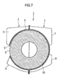
- the staple case 1 is split into two at the center of the front and rear direction, a front side case half 2 and a rear side case half 3 are molded by means of blow molding or vacuum molding by using a sheet material such as a calcium carbonate-containing polypropylene sheet or the like, and the roll staple S is contained in the hollow columnar roll staple containing chamber 4 formed by the front side case half 2 and the rear side case half 3, and flange portions 2a and 3a of the front side case half 2 and the rear side case half 3 are bonded to each other.
- a staple pull-out opening 9 is opened, and the roll staple S is pulled out through the staple pull-out opening 9.
- This staple pull-out opening 9 may be formed by forming perforations or thinned portions on the staple case 1 and removing these before use.
- the front surfaces of the front side lower cushion portions 6 below the staple pull-out opening 9 are sloped down to the front side from the staple pull-out opening 9 so that a staple is smoothly pulled out.
- a rectangular opening 10 is formed in the bottom face of the roll staple containing chamber portion of the rear side case half 3.
- This opening 10 may also be formed by forming a weak portion such as perforations or thinned portions on the staple case and removing this portion before use.
- Fig. 8A and Fig. 8B show a staple cartridge C, wherein the staple containing chamber 11 of the staple cartridge C has a shape and dimensions suitable for the staple case 1.
- the inner bottom surface is formed into a concave surface matching the shapes of the cushion portions 6 and 8 of the staple case 1.
- An electric stapler (not shown) has a staple forming and driving means to be driven by a motor, a cartridge chamber in which a cartridge C containing a staple case is loaded, and a staple clinch mechanism, wherein a staple feeding roller 12 is provided below the cartridge chamber.
- the staple feeding roller 12 comes into contact with the roll staple S through the lower face opening 10 of the staple case 1.
- the electric stapler is provided with a cartridge detection sensor.
- the staple feeding roller 12 starts and rotates the roll staple S counterclockwise in the figures.
- the leading edge of the roll staple S is pushed out of the staple pull-out opening 9, and fed to the driver path on the fore end through the cushion portions 6 on the front lower side and the guide portion 13 of the staple cartridge C, and formed into a C shape by a forming plate of the electric stapler so as to enable stapling.
- an electric stapler is described as an example, however, a manual stapler that has a cartridge chamber and a staple feed means, etc., and carries out manual forming and stapling is also possible.
- Fig. 9 shows a second embodiment of the invention, wherein a staple case 21 is provided with a staple pull-out opening 23 in the bottom face of a front side case half 22, and as in the case with the above-mentioned embodiment, a staple feeding roller 12 is brought into contact with the roll staple S through an opening 25 opened in the bottom face of a rear side case half 24.
- the roll staple S is driven to rotate clockwise in the figure, whereby the leading edge of the roll staple S is pushed forward out of the staple pull-out opening 23, and a staple is automatically set in the staple cartridge.
- the external shapes of the staple cases 1 and 21 are shaped by providing a cylindrical shape fitting the outer circumference of the cylindrical roll staple with cushion portions. However, it is also possible that they are shaped into cylinders provided with substantially even cushion portions on the outer circumference of the roll staple containing chamber.
- Fig. 10 shows a third embodiment of the invention, wherein the staple chamber 32 of the staple case 31 is formed so that its upper portion is curved so as to fit the outer circumference of the roll staple and its lower portion is squared for stability. Inside the lower portion, receivers 33 with curved surfaces for supporting the roll staple are formed. In the figure, on the lower right of the staple case 31, an opening 34 for receiving a staple feeding roller 12 is formed. On the lower left, a staple pull-out opening 35 is formed.
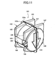
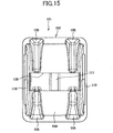
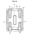
- Fig. 11 shows an empty staple case 101 according to a fourth embodiment of the invention
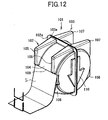
- Fig. 12 shows a condition where the leading edge of the roll staple S contained in the staple case 101 is pulled out.
- the staple case 101 is split vertically at the center of the cross direction, and a front side case half 102 and a rear side case half 103 are molded by means of blow molding or vacuum molding by using a sheet material such as a calcium carbonate-containing polypropylene sheet or the like.
- Flange portions 102a and 103a of the front side case half 102 and the rear side case half 103 are bonded after containing the roll staple S inside the hollow cylindrical roll staple containing chamber 104 formed of the front side case half 102 and the rear side case half 103.
- hollow cushion portions 105, 106, 107, and 108 substantially squared as a whole are formed.
- the squared cushion portions 105, 106, 107, and 108 serve as packing materials, and prevent the staple case 101 from moving within the paper box.
- the squared cushion portions 105, 106, 107, and 108 prevent the roll staple S from being broken by absorbing the impact.
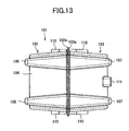
- the upper surfaces of the upper cushion portions 105 and 107 and the bottom surfaces of the lower cushion portions 106 and 108 are made different from each other.
- the bottom surfaces of the lower cushion portions 106 and 108 have arcs with a curvature smaller than that of the upper surfaces of the upper cushion portions 105 and 107.
- a staple pull-out opening 109 is opened, and the roll staple S is pulled out through the staple pull-out opening 109.
- This staple pull-out opening 109 may be formed by forming perforations or thinned portions on the staple case 101 and removing these portions before use.
- the front surfaces of the front side lower cushion portions 106 below the staple pull-out opening 109 are sloped down to the front side from the staple pull-out opening 109 so that the staple is smoothly pulled out.
- a downward arrow mark is relief-engraved to indicate the direction of insertion into a staple cartridge.
- a vertically long cushion portion 111 that performs both the front and rear judging marking function and the erroneous insertion prevention function is provided so that the front face and the back face are different in shape from each other.
- the staple case 101 is inserted into a staple cartridge is described above, and as a matter of course, it is also possible that the staple case 101 is directly inserted into a staple containing chamber of a stapler. Although illustration is omitted; by forming a weak portion such as perforations or thinned portions, etc., on the flange portions 102a and 103a at the bonded portions between the front side case half 102 and the rear side case half 103 of the staple case 101, for example, when the roll staple is broken or defective, the roll staple S can be taken out by splitting the staple case 101 into the front side case half 102 and the rear side case half 103 and can be disposed separately from the staple case 101.
- a weak portion such as perforations or thinned portions, etc.
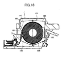
- Fig. 18 shows a condition where the staple case 101 is loaded in the staple cartridge C, and the inside of the staple cartridge C has a shape and dimensions suitable for the staple case 101, so that the staple case 101 can be directly loaded by opening the upper cover without denuding the roll staple, and this makes loading extremely easy.
- the bottom surface is concaved so as to match the shapes of the lower cushion portions 106 and 108, and at the horizontal center of the front side wall face of the staple containing chamber, a projection 112 for preventing erroneous insertion is provided. Therefore, when the staple case 101 is inserted upside down, the staple case 101 is not completely inserted into the staple containing chamber, and the upper cover of the staple cartridge C cannot be closed. When the staple case 101 is inserted by reversing its front and rear sides, the cushion portion 111 at the center of the back face of the staple case 101 comes into contact with the projection 112 and makes insertion impossible, whereby erroneous insertion is prevented.
- Fig. 19 shows a fifth embodiment of the invention, which is a staple case 121 containing layered sheet staples, wherein the four corners are protruded to form cushion portions 122, and cushion portions 123 formed of flanges of case halves are formed on the upper face and the bottom face.
- a pressing portion (not shown) provided on a stapler in which the staples are loaded is inserted, and the sheet staple pull-out opening 125 appears by removing the section surrounded by the weak portion such as perforations.
- This staple case can also prevent sheet staples contained therein from falling into pieces when the case is dropped or transported, and can be loaded in a stapler together with the whole staple case 121.
- the staple case of the invention is a case containing a roll staple inside, and it is not necessary to bundle the roll staple with tape, so that removal of the tape is unnecessary when using, and the roll staple is contained in the case and prevented from being unrolled when it is dropped.
- the staple case has no guide path or extending part for guiding the contained roll staple to a stapler, so that the staple case is manufactured by means of blow molding or vacuum molding that keep costs low, and after the staples are used up, the case as a single material is only disposed, and it can be easily incinerated, so that the staple case saves resources and reduces environmental load.
- the roll staple can be fed from the inside of the staple case to the fore end of the staple case by the staple feed mechanism of a stapler, and therefore, the conventional operation for manually pulling the roll staple out and setting it becomes unnecessary, whereby staple supply operation becomes easy.
- the staple case of the invention is provided with a staple pull-out opening and can be directly loaded in a staple cartridge, so that the operation for supplying staples to the staple cartridge is extremely easy, and it is not necessary to denude the roll staple, so that the fear of breakage of the roll staple when supplying staples is eliminated.
- the cushion portions are provided on the corners of the staple case and roughly squared, so that it is not necessary to put packing in the package box, and this provides effects of cost reduction and resource saving.
- the front face and the back face, and the upper face and the bottom face of the staple case are made different in shape from each other, whereby the staple case is prevented from being inserted in the wrong direction into the case containing portion of a cartridge, so that the staple supply operation becomes easy and insertion errors can be prevented.
Landscapes
- Engineering & Computer Science (AREA)
- Mechanical Engineering (AREA)
- Life Sciences & Earth Sciences (AREA)
- Forests & Forestry (AREA)
- Portable Nailing Machines And Staplers (AREA)
- Cartons (AREA)
Abstract
Description
Claims (9)
- A staple case that contains a roll staple formed by connecting unformed staples in a roll shape.
- The staple case according to Claim 1, comprising:a pull-out opening through which the roll staple contained in the staple case is pulled out.
- The staple case according to Claim 1, comprising:an opening, formed at a part of the staple case facing a circumferential surface of the contained roll staple, through which a member for rotating the roll staple faces.
- A staple case for containing staples used for a stapler comprising:a cushion portion provided on the staple case.
- A staple case for containing staples used for a stapler, comprising:a portion for positioning in a containing chamber.
- A staple case for containing staples used for a stapler, comprising:a guide portion for guiding the staple case to a containing chamber.
- The staple case according to any one of Claims 1, 4, 5, and 6, wherein the staple case is formed by joining case halves molded by being split into two.
- The staple case according to Claim 7, wherein a weak portion is provided on a joint between the two case halves so that the two case halves can be split.
- A staple case for containing staples used for a stapler, wherein a mark indicating the direction of insertion into the stapler is shown on the side face, at least one of the pair of upper and bottom faces and the pair of front and back faces are made different from each other to limit the direction of insertion into a stapler to one direction.
Applications Claiming Priority (5)
| Application Number | Priority Date | Filing Date | Title |
|---|---|---|---|
| JP2002296679A JP4154988B2 (en) | 2002-10-09 | 2002-10-09 | Staple case |
| JP2002296674 | 2002-10-09 | ||
| JP2002296679 | 2002-10-09 | ||
| JP2002296674A JP4154987B2 (en) | 2002-10-09 | 2002-10-09 | Staple case |
| PCT/JP2003/012843 WO2004033157A1 (en) | 2002-10-09 | 2003-10-07 | Staple case |
Publications (3)
| Publication Number | Publication Date |
|---|---|
| EP1550531A1 true EP1550531A1 (en) | 2005-07-06 |
| EP1550531A4 EP1550531A4 (en) | 2008-12-10 |
| EP1550531B1 EP1550531B1 (en) | 2018-04-25 |
Family
ID=32095419
Family Applications (1)
| Application Number | Title | Priority Date | Filing Date |
|---|---|---|---|
| EP03758715.1A Expired - Lifetime EP1550531B1 (en) | 2002-10-09 | 2003-10-07 | Staple case |
Country Status (5)
| Country | Link |
|---|---|
| US (1) | US7497329B2 (en) |
| EP (1) | EP1550531B1 (en) |
| AU (1) | AU2003275545A1 (en) |
| TW (1) | TWI236406B (en) |
| WO (1) | WO2004033157A1 (en) |
Cited By (1)
| Publication number | Priority date | Publication date | Assignee | Title |
|---|---|---|---|---|
| EP2172310A1 (en) * | 2003-12-04 | 2010-04-07 | Max Co., Ltd. | Stapling apparatus |
Families Citing this family (1)
| Publication number | Priority date | Publication date | Assignee | Title |
|---|---|---|---|---|
| JP4013255B2 (en) * | 2003-08-29 | 2007-11-28 | マックス株式会社 | Staple refill |
Family Cites Families (18)
| Publication number | Priority date | Publication date | Assignee | Title |
|---|---|---|---|---|
| US3009618A (en) * | 1956-01-27 | 1961-11-21 | Inv S Man Corp | Staple element cartridge |
| US3602414A (en) * | 1969-01-14 | 1971-08-31 | Swingline Inc | Dispenser for belt-type staples |
| EP0059713B1 (en) | 1980-09-17 | 1986-06-11 | Swingline, Inc. | Staple forming and driving machine and method |
| US5273199A (en) * | 1990-03-07 | 1993-12-28 | Xerox Corporation | Staple cartridge |
| SE9201230L (en) * | 1992-04-16 | 1993-05-17 | Isaberg Ab | CASE FOR USE IN A PAPER |
| JP2689840B2 (en) | 1993-01-19 | 1997-12-10 | マックス株式会社 | Staple cartridge and staple sheet pack |
| JP3355514B2 (en) | 1995-11-16 | 2002-12-09 | ニスカ株式会社 | Staplers and staple cartridges |
| US6039230A (en) * | 1997-11-19 | 2000-03-21 | Max Co., Ltd. | Roll staple and staple cartridge storing the same |
| JP2000167782A (en) | 1998-12-02 | 2000-06-20 | Nisca Corp | Stapler needle package and stapler device |
| JP3514163B2 (en) * | 1999-04-16 | 2004-03-31 | マックス株式会社 | Roll staples |
| JP2000354980A (en) | 1999-06-14 | 2000-12-26 | Max Co Ltd | Staple cartridge |
| JP2001347472A (en) * | 2000-06-05 | 2001-12-18 | Nisca Corp | Stapler device |
| JP4514286B2 (en) | 2000-06-05 | 2010-07-28 | ニスカ株式会社 | Staple needle storage cartridge |
| US6899259B2 (en) | 2000-07-26 | 2005-05-31 | Max Co., Ltd. | Roll staple cartridge |
| JP4802411B2 (en) | 2000-07-26 | 2011-10-26 | マックス株式会社 | Roll staple cartridge |
| JP2002200575A (en) * | 2000-12-28 | 2002-07-16 | Nisca Corp | Staple cartridge and stapler provided with the same |
| JP4857504B2 (en) * | 2001-09-10 | 2012-01-18 | マックス株式会社 | Electric stapler staple detection mechanism |
| USD504295S1 (en) * | 2002-01-31 | 2005-04-26 | Max Co., Ltd. | Staple cartridge |
-
2003
- 2003-10-07 TW TW092127757A patent/TWI236406B/en not_active IP Right Cessation
- 2003-10-07 US US10/530,563 patent/US7497329B2/en not_active Expired - Lifetime
- 2003-10-07 AU AU2003275545A patent/AU2003275545A1/en not_active Abandoned
- 2003-10-07 WO PCT/JP2003/012843 patent/WO2004033157A1/en not_active Ceased
- 2003-10-07 EP EP03758715.1A patent/EP1550531B1/en not_active Expired - Lifetime
Cited By (2)
| Publication number | Priority date | Publication date | Assignee | Title |
|---|---|---|---|---|
| EP2172310A1 (en) * | 2003-12-04 | 2010-04-07 | Max Co., Ltd. | Stapling apparatus |
| EP1690639B1 (en) * | 2003-12-04 | 2011-08-24 | Max Co., Ltd. | Staple device |
Also Published As
| Publication number | Publication date |
|---|---|
| US7497329B2 (en) | 2009-03-03 |
| US20060054653A1 (en) | 2006-03-16 |
| EP1550531A4 (en) | 2008-12-10 |
| WO2004033157A1 (en) | 2004-04-22 |
| AU2003275545A1 (en) | 2004-05-04 |
| TWI236406B (en) | 2005-07-21 |
| EP1550531B1 (en) | 2018-04-25 |
| TW200413142A (en) | 2004-08-01 |
Similar Documents
| Publication | Publication Date | Title |
|---|---|---|
| JP3967078B2 (en) | Powder container and method for assembling the container | |
| EP1603752B1 (en) | Ink bag and ink cartridge comprising the ink bag | |
| US20060002743A1 (en) | Apparatuses for image forming capable of effectively conveying developer therefrom and a method of effectively forming a reinforcing member adhering to the apparatuses | |
| EP1793283A1 (en) | Powder container and toner replenishing device and image forming apparatus including the same | |
| JP7306559B2 (en) | Refill | |
| US10434788B2 (en) | Liquid storage unit | |
| US7497329B2 (en) | Staple case | |
| WO2003018267A1 (en) | Staple cartridge of electric stapler | |
| JPH09301434A (en) | Packaging box | |
| US20180265245A1 (en) | Packaging box and packaging form of toner cartridge | |
| JP4485937B2 (en) | Developer container and image forming apparatus | |
| CN100374251C (en) | staple case | |
| JP2004130425A (en) | Staple housing | |
| IT202100028475A1 (en) | Apparatus and manufacturing process of a disposable inhaler | |
| WO2006095499A1 (en) | Packaging material container | |
| JP3942782B2 (en) | Transport system for ultra-thin plastic liquid containers | |
| US6993265B2 (en) | Seal for toner cartridge assembly | |
| JP4364500B2 (en) | Card storage cartridge | |
| JPS6015331A (en) | Sheet cartridge | |
| JP2020111340A (en) | Cushioning member, package | |
| AU2006200057A1 (en) | Device for separating labels stacked in a feeder | |
| JP2004149170A (en) | Sheet tray for parts for image forming equipment | |
| JP3122572U (en) | Toner cartridge storage container | |
| JPH11184228A (en) | Toner supply container | |
| JP2004115084A (en) | Tape-shaped carrier for image forming device parts |
Legal Events
| Date | Code | Title | Description |
|---|---|---|---|
| PUAI | Public reference made under article 153(3) epc to a published international application that has entered the european phase |
Free format text: ORIGINAL CODE: 0009012 |
|
| 17P | Request for examination filed |
Effective date: 20050407 |
|
| AK | Designated contracting states |
Kind code of ref document: A1 Designated state(s): AT BE BG CH CY CZ DE DK EE ES FI FR GB GR HU IE IT LI LU MC NL PT RO SE SI SK TR |
|
| AX | Request for extension of the european patent |
Extension state: AL LT LV MK |
|
| DAX | Request for extension of the european patent (deleted) | ||
| RBV | Designated contracting states (corrected) |
Designated state(s): DE FR GB NL |
|
| A4 | Supplementary search report drawn up and despatched |
Effective date: 20081112 |
|
| 17Q | First examination report despatched |
Effective date: 20090326 |
|
| REG | Reference to a national code |
Ref country code: DE Ref legal event code: R079 Ref document number: 60351147 Country of ref document: DE Free format text: PREVIOUS MAIN CLASS: B25C0005160000 Ipc: B27F0007380000 |
|
| RIC1 | Information provided on ipc code assigned before grant |
Ipc: B27F 7/38 20060101AFI20170510BHEP |
|
| GRAP | Despatch of communication of intention to grant a patent |
Free format text: ORIGINAL CODE: EPIDOSNIGR1 |
|
| INTG | Intention to grant announced |
Effective date: 20170720 |
|
| GRAJ | Information related to disapproval of communication of intention to grant by the applicant or resumption of examination proceedings by the epo deleted |
Free format text: ORIGINAL CODE: EPIDOSDIGR1 |
|
| INTC | Intention to grant announced (deleted) | ||
| GRAP | Despatch of communication of intention to grant a patent |
Free format text: ORIGINAL CODE: EPIDOSNIGR1 |
|
| INTG | Intention to grant announced |
Effective date: 20171107 |
|
| GRAA | (expected) grant |
Free format text: ORIGINAL CODE: 0009210 |
|
| GRAS | Grant fee paid |
Free format text: ORIGINAL CODE: EPIDOSNIGR3 |
|
| RIN1 | Information on inventor provided before grant (corrected) |
Inventor name: SAKATA, TOMOAKI Inventor name: HASEGAWA, TAKAO |
|
| AK | Designated contracting states |
Kind code of ref document: B1 Designated state(s): DE FR GB NL |
|
| REG | Reference to a national code |
Ref country code: GB Ref legal event code: FG4D |
|
| REG | Reference to a national code |
Ref country code: DE Ref legal event code: R096 Ref document number: 60351147 Country of ref document: DE |
|
| REG | Reference to a national code |
Ref country code: NL Ref legal event code: MP Effective date: 20180425 |
|
| PG25 | Lapsed in a contracting state [announced via postgrant information from national office to epo] |
Ref country code: NL Free format text: LAPSE BECAUSE OF FAILURE TO SUBMIT A TRANSLATION OF THE DESCRIPTION OR TO PAY THE FEE WITHIN THE PRESCRIBED TIME-LIMIT Effective date: 20180425 |
|
| REG | Reference to a national code |
Ref country code: FR Ref legal event code: PLFP Year of fee payment: 16 |
|
| REG | Reference to a national code |
Ref country code: DE Ref legal event code: R097 Ref document number: 60351147 Country of ref document: DE |
|
| PLBE | No opposition filed within time limit |
Free format text: ORIGINAL CODE: 0009261 |
|
| STAA | Information on the status of an ep patent application or granted ep patent |
Free format text: STATUS: NO OPPOSITION FILED WITHIN TIME LIMIT |
|
| 26N | No opposition filed |
Effective date: 20190128 |
|
| PGFP | Annual fee paid to national office [announced via postgrant information from national office to epo] |
Ref country code: FR Payment date: 20200914 Year of fee payment: 18 Ref country code: GB Payment date: 20200930 Year of fee payment: 18 |
|
| PGFP | Annual fee paid to national office [announced via postgrant information from national office to epo] |
Ref country code: DE Payment date: 20200922 Year of fee payment: 18 |
|
| REG | Reference to a national code |
Ref country code: DE Ref legal event code: R119 Ref document number: 60351147 Country of ref document: DE |
|
| GBPC | Gb: european patent ceased through non-payment of renewal fee |
Effective date: 20211007 |
|
| PG25 | Lapsed in a contracting state [announced via postgrant information from national office to epo] |
Ref country code: GB Free format text: LAPSE BECAUSE OF NON-PAYMENT OF DUE FEES Effective date: 20211007 Ref country code: DE Free format text: LAPSE BECAUSE OF NON-PAYMENT OF DUE FEES Effective date: 20220503 |
|
| PG25 | Lapsed in a contracting state [announced via postgrant information from national office to epo] |
Ref country code: FR Free format text: LAPSE BECAUSE OF NON-PAYMENT OF DUE FEES Effective date: 20211031 |