EP1550417B1 - Vorrichtung zum zusammendrücken eines Urethralstents - Google Patents
Vorrichtung zum zusammendrücken eines Urethralstents Download PDFInfo
- Publication number
- EP1550417B1 EP1550417B1 EP04258083A EP04258083A EP1550417B1 EP 1550417 B1 EP1550417 B1 EP 1550417B1 EP 04258083 A EP04258083 A EP 04258083A EP 04258083 A EP04258083 A EP 04258083A EP 1550417 B1 EP1550417 B1 EP 1550417B1
- Authority
- EP
- European Patent Office
- Prior art keywords
- stent
- mandrel
- protrusion
- tab
- compressor
- Prior art date
- Legal status (The legal status is an assumption and is not a legal conclusion. Google has not performed a legal analysis and makes no representation as to the accuracy of the status listed.)
- Expired - Lifetime
Links
Images

Classifications
-
- A—HUMAN NECESSITIES
- A61—MEDICAL OR VETERINARY SCIENCE; HYGIENE
- A61M—DEVICES FOR INTRODUCING MEDIA INTO, OR ONTO, THE BODY; DEVICES FOR TRANSDUCING BODY MEDIA OR FOR TAKING MEDIA FROM THE BODY; DEVICES FOR PRODUCING OR ENDING SLEEP OR STUPOR
- A61M27/00—Drainage appliance for wounds or the like, i.e. wound drains, implanted drains
- A61M27/002—Implant devices for drainage of body fluids from one part of the body to another
- A61M27/008—Implant devices for drainage of body fluids from one part of the body to another pre-shaped, for use in the urethral or ureteral tract
-
- A—HUMAN NECESSITIES
- A61—MEDICAL OR VETERINARY SCIENCE; HYGIENE
- A61F—FILTERS IMPLANTABLE INTO BLOOD VESSELS; PROSTHESES; DEVICES PROVIDING PATENCY TO, OR PREVENTING COLLAPSING OF, TUBULAR STRUCTURES OF THE BODY, e.g. STENTS; ORTHOPAEDIC, NURSING OR CONTRACEPTIVE DEVICES; FOMENTATION; TREATMENT OR PROTECTION OF EYES OR EARS; BANDAGES, DRESSINGS OR ABSORBENT PADS; FIRST-AID KITS
- A61F2/00—Filters implantable into blood vessels; Prostheses, i.e. artificial substitutes or replacements for parts of the body; Appliances for connecting them with the body; Devices providing patency to, or preventing collapsing of, tubular structures of the body, e.g. stents
- A61F2/95—Instruments specially adapted for placement or removal of stents or stent-grafts
- A61F2/9522—Means for mounting a stent or stent-graft onto or into a placement instrument
-
- A—HUMAN NECESSITIES
- A61—MEDICAL OR VETERINARY SCIENCE; HYGIENE
- A61F—FILTERS IMPLANTABLE INTO BLOOD VESSELS; PROSTHESES; DEVICES PROVIDING PATENCY TO, OR PREVENTING COLLAPSING OF, TUBULAR STRUCTURES OF THE BODY, e.g. STENTS; ORTHOPAEDIC, NURSING OR CONTRACEPTIVE DEVICES; FOMENTATION; TREATMENT OR PROTECTION OF EYES OR EARS; BANDAGES, DRESSINGS OR ABSORBENT PADS; FIRST-AID KITS
- A61F2/00—Filters implantable into blood vessels; Prostheses, i.e. artificial substitutes or replacements for parts of the body; Appliances for connecting them with the body; Devices providing patency to, or preventing collapsing of, tubular structures of the body, e.g. stents
- A61F2/95—Instruments specially adapted for placement or removal of stents or stent-grafts
- A61F2/9522—Means for mounting a stent or stent-graft onto or into a placement instrument
- A61F2/9526—Means for mounting a stent or stent-graft onto or into a placement instrument using a mandrel
-
- A—HUMAN NECESSITIES
- A61—MEDICAL OR VETERINARY SCIENCE; HYGIENE
- A61M—DEVICES FOR INTRODUCING MEDIA INTO, OR ONTO, THE BODY; DEVICES FOR TRANSDUCING BODY MEDIA OR FOR TAKING MEDIA FROM THE BODY; DEVICES FOR PRODUCING OR ENDING SLEEP OR STUPOR
- A61M25/00—Catheters; Hollow probes
- A61M25/01—Introducing, guiding, advancing, emplacing or holding catheters
-
- A—HUMAN NECESSITIES
- A61—MEDICAL OR VETERINARY SCIENCE; HYGIENE
- A61F—FILTERS IMPLANTABLE INTO BLOOD VESSELS; PROSTHESES; DEVICES PROVIDING PATENCY TO, OR PREVENTING COLLAPSING OF, TUBULAR STRUCTURES OF THE BODY, e.g. STENTS; ORTHOPAEDIC, NURSING OR CONTRACEPTIVE DEVICES; FOMENTATION; TREATMENT OR PROTECTION OF EYES OR EARS; BANDAGES, DRESSINGS OR ABSORBENT PADS; FIRST-AID KITS
- A61F2/00—Filters implantable into blood vessels; Prostheses, i.e. artificial substitutes or replacements for parts of the body; Appliances for connecting them with the body; Devices providing patency to, or preventing collapsing of, tubular structures of the body, e.g. stents
- A61F2/02—Prostheses implantable into the body
- A61F2/04—Hollow or tubular parts of organs, e.g. bladders, tracheae, bronchi or bile ducts
- A61F2002/047—Urethrae
-
- Y—GENERAL TAGGING OF NEW TECHNOLOGICAL DEVELOPMENTS; GENERAL TAGGING OF CROSS-SECTIONAL TECHNOLOGIES SPANNING OVER SEVERAL SECTIONS OF THE IPC; TECHNICAL SUBJECTS COVERED BY FORMER USPC CROSS-REFERENCE ART COLLECTIONS [XRACs] AND DIGESTS
- Y10—TECHNICAL SUBJECTS COVERED BY FORMER USPC
- Y10T—TECHNICAL SUBJECTS COVERED BY FORMER US CLASSIFICATION
- Y10T29/00—Metal working
- Y10T29/49—Method of mechanical manufacture
- Y10T29/49826—Assembling or joining
- Y10T29/49908—Joining by deforming
- Y10T29/49925—Inward deformation of aperture or hollow body wall
- Y10T29/49927—Hollow body is axially joined cup or tube
Definitions
- the present invention relates to apparatus used for compressing a coiled stent and more particularly, for compressing a specific end portion of a stent prior to insertion either into an insertion apparatus or directly within the body.
- Lower urinary tract symptoms common among older men, include a variety of disorders that can lead to urinary retention and complications resulting from retention. Some of the conditions falling under a LUTS diagnosis include an enlarged prostate, BPH, and bladder outlet obstruction.
- the constriction of the urethra due to prostatic enlargement can be treated by the implantation of a prostatic urethral stent.
- the stent serves to hold the prostatic urethra open to allow urination. This is typically an interim solution used before or after corrective treatment, e.g., a stent may be implanted after radiation treatments, thermal therapy or cryosurgery to keep the urethra open while post-treatment edema subsides. In some instances, a stent may be implanted as a primary treatment.
- urethral stents are tubular in shape and may be in the form of a solid tube, coiled wire, ribbon or mesh, or formed from braided filaments.
- Coiled stents may be designed to have at least a portion thereof with outer diameter equal to or larger than the average urethral lumen diameter, such that when expanded, the stent frictionally engages the urethra into which it has been inserted.
- the larger diameter coils of such stents need to be radially compressed prior to insertion into a stent delivery system, e.g., a catheter sheath, or within the urethra.
- urethral stents After being positioned in the urethra, urethral stents are radially expanded into their final shape, typically by thermal or mechanical means, or, in the case of self-expanding stents, allowed to elastically expand when a sheath or other restraining means is removed.
- Brenneman et al. U. S. Pat. No. 5,160,341 disclose a device including a retractable sheath surrounding a rotatable rod journaled in a stationary tubular bushing. One end of the stent is mounted on the rod while the other end of the stent is fixed to the bushing so that relative rotation of the rod and bushing compresses the entire stent by coiling it more tightly. After insertion within the body, the rod and bushing are then rotated in the opposite direction to uncoil the stent to its original diameter. A shearing sleeve with a shearing edge is advanced between the rod and bushing to sever the stent from its attachment to the bushing and the rod.
- both ends of the stent are used to engage the urethra and the diameter along the entire stent length is reduced.
- Reduction of stent diameter results in a concomitant increase in length in the reduced region.
- Reduction of stent diameter along the entire stent length will therefore result in significant length increases upon diameter reduction, sizing, bunching, and consequent placement issues within the anatomy.
- only an end portion of the stent has a varying diameter. It is undesirable, particularly with polymer stents, to expose a stent to unnecessary forces due to risk of plastic deformation or creep. There are also risks associated with introducing a shearing sleeve with shearing edge within the urethra e.g. breakage, contamination and/or injury.
- the cut ends of the stent are sharp and pose a risk of penetrating the urethra.
- Yachia et al. U. S. Pat. No. 5,246,445 disclose stents with non-uniform windings such that one or more coils along the length of the stent bulge out circumferentially.
- An apparatus is disclosed which fixes either end of the stent and through torquing action, radially compresses the bulges.
- the entire length of the stent is reduced by rotating the ends of the helical spiral in opposite directions.
- a small hook, ring, or ball is provided at each end of the stent for grasping it.
- Limon U. S. Pat. No. 5,476,505 discloses a stent delivery system including a catheter formed from coaxially arranged inner and outer flexible shafts, the distal ends of which have slots or apertures to engage the ends of a coiled stent. The entire length of the stent is effected by inducing tighter coiling. The device is counter-rotated to expand and release the stent.
- Mikus et al. discloses a stent made from a shape memory alloy and a delivery device for placing the stent into the prostatic urethra.
- the delivery device (catheter) has three coaxial hollow members that are rotatable and slideable relative to each other, viz., an inner tube, an outer catheter tube and a sheath.
- the stent is wrapped around a portion (loading zone) of the inner tube which extends beyond the outer catheter tube.
- An annular recess is provided on the inner tube that receives a turn of the stent at one end thereof.
- An annular recess or notch is provided on the outer catheter tube for receiving a turn of the stent at the opposite end thereof.
- the stent has holes in each end thereof.
- the holes receive pull wires, respectively, which extend through lumens in the inner tube and outer catheter tube, respectively, to retain the ends of the stent in the annular recesses, respectively.
- the inner tube and outer catheter tube are rotated relative to each other in a direction resulting in the unwinding of the stent, causing the stent to increase in diameter. Exposure to the temperature of the body and/or a warm fluid discharged on the stent, may also induce the stent to transition to the austenite state further causing an increase in diameter.
- the pull wires are pulled, releasing their hold on the holes in the ends of the stent and allowing the stent to fully expand to contact the prostatic urethra and to disconnect from the insertion device, which may then be withdrawn from the urethra.
- Such a device can be used to facilitate placement of the stent either within a secondary insertion tool or directly within the body.
- the limitations of prior art apparatus for compressing stents are overcome by the present invention which includes an apparatus for compressing a coiled stent having at least one protrusion as defined in claim 1.
- the apparatus has a mandrel insertable into a lumen of the stent for holding the stent and a coil compressor coupled to the mandrel.
- the mandrel is rotatable on an axis relative to the coil compressor and the coil compressor has a tab extending therefrom towards the mandrel. The tab presses the protrusion of the stent inwardly toward the lumen of the stent when the mandrel is rotated relative to the coil compressor.
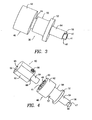
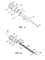
- FIGS 1 through 9 show a stent reducer 10 for use in radially compressing selected larger diameter, radially-expanded coils 86 (See Figure 6 ) of a coiled stent 80 without radially compressing the entire stent along its length.
- Stent 80 has a generally cylindrical coil shape, such as the stent described in EP-A-1 491 221 .
- the stent 80 has a distal end 84 and a proximal end 82. Note that “proximal” and “distal” are reversed from the directionality of the stent reducer 10, because the convention applied to the stent 80 is relative to the bladder of the patient in which the stent 80 is placed.
- the diameter of the distal end 84 is greater than the remainder of the stent 80 due to radially expanded coil 86. While more than one complete turn of the coiled stent 80 is enlarged in Fig. 6 , less than or greater than one complete turn of the stent 80 may be enlarged.
- stent reducer 10 has a mandrel 20 with a tapering distal end 22 which facilitates the insertion of the mandrel 20 into the lumen 81 (See Fig. 6 ) of the coiled stent 80, a proximal end 24 and a stent fixation zone 26.
- the diameter of the stent fixation zone 26 is the same as, or slightly larger than, the inner diameter of at least some portion of the stent 80, so that an interference fit is established between stent 80 and stent fixation zone 26 when the mandrel 20 is inserted into the stent 80.
- the stent 80 can be rotated on the mandrel manually with minimal resistance.
- the mandrel 20 may be one-piece or in a plurality of modular sections to accommodate various stent 80 sizes.
- the modular sections can be connected by conventional means, e.g., threads, snap-fit coupling, etc.
- FIG 2 shows an exploded view of latch assembly 30, which includes latch knob 40 and latch collar 50.
- the latch knob 40 has a grip portion 42, a hub portion 44 with a slot 45, and a post portion 46 with a relief 47.
- the latch knob 40 has an axial cannulation 41 into which the post 64 of mandrel knob 60 inserts and which also allows the mandrel 20 to extend through the latch knob 40.
- the latch knob 40 has ball plunger detents 49 on its proximal end (see Figure 4 ).
- Latch collar 50 has a flange 52 against which the fingers of a user may press to control the position thereof.
- a pin 57 extends through hole 58 after the latch collar 50 is slidably and coaxially slipped onto the hub portion 44, the end of the pin 57 being accommodated in slot 45 and retaining the latch collar 50 on the latch knob 40 while permitting relative movement to the extent of the length of the slot 45.
- the latch collar 50 has a stepped internal bore 59 having internal dimensions approximating the external dimensions of the hub and post portions 44, 46 of the latch knob 40.
- a sleeve 54 extends from the flange 52 and has a distal tab 56 for contacting and compressing the stent 80.
- tab 56 when assembled to form latch assembly 30, tab 56 overhangs relief 47.
- the length of slot 45 limits the range of axial motion of latch knob 40 in the distal direction to the point where tab 56 at least partially overhangs relief 47.
- Figure 4 shows mandrel knob 60, which has a grip portion 62 with a mandrel bore 65 for receiving proximal end 24 of mandrel 20 therein.
- the mandrel 20 is retained by a set screw (not shown) inserted into a threaded bore 66 and bearing upon the proximal end 24 thereof.
- a ball plunger 68 or similar spring-tape resilient member (not shown) is received within mating bore 69.
- Detents 49 are provided on a proximal surface 43 of latch knob 40 and receive the ball plunger 68 therein to control the axial rotation of mandrel knob 60 and mandrel 20 relative to the latch knob 40.
- Figure 4 shows the latch knob 40 withdrawn to a proximal position wherein the tab 56 is retracted from relief 47.
- Figure 5 shows the fully assembled stent reducer 10.
- the diameter of stent fixation zone 26 is approximately the same as the diameter of post portion 46. This prevents latch assembly 30 from sliding off of the mandrel 20.
- Figure 6 shows a stent 80 in position on the mandrel 20 of stent reducer 10 prior to compression of radially expanded coils 86 on the distal end 84 of the stent 80.
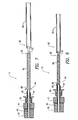
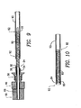
- Figure 7 through 10 show cross-sectional views of the stent reducer 10 and how it is used to reduce the diameter of the enlarged coils 86 at the distal end 84 of the stent 80, and load the stent 80 into a sheath 90.
- the mandrel 20 is inserted into the lumen of stent 80.
- the enlarged coils 86 of stent 80 distal end 84 are of a larger diameter than the remainder of the stent 80 and extend beyond the stent fixation zone 26 in the proximal direction.
- the latch collar 50 is positioned proximally on the latch knob 40 such that the tab 56 is retracted to a position removed from relief 47.
- Figure 8 shows the reduced distal end 84 of the stent 80 resulting from pushing the latch collar 50 forward, such that the tab 56 extends over an outer surface of the enlarged coil 86, capturing it between the tab 56 and the relief 47.
- the ball plunger 68 and ball plunger detents 49 ( Figure 4 ) provide controlled relative rotation defining discrete tightening steps to avoid overrotation of stent 80. Once the outer diameter of the enlarged coils 86 are reduced, the stent 80 may be inserted into the sheath 90.
- FIG. 10 shows a stent 80 in a sheath 90 after removal of the mandrel 20.
Landscapes
- Health & Medical Sciences (AREA)
- Engineering & Computer Science (AREA)
- Biomedical Technology (AREA)
- Life Sciences & Earth Sciences (AREA)
- Veterinary Medicine (AREA)
- Animal Behavior & Ethology (AREA)
- Heart & Thoracic Surgery (AREA)
- Public Health (AREA)
- General Health & Medical Sciences (AREA)
- Hematology (AREA)
- Anesthesiology (AREA)
- Vascular Medicine (AREA)
- Cardiology (AREA)
- Oral & Maxillofacial Surgery (AREA)
- Transplantation (AREA)
- Urology & Nephrology (AREA)
- Otolaryngology (AREA)
- Ophthalmology & Optometry (AREA)
- Biophysics (AREA)
- Pulmonology (AREA)
- Media Introduction/Drainage Providing Device (AREA)
- Prostheses (AREA)
- External Artificial Organs (AREA)
- Surgical Instruments (AREA)
Claims (12)
- Vorrichtung (10) zum Zusammendrücken eines Stents (80), der wenigstens einen Vorsprung (86) hat, wobei die Vorrichtung (10) aufweist:einen Dorn (20), der zum Halten des Stents (80) in ein Lumen (81) des Stents (80) einsetzbar ist; und gekennzeichnet ist durch:einer Vorsprung-Preßeinrichtung (30), der an den Dorn (20) gekoppelt ist, wobei der Dorn (20) relativ zu der Vorsprung-Preßeinrichtung (30) drehbar ist, wobei die Vorsprung-Preßeinrichtung (30) einen Ansatz (56) hat, der sich von diesem auf den Dorn (20) zu erstreckt, wobei der Ansatz (56) den wenigstens einen Vorsprung (86) des Stents nach innen zum Lumen (81) des Stents (80) drückt, wenn der Dorn (20) relativ zu der Vorsprung-Preßeinrichtung (30) gedreht wird.
- Vorrichtung (10) nach Anspruch 1, bei der sich der Dorn (20) koaxial durch die Vorsprung-Preßeinrichtung (30) erstreckt.
- Vorrichtung (10) nach Anspruch 1 oder Anspruch 2, weiter mit einem Knauf (60), der auf einem Ende (24) des Doms (20) abgeordnet ist, um beim Drehen des Doms (20) zu helfen und zum Halten der Vorsprung-Preßeinrichtung (30) auf dem Dorn.
- Vorrichtung (10) nach einem der Ansprüche 1 bis 3, bei der der Dorn (20) eine Fixier- oder Haltezone (26) für den Stent hat, mit einem Außendurchmesser, der an den Innendurchmesser wenigstens eines Teils des Lumens (81) des Stents (80) angenähert ist, und die reibschlüssig den Stent (80) hält, wenn der Stent (80) über der Fixier- oder Haltezone (26) für den Stent auf den Dorn (20) gebracht ist.
- Vorrichtung (10) nach Anspruch 4, bei der der Dorn (20) ein abgeschrägtes Ende (22) hat, das zu der Fixier- oder Haltezone (26) für den Stent führt, wobei das abgeschrägte Ende (22) beim Einführen des Domes (20) in das Lumen (81) des Stents (80) und beim Schieben des Stents auf die Fixier- oder Haltezone (26) für den Stent hilft.
- Vorrichtung (10) nach Anspruch 4 oder Anspruch 5, bei der die Vorsprung-Preßeinrichtung (30) zwischen dem Knauf (60) und der Fixier- oder Haltezone (26) für den Stent gefangen ist.
- Vorrichtung (10) nach Anspruch 6, bei der die Vorsprung-Preßeinrichtung (30) sowohl einen Griffbereich (42) mit einer Nabe (44) als auch einen Kragen (50) hat, wobei der Kragen (50) koaxial auf der Nabe (44) aufgenommen ist und den Ansatz (56) aufweist, der sich an einem distalen Ende von ihm erstreckt, wobei der Kragen (50) durch einen Stift (57), der sich durch ihn und in einen länglichen Schlitz (45) in der Welle (44) erstreckt, daran gehindert ist, sich relativ zu dem Griffbereich (42) zu drehen, wobei der Schlitz (45) und der Stift (57) den Kragen (50) auf eine teleskopische Bewegung auf der Nabe (44) entlang einem Bewegungsweg, der durch den Schlitz (45) begrenzt ist, einschränken und eine zurückgezogene Position und eine ausgerückte Position für den Ansatz (56) definieren.
- Vorrichtung (10) nach Anspruch 7, bei der der Kragen (50) einen Flansch (52) hat, der sich von diesem nach außen erstreckt, der für einen Benutzer zu greifen ist, um beim Ausrücken und Zurückziehen des Ansatzes (56) zu helfen.
- Vorrichtung (10) nach Anspruch 8, bei der der Griffbereich (42) eine hohle Säule (46) hat, die sich von der Nabe (44) erstreckt, wobei die Säule (46) einen Aussparungsschlitz (47) auf ihrem distalen Ende hat, wobei der Aussparungsschlitz (47) an der Säule (46) so angeordnet ist, daß er mit dem Ansatz (56) ausgerichtet ist, wenn der Ansatz (56) in der ausgerückten Position ist, wobei der Ansatz (56) den wenigstens einen Vorsprung (86) des Stents (80) zwischen dem Ansatz (56) und dem Aussparungsschlitz (47) einfängt, wenn die Vorrichtung (10) auf den wenigstens einen Vorsprung (86) drückt.
- Vorrichtung (10) nach Anspruch 9, weiter mit einer Kugel (68) -Rasten-Kopplung (49),die zwischen dem Griffbereich (42) und dem Knauf (60) angeordnet ist, wobei die Kugel-Rasten-Kopplung die relative Drehung zwischen dem Griffbereich (42) und dem Knauf (60) steuert.
- Vorrichtung (10) nach Anspruch 10, bei der der wenigstens eine Vorsprung (86) des Stents (80) wenigstens eine vergrößerte Spule (86) ist, die an einem Ende des Stents (80) angeordnet ist, wobei die Vorrichtung (10) die vergrößerte Spule (86) nach innen drückt, indem der Kragen (50) vor in die ausgerückte Position geschoben wird, um die vergrößerte Spule (86) zwischen dem Ansatz (56) und dem Aussparungsschlitz (47) einzufangen, und der Knauf (60) und der Dorn (20) relativ zu der Vorsprung-Preßeinrichtung (30) gedreht wird.
- Vorrichtung (10) nach Anspruch 11, weiter mit einer Hülse (54), die sich von dem Kragen (50) distal bezüglich des Flansches (52) erstreckt, wobei sich der Ansatz (56) von der Hülse (54) erstreckt.
Priority Applications (3)
| Application Number | Priority Date | Filing Date | Title |
|---|---|---|---|
| SI200431071T SI1550417T1 (sl) | 2003-12-29 | 2004-12-23 | Naprava za stiskanje uretralnega stenta |
| PL04258083T PL1550417T3 (pl) | 2003-12-29 | 2004-12-23 | Urządzenie do ściskania stentu do cewki moczowej |
| CY20091100313T CY1108901T1 (el) | 2003-12-29 | 2009-03-20 | Συσκευη για μια ουρηθραια αγγειακη ενδοαυλικη προθεση |
Applications Claiming Priority (2)
| Application Number | Priority Date | Filing Date | Title |
|---|---|---|---|
| US748059 | 2000-12-22 | ||
| US10/748,059 US7636998B2 (en) | 2003-12-29 | 2003-12-29 | Urethral stent reducer |
Publications (2)
| Publication Number | Publication Date |
|---|---|
| EP1550417A1 EP1550417A1 (de) | 2005-07-06 |
| EP1550417B1 true EP1550417B1 (de) | 2008-12-24 |
Family
ID=34574758
Family Applications (1)
| Application Number | Title | Priority Date | Filing Date |
|---|---|---|---|
| EP04258083A Expired - Lifetime EP1550417B1 (de) | 2003-12-29 | 2004-12-23 | Vorrichtung zum zusammendrücken eines Urethralstents |
Country Status (11)
| Country | Link |
|---|---|
| US (1) | US7636998B2 (de) |
| EP (1) | EP1550417B1 (de) |
| JP (1) | JP4624097B2 (de) |
| AT (1) | ATE418299T1 (de) |
| CY (1) | CY1108901T1 (de) |
| DE (1) | DE602004018606D1 (de) |
| DK (1) | DK1550417T3 (de) |
| ES (1) | ES2318247T3 (de) |
| PL (1) | PL1550417T3 (de) |
| PT (1) | PT1550417E (de) |
| SI (1) | SI1550417T1 (de) |
Families Citing this family (8)
| Publication number | Priority date | Publication date | Assignee | Title |
|---|---|---|---|---|
| US7765670B2 (en) * | 2004-08-13 | 2010-08-03 | Boston Scientific Scimed, Inc. | Method to simultaneously load and cover self expanding stents |
| US8453598B2 (en) | 2006-07-20 | 2013-06-04 | Abbott Cardiovascular Systems Inc. | Stent holding fixtures |
| US7972373B2 (en) * | 2007-12-19 | 2011-07-05 | Advanced Technologies And Regenerative Medicine, Llc | Balloon expandable bioabsorbable stent with a single stress concentration region interconnecting adjacent struts |
| US8348111B2 (en) * | 2008-10-01 | 2013-01-08 | Jac Products, Inc. | System and method for vehicle article carrier having stowable cross bars |
| US9017351B2 (en) * | 2010-06-29 | 2015-04-28 | Artventive Medical Group, Inc. | Reducing flow through a tubular structure |
| CA3078928A1 (en) | 2017-10-18 | 2019-04-25 | Edwards Lifesciences Corporation | Catheter assembly |
| WO2020072849A1 (en) | 2018-10-04 | 2020-04-09 | Voyager Therapeutics, Inc. | Methods for measuring the titer and potency of viral vector particles |
| CN114101504B (zh) * | 2021-10-15 | 2024-01-23 | 内蒙古工业大学 | 一种用于金属血管支架热定型的通用工装夹具 |
Family Cites Families (11)
| Publication number | Priority date | Publication date | Assignee | Title |
|---|---|---|---|---|
| SU1754094A1 (ru) | 1990-03-11 | 1992-08-15 | В.В.Емель нов.; ;. -.- | Внутрисосудистый каркас |
| IL94138A (en) * | 1990-04-19 | 1997-03-18 | Instent Inc | Device for the treatment of constricted fluid conducting ducts |
| US5160341A (en) * | 1990-11-08 | 1992-11-03 | Advanced Surgical Intervention, Inc. | Resorbable urethral stent and apparatus for its insertion |
| US5476505A (en) * | 1993-11-18 | 1995-12-19 | Advanced Cardiovascular Systems, Inc. | Coiled stent and delivery system |
| US5632747A (en) * | 1995-03-15 | 1997-05-27 | Osteotech, Inc. | Bone dowel cutter |
| US6533805B1 (en) * | 1996-04-01 | 2003-03-18 | General Surgical Innovations, Inc. | Prosthesis and method for deployment within a body lumen |
| US6413269B1 (en) * | 2000-07-06 | 2002-07-02 | Endocare, Inc. | Stent delivery system |
| US6702846B2 (en) * | 1996-04-09 | 2004-03-09 | Endocare, Inc. | Urological stent therapy system and method |
| US6042606A (en) * | 1997-09-29 | 2000-03-28 | Cook Incorporated | Radially expandable non-axially contracting surgical stent |
| US6019779A (en) * | 1998-10-09 | 2000-02-01 | Intratherapeutics Inc. | Multi-filar coil medical stent |
| JP2000262632A (ja) * | 1999-03-18 | 2000-09-26 | Arata Ishimaru | ステント(又はステントグラフト)留置装置 |
-
2003
- 2003-12-29 US US10/748,059 patent/US7636998B2/en not_active Expired - Fee Related
-
2004
- 2004-12-23 AT AT04258083T patent/ATE418299T1/de active
- 2004-12-23 PL PL04258083T patent/PL1550417T3/pl unknown
- 2004-12-23 EP EP04258083A patent/EP1550417B1/de not_active Expired - Lifetime
- 2004-12-23 DE DE602004018606T patent/DE602004018606D1/de not_active Expired - Lifetime
- 2004-12-23 SI SI200431071T patent/SI1550417T1/sl unknown
- 2004-12-23 DK DK04258083T patent/DK1550417T3/da active
- 2004-12-23 PT PT04258083T patent/PT1550417E/pt unknown
- 2004-12-23 ES ES04258083T patent/ES2318247T3/es not_active Expired - Lifetime
- 2004-12-28 JP JP2004380086A patent/JP4624097B2/ja not_active Expired - Fee Related
-
2009
- 2009-03-20 CY CY20091100313T patent/CY1108901T1/el unknown
Also Published As
| Publication number | Publication date |
|---|---|
| CY1108901T1 (el) | 2014-07-02 |
| ATE418299T1 (de) | 2009-01-15 |
| PT1550417E (pt) | 2009-02-05 |
| JP2005193032A (ja) | 2005-07-21 |
| SI1550417T1 (sl) | 2009-06-30 |
| EP1550417A1 (de) | 2005-07-06 |
| DE602004018606D1 (de) | 2009-02-05 |
| JP4624097B2 (ja) | 2011-02-02 |
| DK1550417T3 (da) | 2009-03-16 |
| ES2318247T3 (es) | 2009-05-01 |
| US7636998B2 (en) | 2009-12-29 |
| PL1550417T3 (pl) | 2009-06-30 |
| US20050149162A1 (en) | 2005-07-07 |
Similar Documents
| Publication | Publication Date | Title |
|---|---|---|
| US10485683B2 (en) | Telescoping ureteral stent | |
| US5160341A (en) | Resorbable urethral stent and apparatus for its insertion | |
| US20200138614A1 (en) | Delivery System For A Prosthesis | |
| US7338466B2 (en) | Drainage catheter having an expandable retention member | |
| CN109864836B (zh) | 用于耦合和解耦导管的系统和方法 | |
| DE60211475T2 (de) | Stentausbringungssystem und verfahren zu dessen herstellung | |
| EP3017794B1 (de) | Einsatzgriff für eine prothesenabgabevorrichtung | |
| US5322501A (en) | Continent urethral stent for treating and preventing urethral stricture after surgery | |
| US5549615A (en) | Method and apparatus for extracting pacemaker electrodes embedded in the heart | |
| IL111953A (en) | Catheter anchoring device | |
| EP1550417B1 (de) | Vorrichtung zum zusammendrücken eines Urethralstents | |
| US5618257A (en) | Bladder control insertion apparatus and method | |
| US20200206478A1 (en) | Atraumatic micropuncture guidewire and guidewire extension | |
| JP2003516802A (ja) | 尿道ステント送致システム | |
| EP3554607B1 (de) | Medizinische sonde | |
| US20100121424A1 (en) | Stent compression tool | |
| US20080065129A1 (en) | Tissue morcellating device | |
| EP2301618B1 (de) | Dilatationsvorrichtung zum Dilatieren einer Öffnung | |
| JP2008099877A (ja) | ステントデリバリーシステム | |
| CN115919545B (zh) | 可降解鼓膜支架、输送装置以及可降解鼓膜支架系统 | |
| EP1832250A1 (de) | Einrichtung zum Entfernen eines Stents | |
| WO2022256285A9 (en) | Devices and systems for extracting a ureteral stent | |
| JP2026046124A (ja) | ステントデリバリーシステム | |
| JPH0117385B2 (de) |
Legal Events
| Date | Code | Title | Description |
|---|---|---|---|
| PUAI | Public reference made under article 153(3) epc to a published international application that has entered the european phase |
Free format text: ORIGINAL CODE: 0009012 |
|
| AK | Designated contracting states |
Kind code of ref document: A1 Designated state(s): AT BE BG CH CY CZ DE DK EE ES FI FR GB GR HU IE IS IT LI LT LU MC NL PL PT RO SE SI SK TR |
|
| AX | Request for extension of the european patent |
Extension state: AL BA HR LV MK YU |
|
| 17P | Request for examination filed |
Effective date: 20051219 |
|
| AKX | Designation fees paid |
Designated state(s): AT BE BG CH CY CZ DE DK EE ES FI FR GB GR HU IE IS IT LI LT LU MC NL PL PT RO SE SI SK TR |
|
| GRAP | Despatch of communication of intention to grant a patent |
Free format text: ORIGINAL CODE: EPIDOSNIGR1 |
|
| GRAS | Grant fee paid |
Free format text: ORIGINAL CODE: EPIDOSNIGR3 |
|
| GRAA | (expected) grant |
Free format text: ORIGINAL CODE: 0009210 |
|
| AK | Designated contracting states |
Kind code of ref document: B1 Designated state(s): AT BE BG CH CY CZ DE DK EE ES FI FR GB GR HU IE IS IT LI LT LU MC NL PL PT RO SE SI SK TR |
|
| REG | Reference to a national code |
Ref country code: GB Ref legal event code: FG4D |
|
| REG | Reference to a national code |
Ref country code: CH Ref legal event code: EP |
|
| REG | Reference to a national code |
Ref country code: IE Ref legal event code: FG4D |
|
| REF | Corresponds to: |
Ref document number: 602004018606 Country of ref document: DE Date of ref document: 20090205 Kind code of ref document: P |
|
| REG | Reference to a national code |
Ref country code: PT Ref legal event code: SC4A Free format text: AVAILABILITY OF NATIONAL TRANSLATION Effective date: 20090123 |
|
| REG | Reference to a national code |
Ref country code: CH Ref legal event code: NV Representative=s name: E. BLUM & CO. AG PATENT- UND MARKENANWAELTE VSP |
|
| REG | Reference to a national code |
Ref country code: DK Ref legal event code: T3 Ref country code: RO Ref legal event code: EPE |
|
| REG | Reference to a national code |
Ref country code: GR Ref legal event code: EP Ref document number: 20090400514 Country of ref document: GR |
|
| REG | Reference to a national code |
Ref country code: SE Ref legal event code: TRGR |
|
| REG | Reference to a national code |
Ref country code: EE Ref legal event code: FG4A Ref document number: E002831 Country of ref document: EE Effective date: 20090114 |
|
| PG25 | Lapsed in a contracting state [announced via postgrant information from national office to epo] |
Ref country code: LT Free format text: LAPSE BECAUSE OF FAILURE TO SUBMIT A TRANSLATION OF THE DESCRIPTION OR TO PAY THE FEE WITHIN THE PRESCRIBED TIME-LIMIT Effective date: 20081224 |
|
| REG | Reference to a national code |
Ref country code: ES Ref legal event code: FG2A Ref document number: 2318247 Country of ref document: ES Kind code of ref document: T3 |
|
| REG | Reference to a national code |
Ref country code: PL Ref legal event code: T3 |
|
| PG25 | Lapsed in a contracting state [announced via postgrant information from national office to epo] |
Ref country code: IS Free format text: LAPSE BECAUSE OF FAILURE TO SUBMIT A TRANSLATION OF THE DESCRIPTION OR TO PAY THE FEE WITHIN THE PRESCRIBED TIME-LIMIT Effective date: 20090424 |
|
| REG | Reference to a national code |
Ref country code: HU Ref legal event code: AG4A Ref document number: E005743 Country of ref document: HU |
|
| PLBE | No opposition filed within time limit |
Free format text: ORIGINAL CODE: 0009261 |
|
| STAA | Information on the status of an ep patent application or granted ep patent |
Free format text: STATUS: NO OPPOSITION FILED WITHIN TIME LIMIT |
|
| 26N | No opposition filed |
Effective date: 20090925 |
|
| PGFP | Annual fee paid to national office [announced via postgrant information from national office to epo] |
Ref country code: AT Payment date: 20101129 Year of fee payment: 7 Ref country code: DK Payment date: 20101210 Year of fee payment: 7 |
|
| PGFP | Annual fee paid to national office [announced via postgrant information from national office to epo] |
Ref country code: LU Payment date: 20110110 Year of fee payment: 7 Ref country code: PL Payment date: 20101126 Year of fee payment: 7 Ref country code: RO Payment date: 20101112 Year of fee payment: 7 Ref country code: SI Payment date: 20101109 Year of fee payment: 7 Ref country code: SK Payment date: 20101203 Year of fee payment: 7 |
|
| PGFP | Annual fee paid to national office [announced via postgrant information from national office to epo] |
Ref country code: TR Payment date: 20101126 Year of fee payment: 7 Ref country code: GR Payment date: 20101115 Year of fee payment: 7 Ref country code: GB Payment date: 20101222 Year of fee payment: 7 |
|
| PGFP | Annual fee paid to national office [announced via postgrant information from national office to epo] |
Ref country code: CZ Payment date: 20111208 Year of fee payment: 8 Ref country code: FR Payment date: 20111219 Year of fee payment: 8 Ref country code: FI Payment date: 20111212 Year of fee payment: 8 Ref country code: HU Payment date: 20111212 Year of fee payment: 8 Ref country code: IE Payment date: 20111212 Year of fee payment: 8 Ref country code: MC Payment date: 20111128 Year of fee payment: 8 Ref country code: EE Payment date: 20111116 Year of fee payment: 8 Ref country code: BG Payment date: 20111117 Year of fee payment: 8 Ref country code: CH Payment date: 20111213 Year of fee payment: 8 Ref country code: NL Payment date: 20111220 Year of fee payment: 8 Ref country code: PT Payment date: 20111223 Year of fee payment: 8 Ref country code: SE Payment date: 20111213 Year of fee payment: 8 |
|
| PGFP | Annual fee paid to national office [announced via postgrant information from national office to epo] |
Ref country code: BE Payment date: 20111229 Year of fee payment: 8 |
|
| PGFP | Annual fee paid to national office [announced via postgrant information from national office to epo] |
Ref country code: DE Payment date: 20111221 Year of fee payment: 8 |
|
| PGFP | Annual fee paid to national office [announced via postgrant information from national office to epo] |
Ref country code: IT Payment date: 20111228 Year of fee payment: 8 Ref country code: CY Payment date: 20111220 Year of fee payment: 8 |
|
| PGFP | Annual fee paid to national office [announced via postgrant information from national office to epo] |
Ref country code: ES Payment date: 20120116 Year of fee payment: 8 |
|
| BERE | Be: lapsed |
Owner name: ETHICON INC. Effective date: 20121231 |
|
| REG | Reference to a national code |
Ref country code: PT Ref legal event code: MM4A Free format text: LAPSE DUE TO NON-PAYMENT OF FEES Effective date: 20130624 |
|
| REG | Reference to a national code |
Ref country code: NL Ref legal event code: V1 Effective date: 20130701 |
|
| PG25 | Lapsed in a contracting state [announced via postgrant information from national office to epo] |
Ref country code: SE Free format text: LAPSE BECAUSE OF NON-PAYMENT OF DUE FEES Effective date: 20121224 Ref country code: CY Free format text: LAPSE BECAUSE OF NON-PAYMENT OF DUE FEES Effective date: 20121223 Ref country code: MC Free format text: LAPSE BECAUSE OF NON-PAYMENT OF DUE FEES Effective date: 20121231 Ref country code: CZ Free format text: LAPSE BECAUSE OF NON-PAYMENT OF DUE FEES Effective date: 20121223 |
|
| REG | Reference to a national code |
Ref country code: CH Ref legal event code: PL |
|
| REG | Reference to a national code |
Ref country code: AT Ref legal event code: MM01 Ref document number: 418299 Country of ref document: AT Kind code of ref document: T Effective date: 20121223 |
|
| REG | Reference to a national code |
Ref country code: DK Ref legal event code: EBP |
|
| GBPC | Gb: european patent ceased through non-payment of renewal fee |
Effective date: 20121223 |
|
| PG25 | Lapsed in a contracting state [announced via postgrant information from national office to epo] |
Ref country code: PT Free format text: LAPSE BECAUSE OF NON-PAYMENT OF DUE FEES Effective date: 20130624 Ref country code: FI Free format text: LAPSE BECAUSE OF NON-PAYMENT OF DUE FEES Effective date: 20121223 |
|
| REG | Reference to a national code |
Ref country code: GR Ref legal event code: ML Ref document number: 20090400514 Country of ref document: GR Effective date: 20130703 |
|
| REG | Reference to a national code |
Ref country code: SK Ref legal event code: MM4A Ref document number: E 5137 Country of ref document: SK Effective date: 20121223 |
|
| REG | Reference to a national code |
Ref country code: IE Ref legal event code: MM4A |
|
| REG | Reference to a national code |
Ref country code: FR Ref legal event code: ST Effective date: 20130830 |
|
| PG25 | Lapsed in a contracting state [announced via postgrant information from national office to epo] |
Ref country code: BE Free format text: LAPSE BECAUSE OF NON-PAYMENT OF DUE FEES Effective date: 20121231 |
|
| REG | Reference to a national code |
Ref country code: SI Ref legal event code: KO00 Effective date: 20130809 |
|
| REG | Reference to a national code |
Ref country code: DE Ref legal event code: R119 Ref document number: 602004018606 Country of ref document: DE Effective date: 20130702 |
|
| REG | Reference to a national code |
Ref country code: EE Ref legal event code: MM4A Ref document number: E002831 Country of ref document: EE Effective date: 20121231 |
|
| PG25 | Lapsed in a contracting state [announced via postgrant information from national office to epo] |
Ref country code: GR Free format text: LAPSE BECAUSE OF NON-PAYMENT OF DUE FEES Effective date: 20130703 Ref country code: NL Free format text: LAPSE BECAUSE OF NON-PAYMENT OF DUE FEES Effective date: 20130701 Ref country code: CH Free format text: LAPSE BECAUSE OF NON-PAYMENT OF DUE FEES Effective date: 20121231 Ref country code: RO Free format text: LAPSE BECAUSE OF NON-PAYMENT OF DUE FEES Effective date: 20121223 Ref country code: LI Free format text: LAPSE BECAUSE OF NON-PAYMENT OF DUE FEES Effective date: 20121231 Ref country code: AT Free format text: LAPSE BECAUSE OF NON-PAYMENT OF DUE FEES Effective date: 20121223 Ref country code: DE Free format text: LAPSE BECAUSE OF NON-PAYMENT OF DUE FEES Effective date: 20130702 Ref country code: SK Free format text: LAPSE BECAUSE OF NON-PAYMENT OF DUE FEES Effective date: 20121223 Ref country code: HU Free format text: LAPSE BECAUSE OF NON-PAYMENT OF DUE FEES Effective date: 20121224 Ref country code: SI Free format text: LAPSE BECAUSE OF NON-PAYMENT OF DUE FEES Effective date: 20121224 Ref country code: IE Free format text: LAPSE BECAUSE OF NON-PAYMENT OF DUE FEES Effective date: 20121223 Ref country code: EE Free format text: LAPSE BECAUSE OF NON-PAYMENT OF DUE FEES Effective date: 20121231 |
|
| PG25 | Lapsed in a contracting state [announced via postgrant information from national office to epo] |
Ref country code: GB Free format text: LAPSE BECAUSE OF NON-PAYMENT OF DUE FEES Effective date: 20121223 Ref country code: FR Free format text: LAPSE BECAUSE OF NON-PAYMENT OF DUE FEES Effective date: 20130102 |
|
| PG25 | Lapsed in a contracting state [announced via postgrant information from national office to epo] |
Ref country code: IT Free format text: LAPSE BECAUSE OF NON-PAYMENT OF DUE FEES Effective date: 20121223 |
|
| PG25 | Lapsed in a contracting state [announced via postgrant information from national office to epo] |
Ref country code: DK Free format text: LAPSE BECAUSE OF NON-PAYMENT OF DUE FEES Effective date: 20130102 |
|
| PG25 | Lapsed in a contracting state [announced via postgrant information from national office to epo] |
Ref country code: PL Free format text: LAPSE BECAUSE OF NON-PAYMENT OF DUE FEES Effective date: 20121223 |
|
| REG | Reference to a national code |
Ref country code: ES Ref legal event code: FD2A Effective date: 20140306 |
|
| PG25 | Lapsed in a contracting state [announced via postgrant information from national office to epo] |
Ref country code: LU Free format text: LAPSE BECAUSE OF NON-PAYMENT OF DUE FEES Effective date: 20121223 Ref country code: TR Free format text: LAPSE BECAUSE OF NON-PAYMENT OF DUE FEES Effective date: 20121223 Ref country code: ES Free format text: LAPSE BECAUSE OF NON-PAYMENT OF DUE FEES Effective date: 20121224 |
|
| PG25 | Lapsed in a contracting state [announced via postgrant information from national office to epo] |
Ref country code: BG Free format text: LAPSE BECAUSE OF NON-PAYMENT OF DUE FEES Effective date: 20121231 |