EP1550001B1 - Verfahren zur durchführung von stratigraphisch basierter anfangswertdetektion in einem seismischen 3d-datenvolumen - Google Patents
Verfahren zur durchführung von stratigraphisch basierter anfangswertdetektion in einem seismischen 3d-datenvolumen Download PDFInfo
- Publication number
- EP1550001B1 EP1550001B1 EP03798708A EP03798708A EP1550001B1 EP 1550001 B1 EP1550001 B1 EP 1550001B1 EP 03798708 A EP03798708 A EP 03798708A EP 03798708 A EP03798708 A EP 03798708A EP 1550001 B1 EP1550001 B1 EP 1550001B1
- Authority
- EP
- European Patent Office
- Prior art keywords
- seismic
- trace
- attribute
- seismic data
- criteria
- Prior art date
- Legal status (The legal status is an assumption and is not a legal conclusion. Google has not performed a legal analysis and makes no representation as to the accuracy of the status listed.)
- Expired - Lifetime
Links
- 238000000034 method Methods 0.000 title claims description 67
- 238000001514 detection method Methods 0.000 title description 37
- 230000012010 growth Effects 0.000 claims description 17
- 208000035126 Facies Diseases 0.000 claims description 2
- 238000004364 calculation method Methods 0.000 claims description 2
- 239000012530 fluid Substances 0.000 claims description 2
- 238000004422 calculation algorithm Methods 0.000 description 10
- 230000006870 function Effects 0.000 description 9
- 230000008859 change Effects 0.000 description 7
- 230000036433 growing body Effects 0.000 description 7
- 230000021332 multicellular organism growth Effects 0.000 description 5
- 238000013459 approach Methods 0.000 description 4
- 230000000740 bleeding effect Effects 0.000 description 4
- 238000004590 computer program Methods 0.000 description 4
- 230000002596 correlated effect Effects 0.000 description 4
- 238000012545 processing Methods 0.000 description 4
- 239000004215 Carbon black (E152) Substances 0.000 description 2
- 230000004075 alteration Effects 0.000 description 2
- 230000008901 benefit Effects 0.000 description 2
- 230000000875 corresponding effect Effects 0.000 description 2
- 238000011156 evaluation Methods 0.000 description 2
- 229930195733 hydrocarbon Natural products 0.000 description 2
- 150000002430 hydrocarbons Chemical class 0.000 description 2
- 238000012986 modification Methods 0.000 description 2
- 230000004048 modification Effects 0.000 description 2
- 230000037361 pathway Effects 0.000 description 2
- 230000007704 transition Effects 0.000 description 2
- 230000002238 attenuated effect Effects 0.000 description 1
- 230000015572 biosynthetic process Effects 0.000 description 1
- 210000000988 bone and bone Anatomy 0.000 description 1
- 239000000470 constituent Substances 0.000 description 1
- 230000001276 controlling effect Effects 0.000 description 1
- 238000007796 conventional method Methods 0.000 description 1
- 230000002950 deficient Effects 0.000 description 1
- 238000011161 development Methods 0.000 description 1
- 238000000605 extraction Methods 0.000 description 1
- 238000013213 extrapolation Methods 0.000 description 1
- 238000005755 formation reaction Methods 0.000 description 1
- 238000003384 imaging method Methods 0.000 description 1
- 230000002452 interceptive effect Effects 0.000 description 1
- 230000009191 jumping Effects 0.000 description 1
- 238000002372 labelling Methods 0.000 description 1
- 238000005259 measurement Methods 0.000 description 1
- 230000005012 migration Effects 0.000 description 1
- 238000013508 migration Methods 0.000 description 1
- 239000000203 mixture Substances 0.000 description 1
- 230000008520 organization Effects 0.000 description 1
- 230000010355 oscillation Effects 0.000 description 1
- 239000003208 petroleum Substances 0.000 description 1
- 239000011148 porous material Substances 0.000 description 1
- 230000008569 process Effects 0.000 description 1
- 210000004872 soft tissue Anatomy 0.000 description 1
- 238000012360 testing method Methods 0.000 description 1
- XLYOFNOQVPJJNP-UHFFFAOYSA-N water Substances O XLYOFNOQVPJJNP-UHFFFAOYSA-N 0.000 description 1
Images


Classifications
-
- G—PHYSICS
- G01—MEASURING; TESTING
- G01V—GEOPHYSICS; GRAVITATIONAL MEASUREMENTS; DETECTING MASSES OR OBJECTS; TAGS
- G01V1/00—Seismology; Seismic or acoustic prospecting or detecting
- G01V1/28—Processing seismic data, e.g. for interpretation or for event detection
- G01V1/288—Event detection in seismic signals, e.g. microseismics
Definitions
- This invention relates generally to the field of seismic prospecting and, more particularly, to seismic data interpretation.
- the invention is a method for performing a seed detection in a 3-D seismic data volume to detect seismic objects that satisfy certain attribute criteria and are stratigraphically reasonable.
- seismic prospecting techniques commonly are used to aid in the search for and evaluation of subterranean hydrocarbon deposits.
- a seismic prospecting operation typically consists of three separate stages: data acquisition, data processing, and data interpretation, and success of the operation depends on satisfactory completion of all three stages.
- a seismic source In the data acquisition stage, a seismic source is used to generate an acoustic impulse known as a "seismic signal" that propagates into the earth and is at least partially reflected by subsurface seismic reflectors (i.e., interfaces between underground formations having different acoustic impedances).
- the reflected signals (known as “seismic reflections") are detected and recorded by an array of seismic receivers located at or near the surface of the earth, in an overlying body of water, or at known depths in boreholes.
- the raw seismic data recorded in the data acquisition stage are refined and enhanced using a variety of procedures that depend on the nature of the geologic structure being investigated and on the characteristics of the raw data themselves.
- the purpose of the data processing stage is to produce an image of the subsurface from the recorded seismic data for use during the data interpretation stage.
- the image is developed using theoretical and empirical models of the manner in which the seismic signals are transmitted into the earth, attenuated by subsurface strata, and reflected from geologic structures.
- the purpose of the data interpretation stage is to determine information about the subsurface geology of the earth from the processed seismic data.
- the results of the data interpretation stage may be used to determine the general geologic structure of a subsurface region, or to locate potential hydrocarbon reservoirs, or to guide the development of an already discovered reservoir.
- 3-D seismic data volume is a 3-D volume of discrete x-y-z or x-y-t data points, where x and y are mutually orthogonal, horizontal directions, z is the vertical direction, and t is two-way vertical seismic signal traveltime.
- these discrete data points are often represented by a set of contiguous hexahedrons known as "cells” or “voxels,” with each cell or voxel representing the volume surrounding a single data point.
- Each data point, cell, or voxel in a 3-D seismic data volume typically has an assigned value ("data sample") of a specific seismic data attribute such as seismic amplitude, acoustic impedance, or any other seismic data attribute that can be defined on a point-by-point basis.
- Seismic data are typically represented by a seismic data trace.
- a "seismic data trace” is the vertical record of a selected seismic attribute (e.g., seismic amplitude or acoustic impedance) at a single x-y (map) location.
- a seismic trace can be represented as a stack of cells or voxels, or by a continuous curve (known as a "wiggle trace") whose amplitudes reflect the attribute values at each z (or t ) data point for the x-y location in question.
- a common problem in 3-D seismic data interpretation is the extraction of geologic features from a 3-D seismic data volume and evaluation of their geometric relationships to each other and implications for connectivity.
- a "seismic object" is defined as a region of a 3-D seismic data volume in which the value of a certain selected seismic attribute (acoustic impedance, for example) satisfies some arbitrary threshold requirement. For example, the number may be greater than some minimum value and/or less than some maximum value.
- Bulk processing of a seismic data volume at a certain attribute threshold results in the detection of one or more seismic objects (also known as “geobodies” or simply “bodies”). The desired result, is that these seismic objects should correspond to actual underground reservoirs. Seismic data interpretation time could be reduced significantly if one could bulk process a seismic data volume, and generate a collection of seismic objects, which represent the layered stratigraphy of the subsurface.
- seed picking results in a set of voxels in a 3-D seismic data volume which fulfill user-specified attribute criteria and are connected.
- Seed picking has been implemented in several commercial software products such as VoxelGeo ® , VoxelView ® , GeoViz ® , Gocad ® , and others.
- Seed picking is an interactive method, where the user specifies the initial "seed" voxel and attribute criteria.
- the seed picking algorithm marks an initial voxel as belonging to the current object, and tries to find neighbors of the initial voxel that satisfy the specified attribute criteria. The new voxels are added to the current object, and the procedure continues until it is not possible to find any new neighbors fulfilling the specified criteria.
- Seed picking requires a criterion for connectivity. There are two criteria commonly used, although others may be defined and used. One definition is that two cells or voxels are connected (i.e., are neighbors) if they share a common face. By this definition of connectivity, a cell (or voxel) can have up to six neighbors. The other common criterion for being a neighbor is sharing either an edge, a face, or a corner. By this criterion, a cell (or voxel) can have up to twenty-six neighbors.
- Seed picking may have originated in medical applications.
- U.S. Patent No. 4,751,643 to Lorensen, et al. discloses a specific seed picking algorithm that enables radiologists and surgeons to display only bone tissue or only soft tissue and provides them with extensive preoperative information.
- the algorithm is claimed to be very fast because it accesses the original data values only once.
- the first step is labeling, which means checking the attribute criteria for each cell. It marks cells fulfilling the criteria as 1, and the others as 0.
- the connectivity (region growing) algorithm is employed which works on this single-bit data set.
- U.S. Patent No. 5,586,082 to Anderson, et al. discloses a seed growing method of detecting seismic objects with an interest in how these objects, distinct at one threshold of the chosen attribute, may be connected at another threshold.
- the Anderson, et al. method identifies high amplitude regions, suggestive of petroleum presence, using seismic attribute analysis, with the object of determining oil or gas migration pathways connecting those regions, or alternatively to determine that certain regions are unconnected.
- the method depends on having and analyzing multiple 3-D seismic surveys of the same region acquired at different times. Small changes in these surveys are used to suggest the drainage pathways and connectivity.
- Co-pending U.S. Patent Application No. 10/195582 discloses a method for predicting connectivity of seismic objects determined from seismic data collected from a subterranean region.
- the method comprises the steps of (a) dividing the subterranean region into cells and determining from the seismic data the value of a preselected seismic attribute in each cell; (b) choosing a threshold criterion for the value of the seismic attribute; (c) determining for each cell whether the value of the selected attribute for that cell satisfies the chosen criterion; (d) identifying seismic objects containing only connected cells that satisfy the attribute criterion, using a pre-selected definition of connectivity; (e) repeating steps (b) through (d) for at least one different value of the attribute threshold; and (f) tracking each seismic object identified for changes in its size, spatial position, and connection to other objects, all as a function of attribute threshold value.
- reflection-based interpretation it is the continuity and amplitude characteristics of the reflections and not the values of the voxels that make them up that are important. Accordingly, there is a need for a method to combine the speed of a computerized cell-based connectivity approach with the more accurate depiction of the subsurface inherent in reflection-based interpretation. The present inventive method satisfies this need.
- the present invention is a method for seed detection of seismic objects in a 3-D seismic data volume, the 3-D seismic data volume comprising a plurality of vertical seismic data traces.
- the inventive method comprises the steps of (a) determining the value of a preselected seismic attribute at a plurality of data points along each seismic data trace; (b) selecting a first set of criteria for classifying each seismic data trace, based on the attribute values, into trace segments that are either acceptable or unacceptable for inclusion in a seismic object; (c) selecting a second set of criteria for allowing or preventing lateral propagation of a seismic object from one seismic data trace to an adjacent seismic data trace; (d) selecting an initial data point in the 3-D seismic data volume as a seed point and attempting to grow a seismic object around the seed point based on the first and second sets of criteria; (e) repeating step (d) for each other data point in the 3-D seismic data volume; and (f) outputting seismic objects that satisfy pre-selected criteria for minimum and maximum size.
- the preselected seismic attribute may
- the invention comprises a method for determining the size and shape of a specific seismic object in a 3-D seismic data volume, the 3-D seismic data volume comprising a plurality of vertical seismic data traces.
- the method comprises the steps of:
- the first set of criteria may include threshold criteria for the value of the preselected seismic attribute and trace segment length requirements. Lateral propagation of the seismic object from one seismic data trace to an adjacent seismic data trace preferably is permitted only at peaks or troughs of acceptable data trace segments, and the second set of criteria preferably includes maximum vertical offset between corresponding acceptable peaks or troughs on adjacent seismic data traces. Further, the seismic object preferably should be prevented from including more than one discrete segment from any one seismic data trace so that no part of the seismic object may overlie another part.
- the present inventive method is applied to a 3-D seismic data volume for a selected seismic attribute.
- the attribute could be acoustic impedance, and the impedance values might be obtained by inverting seismic data.
- the data volume might be values of the seismic amplitudes themselves, and the terms "seismic attribute” or “attribute” as used herein will be understood to be broad enough to encompass this.
- the selected attribute may be discontinuity (trace-to-trace correlation) or any other attribute besides amplitude or impedance that can be defined on a point-by-point or cell-by-cell basis.
- Figures 1A, 1B, and 1C present two versions of seismic displays from a single cross section extracted from a 3-D seismic data volume.
- the variable intensity amplitude display in Figure 1A gives a gray shade value to each voxel ranging from positive maxima (peaks) shown in black, e.g., peak 10, to minima (troughs) shown in white, e.g., trough 12.
- Figures 1B and 1C show selected sub-areas of Figure 1A in wiggle trace displays in which each seismic trace is represented by a continuous spline curve.
- the two display styles illustrate the differences in the models of the subsurface used by conventional seed detection and that of the present invention.
- Such features as lateral change in attribute value e.g., the amplitude change between points 12a and 12b in Figure 1 B
- cycle splitting where one reflection splits into two e.g., the cycle split between point 12c, and points 12d and 12e in Figure 1 C
- the present inventive method blends the voxel-based and reflection-based approaches to achieve rapid seed detection that is stratigraphically consistent (i.e., that honors stratigraphic layering).
- Figures 2A, 2B, and 2C illustrate the differences between conventional seed detection and the present method when applied to the same 3-D seismic data volume.
- the amplitude cross section shown in Figure 1A is repeated in Figure 2A with a small polygon 20 marking the position of a geobody that was detected by the conventional method as a part of a much larger body ( Figure 2B ) and as a distinct body by the present method ( Figure 2C ).
- the same amplitude thresholds were used for both runs. Thresholds were selected to capture voxels with moderately negative values.
- FIG. 2B shows a cross section of the 3-D seismic data volume showing picked voxels in black. Although Figure 2B appears to show more than one large body, in the actual 3-D seismic data volume all of the 8 million voxels were connected. Compare this result to the cross section generated by the present invention shown in Figure 2C . Using the present method and selecting for troughs, the run resulted in 96 bodies being selected containing a total of approximately 800,000 voxels.
- the single, large body picked by conventional seed detection resulted in part from the "bleeding" of the region-growing algorithm along the top and bottom edges of high amplitude trough reflections.
- the black voxels labeled 12f and 12g represent the top and bottom edges, respectively, of trough 12 of Figure 2A .
- These edge voxels are not significant measures of subsurface geology. They merely represent the transitions between significant events (peaks and troughs). Nevertheless, because their amplitudes fall into the specified attribute range, conventional seed detection picked these voxels.
- the present method has "stratigraphic awareness,” in that it grows regions of connected voxels within discrete layers (reflections in this case).
- the method is able to pick numerous separate bodies because it is a bulk method that accepts any viable seed point in the data volume as a starting point for region growing. Only those regions that grow beyond minimum body size are eventually accepted, however.
- Figures 3A and 3B complete the comparison of conventional seed detection and seed detection according to the present invention by showing two map view 3-D slices, each 5 voxels thick. Note the pervasive, amorphous character of the black selected region in Figure 3A (conventional seed detection) as compared to the discrete bodies (gray shades) picked by stratigraphic seed detection according to the present invention in Figure 3B .
- the body 30 picked by the present inventive method is also present in Figure 3A , but is very difficult to identify due to the surrounding black voxels.
- FIGS 4 through 7 and 11 through 13 illustrate possible techniques used by the present inventive method to perform stratigraphic seed detection.
- Figures 4 through 7 and 11 through 13 are configured to show seed detection for troughs (negative amplitudes).
- the present invention may easily be configured to detect peaks (positive amplitudes) and the detection of both troughs and peaks is within the scope of the invention.
- Figure 4 illustrates the classification of a seismic wiggle trace 40 into acceptable and unacceptable segments based on the logic used in the present invention. Also shown in Figure 4 is a stack of voxels 42 representing the attribute values of the wiggle trace at the corresponding discrete sample points. Each voxel is marked as accepted or rejected, as follows. Troughs with minima greater than threshold T1 and less than threshold T2 are the targeted events. In addition to the attribute threshold criteria, preferably there are trace segment length requirements. From top to bottom there are five troughs 43 through 47 shown in Figure 4 . The first trough 43 is accepted, but the number of constituent voxels exceeds the user set limit and the segment is trimmed to the limit symmetrically about the minimum.
- voxels 43a are accepted, while voxels 43b are trimmed.
- the second trough 44 is rejected because its minimum exceeds the T1 cut off.
- Trough 45 is rejected as it does not meet the trace length minimum.
- Trough 46 is accepted without alteration.
- trough 47 is rejected as its minimum point is greater than T2.
- the attribute thresholds T1 and T2 can be set to any reasonable value as long as T1 ⁇ T2. Placement of the thresholds is independent of the zero attribute line so that the user can target troughs made up of positive attributes or conversely, peaks that occur on the negative side of the zero line. Breaking the trace into peaks and troughs is accomplished by searching for inflection points where the change in vertical attribute gradient is zero and there is no change in the gradient's sign (the latter condition rules out local minima or maxima).
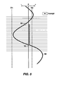
- Figure 5 graphically depicts the use of inflection points to break a trace 50 into peaks and troughs. In this case the number of voxels accepted is determined by the position of the inflection points 52 which bound a seismic trough. In other cases the number of acceptable voxels may be determined by the maximum trace length condition or by the threshold T2 if either one is reached before the inflection point(s).
- Figures 4 and 5 explain the criteria for acceptance or rejection of voxels in trace segments, but they do not cover the method for growing a body laterally from trace to trace.
- This trace to trace jumping or "bleeding" is the source of many problems for conventional seed detection as witnessed by the detection of the one large body in Figures 2B and 3A .
- the present invention takes advantage of constraints provided by the reflections (or local maxima or minima in data other than seismic amplitude) to prevent runaway bleeding of the seed detection. Lateral propagation of a body from one trace to an adjacent trace is only allowed at the peak or trough position. At the beginning of the run the user selects the maximum allowable vertical offset between adjacent peaks or troughs (hereinafter referred to as "Jump_Max" ).
- the Jump_Max limit is spatially variable and derived from calculations of regional stratigraphic dip.
- Figure 6 illustrates how the seismic object is allowed to grow laterally when the trough's vertical offset between traces is less than or equal the Jump_Max setting. Lateral body growth in a given direction terminates when the vertical offset between traces exceeds Jump_Max.
- Figure 6 shows seven adjacent traces 60 through 66. Troughs 60a through 66a are marked.
- the maximum allowable vertical offset (Jump_Max) is set to one. Using this criterion, the seismic object is allowed to grow from trace 60 laterally to trace 63. The seismic object is not permitted to grow to trace 64 because the vertical offset between troughs 63a and 64a exceeds the maximum allowable vertical offset.
- Minimization of body growth across stratigraphic and structural boundaries is a key benefit of the present invention.
- geologically unreasonable bodies can result where a body overlies itself in a spiral pattern, as illustrated by body 70 in Figure 7A .
- the present invention also limits vertical growth by use of an x-y map ( Figure 7B ). Bodies are not permitted to overlie themselves (i.e., a single seismic object may not include more than one discrete segment of any single seismic data trace), and vertically overlapping areas (e.g., area 70a in Figure 7B ) are split into separate bodies (Area 70b in Fig. 7B is distinct from area 70a ) .
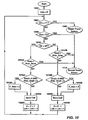
- FIGS 8 to 10 are flowcharts illustrating the primary steps of one computer program for practicing the present invention, and Tables 1 to 3 describe, respectively, the major functions, input controls, and variables used in the program. It will be understood that other computer programs for practicing the present invention could be developed by persons skilled in the art without departing from the true scope of the present invention. It will be understood that the specification of values for the input controls will depend such factors as frequency content of the data, the type of bodies expected or desired to extract, or other, and that iteration will be required by a person skilled in the art when analyzing a typical data set.
- Figure 8 shows the computer program's main loop 800. Since every cell in the seismic data volume is a potential seed point, the main loop preferably is applied to every (x,y,z) cell in the data volume.
- an initial x,y,z cell is selected. Preferably, this initial cell is the 0,0,0 cell; however, any other cell in the data volume may be used as the starting point, if desired.
- the x-y map for the seismic data volume is cleared. The map function is used to track the x-y position of each voxel analyzed and to ensure that no body overlies itself.
- the body size is set to zero. The body size function is used to keep track of the size of growing bodies.
- subroutine Grow (described in detail below in connection with Figure 9 ) is called to attempt to grow a body from the selected x,y,z seed point.
- the size i.e., number of included voxels
- the body is saved at step 812. If not, the body is discarded.
- the program then proceeds to step 814 which checks whether all x,y,z cells in the seismic data volume have been analyzed. If so, the program ends. If not, the program proceeds to step 816 where a new x,y,z cell is picked and steps 804 through 814 are repeated.
- Figure 9 illustrates the program execution flow for the subroutine Grow. This function takes an initial x,y,z point and attempts to grow a body in all directions. Multi-directional growing is accomplished by recursion. Recursion involves having the function repeatedly call itself until all avenues of expansion are blocked by the voxel acceptance criteria.
- Figure 9 illustrates the case where the user has selected troughs for detection.
- the user can also select positive events (peaks in amplitude data) for detection.
- Grow begins with step 902 where the subroutine checks if the cell has been previously visited. The program flow diverts back to the main loop (step 930 ) if the cell has already been checked. If it is a new cell, it is marked as visited in step 904 and the subroutine flow proceeds.
- step 906 a map held in memory is checked to see if the x-y position has already been added to the body in an earlier pass through Grow. If the Check_Map step yields a positive answer then the cell is rejected (detected bodies are not permitted to overlie themselves). Otherwise the map is logged as visited in step 908 and flow continues to step 910 where the voxel is analyzed to see if its attribute value lies outside of the user specified thresholds.
- ChckVrt (discussed below in connection with Figure 10 ), to find the limits of the peak or trough in the specified trace. ChckVrt is actually called twice, once with a search direction value of -1 (search upward) and once with offset equal to + 1 (search downward). If ChckVrt returns a valid trace, the flow continues to step 916 where the program checks the vertical change of the maximum (for peaks) or minimum (troughs) valued voxel from the previous trace. If the vertical offset is within the user specified allowable range (Jump_Max) Grow execution continues.
- Step 918 verifies that the trace has at least the minimum number of valid voxels for inclusion in the body. If the trace has a greater number of valid voxels than that specified by the user, the excess voxels are trimmed from the trace in step 922, which removes extra voxels symmetrically from the top and base of the trace. Preferably, in practice the user would set the maximum allowable trace length based on the wavelength of one-half cycle (peak or trough) of the input seismic survey.
- Step 924 adds the accepted voxels to the total of the growing body that is subsequently saved to a data structure in memory in step 926.
- Step 928 recursively calls subroutine Grow in an effort to expand the body in four directions within the plane containing the current voxel. Program flow returns to the main loop in step 930.
- Step 912 Grow calls another function, ChckVrt (see Figure 10 ), that analyzes the given trace segment vertically to search for inflection points and local minima and maxima.
- ChckVrt is configured to detect troughs. Persons skilled in the art could easily modify this subroutine to detect peaks. In fact, the present inventive method can detect either peaks or trough- based on user input controls.
- ChckVrt determines the number of voxels in a given trace that will be assigned to the body.
- ChckVrt begins with step 1002 where the new trace's length value is initialized. Steps 1004 and 1008 verify that the voxel lies within the desired attribute range.
- step 1004 If the voxel fails the minimum attribute test in step 1004 then the trace is rejected in step 1006 and program flow returns to subroutine Grow. If the voxel within the trace segment is greater than the minimum T2 threshold, the search stops and the voxels accepted up until that point are returned as valid (steps 1008 and 1014).
- step 1010 the program flow is directed down one of two paths depending on the search direction.
- the subsequent steps (1012A - 1022A) are followed when the search direction is upward whereas steps (1012B - 1022B) are used when searching downward.
- the search direction is specified by the parameter Dir on entry to the subroutine. The following description applies to the upward directed search, but it also applies to the downward path with the proviso that the inequality signs in 1012B and 1016B are reversed from 1012A and 1016A to account for the opposite search direction.
- ChckVrt compares the vertical attribute gradient at the current position (current voxel's values minus previous voxel's value) to the gradient calculated in the previous pass through subroutine ChkVrt (step 1012A). If the current gradient is less than the previous gradient the subroutine has detected an inflection point (a transition from trough to peak in this case). Inflection point detection causes the subroutine to accept the trace and return to subroutine Grow in step 1014. If no inflection point is detected, then program flow continues to step 1016A where the voxel is checked to see if it is a local extreme (minimum for troughs or maximum for peaks).
- ChckVrt saves the voxel to the growing body and then moves to step 1022A to increment the vertical position of the counter before running through steps 1004 - 1022A again. ChckVrt execution is complete when the trace segment has been searched up and down and the limits of the event (inflection points of the peak or trough) have been found and/or one or more voxels have been rejected based on threshold constraints.
- the present invention may be used to determine the size of the geobody surrounding a specified seed point.
- the user selects a seed point of interest within a 3D cube.
- the Grow subroutine is then used to attempt to grow a geobody from the specified seed point based on specified stratigraphic criteria, as described above.
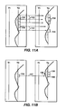
- the present invention includes three additional methods for controlling trace-to-trace (lateral) geobody growth. The first of these is illustrated in Figures 11A and B .
- lateral growth in conventional seed detection, lateral growth (as shown by arrows 112) may take place from any previously selected set of voxels 110 to any laterally adjacent set of voxels 114 that meets the acceptance criteria. This approach may result in bifurcation of the geobody as voxels from more than one event are accepted (voxel 115 in Figure 11A ).
- lateral growth (as shown by arrow 117) only takes place from the local maximum or minimum valued voxel 116 to the next local maximum or minimum valued voxel 118.
- the use of this technique allows lateral growth to be controlled by checking the amount of vertical offset of the peak or trough event (see Figure 6 ).
- the vertical offset from one minimum valued voxel to the next minimum valued equals one voxel (from voxel 120 to voxel 118 in Figure 11B as shown by arrow 119).
- the second method to control geobody growth allows the user to target events in which the local minimum or maximum may not occur at the midway point in two way time (or depth) between inflection points 123.
- Figure 12 presents a case where the user has targeted a "top weighted event" 127.
- a "top weighted event” occurs when the local minimum or maximum occurs in the upper half of an event bounded by two inflection points 123.
- the present invention allows lateral growth, (as shown by arrow 121 ) to occur as long as the user selected event asymmetry criteria are met. When the event does not meet these criteria, growth in that direction is terminated as shown in Figure 12 when the wavelet becomes symmetrical at 129.
- a user may select a top, symmetrical, or bottom weighted event that may be correlated to a subsurface parameter of interest (i.e. porosity).
- the correlation of seismic reflection shape to a parameter of interest may be obtained from subsurface well control. Therefore, the symmetry of a seismic wavelet can be used as an indicator of the spatial distribution of a parameter of interest.
- a parameter of interest may include but is not limited to the net-to-gross reservoir, porosity, fluid type and saturation, lithology, facies, and pore pressure. If the shape of the wavelet is correlated to a parameter of interest, the user may estimate the spatial distribution of parameter of interest throughout a seismic survey by extrapolation of the correlated trace shape.
- the third technique employed by the present invention to control lateral body growth employs a trace-to-trace statistical correlation as an acceptance or rejection criteria.
- This technique is based on a previously patented method for imaging discontinuities in seismic data ( U.S. Patent No. 6,516,274 ).
- the user selects a correlation window (or time window) 130.
- the correlation window need not be in the same length as the thickness of the growing geobody.
- Data from the correlation window is used to select adjacent sets of voxels for correlation as shown in Figure 13A .
- the attribute values of the selected voxels from the source trace 131 and the target trace 132 are cross correlated and a correlation coefficient is calculated (133 in Figure 13B ).
- the correlation value is statistically compares to the cutoff (selected by the user).
- the traces are deemed to be similar enough (meets the user cutoff) the body is allowed to grow to the next trace.
- Step 137 is reached if the traces are deemed not to be similar enough (correlation coefficient is less than the cutoff) and the body is not allowed to grow to the next trace.
- Main Loop Clear_Map() Check X-Y Map Checks the x-y map each time a new voxel is about to be added to a body to make sure that no body can vertically overlie itself.
- Grow Check_Map() Grow Body Primary region (body) growing routine
- Main Loop Grow(x,y,z) Check Trace Vertically Checks if the trace is acceptable when investigated starting at Z and going in the direction dir.
- Grow ChckVrt(Z, dir) Save Trace Stores a vertical stack of voxels within a trace in a growing body. These voxels are part of the current body and they will be saved to output in Save Body() routine.
- Grow Save_Trace() Save Body Saves voxels, which belong to recently detected body.
- the vertical position (z) of the peak or trough in the trace being analyzed Grow, ChckVrt Z_max Z Position of Maximum (Peak) or Minimum (Trough) of Previous Trace
- Grow, ChckVrt Z_max_prev Vertical Attribute Gradient The change from voxel to voxel measured vertically on a given trace.
- ChckVrt Grad Previous Vertical Attribute Gradient The change from voxel to voxel measured vertically in the trace analyzed in the previous vertical growth step. Used to search for inflection points in an attribute along a given trace.
- ChckVrt Grad_Prev Trace Search Direction Dir is set to 1 to check trace characteristics downward and -1 for checking upwards.
Landscapes
- Engineering & Computer Science (AREA)
- Life Sciences & Earth Sciences (AREA)
- Environmental & Geological Engineering (AREA)
- Remote Sensing (AREA)
- Physics & Mathematics (AREA)
- Emergency Management (AREA)
- Business, Economics & Management (AREA)
- Acoustics & Sound (AREA)
- Geology (AREA)
- General Life Sciences & Earth Sciences (AREA)
- General Physics & Mathematics (AREA)
- Geophysics (AREA)
- Geophysics And Detection Of Objects (AREA)
Claims (17)
- Verfahren zur Bestimmung der Größe und Form eines seismischen Objekts in einem seismischen 3D-Datenvolumen, wobei das Verfahren die folgenden Schritte aufweist:(a) Bestimmen des Wertes eines vorausgewählten seismischen Attributs an einer Vielzahl von Datenpunkten,(b) Auswählen eines ersten Satzes von Kriterien zur Klassifizierung seismischer Daten auf Basis der Attributwerte als akzeptabel oder nicht akzeptabel zur Einbeziehung in ein seismisches Objekt,
DADURCH GEKENNZEICHNET, DASS- das seismische 3D-Datenvolumen eine Vielzahl von vertikalen seismischen Datenspuren aufweist,- der Wert des vorausgewählten seismischen Attributs an einer Vielzahl von Datenpunkten entlang jeder seismischen Datenspur bestimmt wird und- der erste Satz von Kriterien zur Unterteilung jeder seismischen Datenspur auf Basis der Attributwerte in Spursegmente ausgewählt wird, die entweder akzeptabel oder nicht akzeptabel zur Einbeziehung in ein seismisches Objekt sind,UND DADURCH, DASS das Verfahren ferner die Schritte aufweist,(c) einen zweiten Satz von Kriterien zum Ermöglichen oder Verhindern einer lateralen Ausbreitung des seismischen Objekts von einer seismischen Datenspur zu einer benachbarten seismischen Datenspur auszuwählen,(d) einen Saatpunkt auszuwählen, der in das seismische Objekt fällt, und das seismische Objekt um den Saatpunkt herum auf Basis des ersten und des zweiten Satzes von Kriterien wachsen zu lassen und(e) die Größe und Form des seismischen Objekts auszugeben. - Verfahren nach Anspruch 1, bei dem die Schritte (d) und (e) des Verfahrens die Schritte aufweist,(i) einen anfänglichen Datenpunkt in dem seismischen 3D-Datenvolumen als ein Saatpunkt auszuwählen und zu versuchen, ein seismisches Objekt um den Saatpunkt herum auf Basis des ersten und des zweiten Satzes von Kriterien wachsen zu lassen,(ii) den Schritts (i) für jeden anderen Datenpunkt in dem seismischen 3D-Datenvolumen zu wiederholen und(iii) seismische Objekte auzugeben, die vorausgewählte Kriterien für minimale und maximale Größe erfüllen.
- Verfahren nach Anspruch 1 oder Anspruch 2, bei dem der erste Satz von Kriterien Schwellenkriterien für den Wert des vorausgewählten seismischen Attributs und Spursegmentlängenanforderungen enthält.
- Verfahren nach Anspruch 3, bei dem die Schwellenkriterien eine minimale und maximale Schwelle für den Wert des vorausgewählten seismischen Attributs enthalten.
- Verfahren nach Anspruch 3, bei dem die Spursegmentlängenanforderungen eine minimale und maximale Länge für akzeptable Spursegmente enthalten.
- Verfahren nach Anspruch 5, bei dem Spursegmente, die die maximale Längenanforderung überschreiten, symmetrisch auf die maximale Länge beschnitten und dann akzeptiert werden.
- Verfahren nach Anspruch 1 oder Anspruch 2, bei dem eine laterale Ausbreitung des seismischen Objekts von der einen seismischen Datenspur zu der benachbarten seismischen Datenspur nur an Gipfelpunkten (lokalen Maxima) oder Tiefpunkten (lokalen Minima) von akzeptablen Datenspursegmenten zugelassen wird und bei dem der zweite Satz von Kriterien einen maximalen vertikalen Versatz zwischen entsprechenden akzeptablen Gipfelpunkten oder Tiefpunkten an benachbarten seismischen Datenspuren enthält.
- Verfahren nach Anspruch 7, bei dem der maximale vertikale Versatz räumlich variabel ist und von einer Berechnung eines regionalen stratigrafischen Fallens abgeleitet wird.
- Verfahren nach Anspruch 1 oder Anspruch 2, bei dem das vorausgewählte seismische Attribut eine seismische Amplitude ist.
- Verfahren nach Anspruch 1 oder Anspruch 2, bei dem das vorausgewählte seismische Attribut eine akustische Impedanz ist.
- Verfahren nach Anspruch 1 oder Anspruch 2, bei dem das vorausgewählte seismische Attribut eine Diskontinuität ist.
- Verfahren nach Anspruch 1 oder Anspruch 2, bei dem das Verfahren ferner den Schritt aufweist, zu verhindern, dass jegliches seismische Objekt mehr als ein diskretes Segment von irgendeiner einzelnen seismischen Datenspur enthält.
- Verfahren nach Anspruch 1 oder Anspruch 2, bei dem die laterale Ausbreitung gesteuert wird, indem das Ausmaß des vertikalen Versatzes des lokalen Minimums oder Maximum geprüft wird.
- Verfahren nach Anspruch 1 oder Anspruch 2, bei dem das laterale Wachstum durch die Form eines Wavelets gesteuert wird.
- Verfahren nach Anspruch 14, das ferner aufweist, die Form des Wavelets mit einem interessierenden Parameter zu korrelieren und die Korrelation der Form des interessierenden Parameters zu verwenden, um den interessierenden Parameter überall in einer seismischen Messung zu schätzen.
- Verfahren nach Anspruch 14, bei dem der interessierende Parameter aus der Gruppe ausgewählt ist, die Netto/Brutto, Porosität, Fluidtyp, Sättigung, Lithologie und Fazies und jegliche Kombinationen davon umfasst.
- Verfahren nach Anspruch 1 oder Anspruch 2, bei dem das laterale Wachstum durch eine statistische Korrelation von Spur zu Spur gesteuert wird.
Applications Claiming Priority (3)
| Application Number | Priority Date | Filing Date | Title |
|---|---|---|---|
| US41381402P | 2002-09-26 | 2002-09-26 | |
| US413814P | 2002-09-26 | ||
| PCT/US2003/027263 WO2004029715A1 (en) | 2002-09-26 | 2003-09-03 | Method for performing stratigraphically-based seed detection in a3-d seismic data volume |
Publications (3)
| Publication Number | Publication Date |
|---|---|
| EP1550001A1 EP1550001A1 (de) | 2005-07-06 |
| EP1550001A4 EP1550001A4 (de) | 2011-07-13 |
| EP1550001B1 true EP1550001B1 (de) | 2013-03-27 |
Family
ID=32043294
Family Applications (1)
| Application Number | Title | Priority Date | Filing Date |
|---|---|---|---|
| EP03798708A Expired - Lifetime EP1550001B1 (de) | 2002-09-26 | 2003-09-03 | Verfahren zur durchführung von stratigraphisch basierter anfangswertdetektion in einem seismischen 3d-datenvolumen |
Country Status (8)
| Country | Link |
|---|---|
| US (1) | US7024021B2 (de) |
| EP (1) | EP1550001B1 (de) |
| AU (1) | AU2003263015B2 (de) |
| BR (1) | BR0318292A (de) |
| CA (1) | CA2499948C (de) |
| MY (1) | MY134388A (de) |
| NO (1) | NO336492B1 (de) |
| WO (1) | WO2004029715A1 (de) |
Families Citing this family (68)
| Publication number | Priority date | Publication date | Assignee | Title |
|---|---|---|---|---|
| US7433785B2 (en) | 2003-03-13 | 2008-10-07 | Exxon Mobil Upstream Research Company | Method for predicting grain size distribution from reservoir thickness |
| CA2520135A1 (en) * | 2003-03-31 | 2004-11-04 | Exxonmobil Upstream Research Company | Method to determine properties of a sedimentary body from thickness and grain size distribution at a point within the body |
| US7266041B1 (en) * | 2005-06-21 | 2007-09-04 | Michael John Padgett | Multi-attribute background relative scanning of 3D geophysical datasets for locally anomaluous data points |
| US7310435B2 (en) * | 2003-11-25 | 2007-12-18 | General Electric Company | Method and apparatus for extracting multi-dimensional structures using dynamic constraints |
| US20050171700A1 (en) * | 2004-01-30 | 2005-08-04 | Chroma Energy, Inc. | Device and system for calculating 3D seismic classification features and process for geoprospecting material seams |
| WO2005104003A1 (en) * | 2004-03-31 | 2005-11-03 | Exxonmobil Upstream Research Company | Method for constructing a geologic model of a subsurface reservoir |
| AU2005285360B2 (en) * | 2004-09-10 | 2011-02-03 | Exxonmobil Upstream Research Company | A method for constructing geologic models of subsurface sedimentary volumes |
| US8776895B2 (en) | 2006-03-02 | 2014-07-15 | Exxonmobil Upstream Research Company | Method for quantifying reservoir connectivity using fluid travel times |
| EP2372398A3 (de) * | 2006-06-21 | 2012-04-11 | Terraspark Geosciences, LLC | Extraktion von Ablagerungssystemen |
| WO2008086196A1 (en) * | 2007-01-05 | 2008-07-17 | Landmark Graphics Corporation, A Halliburton Company | Systems and methods for selectively imaging objects in a display of multiple three-dimensional data-objects |
| US8346695B2 (en) * | 2007-03-29 | 2013-01-01 | Schlumberger Technology Corporation | System and method for multiple volume segmentation |
| EP2031423B1 (de) * | 2007-08-31 | 2013-05-15 | Services Pétroliers Schlumberger | Identifizierung geologischer Eigenschaften auf einem Bild einer ein Bohrloch umgebenden unterirdischen Formation |
| CA2705197C (en) * | 2007-11-14 | 2015-11-10 | Terraspark Geosciences, L.P. | Seismic data processing |
| CA2705277C (en) * | 2007-12-18 | 2017-01-17 | Exxonmobil Upstream Research Company | Determining connectivity architecture in 2-d and 3-d heterogeneous data |
| EP2232406A4 (de) * | 2007-12-21 | 2017-10-18 | Exxonmobil Upstream Research Company | Verfahren und vorrichtung zum analysieren dreidimensionaler daten |
| WO2009114211A1 (en) | 2008-03-10 | 2009-09-17 | Exxonmobil Upstream Research Company | Method for determing distinct alternative paths between two object sets in 2-d and 3-d heterogeneous data |
| US20110006690A1 (en) * | 2008-03-18 | 2011-01-13 | Shenzhen Tcl New Technology Ltd. | Apparatus and method for managing the power of an electronic device |
| US8803878B2 (en) * | 2008-03-28 | 2014-08-12 | Schlumberger Technology Corporation | Visualizing region growing in three dimensional voxel volumes |
| CA2721008A1 (en) * | 2008-04-11 | 2009-10-15 | Terraspark Geosciences, Llc | Visulation of geologic features using data representations thereof |
| EP2113796A1 (de) | 2008-04-30 | 2009-11-04 | ExxonMobil Upstream Research Company | Verfahren und Vorrichtung zur Analyse dreidimensionaler Daten |
| US9733388B2 (en) | 2008-05-05 | 2017-08-15 | Exxonmobil Upstream Research Company | Systems and methods for connectivity analysis using functional objects |
| US8360144B2 (en) * | 2008-05-09 | 2013-01-29 | Exxonmobil Upstream Research Company | Method for geophysical and stratigraphic interpretation using waveform anomalies |
| US8213261B2 (en) * | 2008-05-22 | 2012-07-03 | Exxonmobil Upstream Research Company | Method for geophysical and geological interpretation of seismic volumes in the domains of depth, time, and age |
| MY164574A (en) * | 2008-05-22 | 2018-01-15 | Exxonmobil Upstream Res Co | Seismic horizon skeletonization |
| CN102047294B (zh) * | 2008-06-06 | 2013-10-30 | 兰德马克绘图国际公司,哈里伯顿公司 | 对表示网格体的几何不规则网格数据的三维体成像的系统及方法 |
| FR2932280B1 (fr) * | 2008-06-06 | 2010-06-18 | Inst Francais Du Petrole | Procede pour construire un modele structural au moyen de techniques de vision cognitive. |
| FR2939520B1 (fr) * | 2008-12-10 | 2011-05-20 | Elite Image Software | Procede de modelisation geologique de donnees sismiques par correlation de traces |
| US20100214870A1 (en) * | 2009-02-23 | 2010-08-26 | Randolph Pepper | Method and apparatus for dynamic extraction of extrema-based geometric primitives in 3d voxel volumes |
| US8600708B1 (en) | 2009-06-01 | 2013-12-03 | Paradigm Sciences Ltd. | Systems and processes for building multiple equiprobable coherent geometrical models of the subsurface |
| US9418182B2 (en) | 2009-06-01 | 2016-08-16 | Paradigm Sciences Ltd. | Systems and methods for building axes, co-axes and paleo-geographic coordinates related to a stratified geological volume |
| US9536022B1 (en) | 2009-06-01 | 2017-01-03 | Paradigm Sciences Ltd. | Systems and methods for modeling faults in the subsurface |
| US8711140B1 (en) | 2009-06-01 | 2014-04-29 | Paradigm Sciences Ltd. | Systems and methods for building axes, co-axes and paleo-geographic coordinates related to a stratified geological volume |
| US8774468B2 (en) * | 2009-09-08 | 2014-07-08 | Schlumberger Technology Corporation | Dynamic shape approximation |
| US8743115B1 (en) | 2009-10-23 | 2014-06-03 | Paradigm Sciences Ltd. | Systems and methods for coordinated editing of seismic data in dual model |
| US9330494B2 (en) * | 2009-10-26 | 2016-05-03 | Pictometry International Corp. | Method for the automatic material classification and texture simulation for 3D models |
| WO2011056347A1 (en) * | 2009-11-05 | 2011-05-12 | Exxonmobil Upstream Research Company | Method for creating a hierarchically layered earth model |
| US8355872B2 (en) * | 2009-11-19 | 2013-01-15 | Chevron U.S.A. Inc. | System and method for reservoir analysis background |
| US8498177B2 (en) * | 2010-08-20 | 2013-07-30 | Schlumberger Technology Corporation | Determining a position of a geological layer relative to a wavelet response in seismic data |
| WO2012141799A2 (en) | 2011-02-25 | 2012-10-18 | University Of Florida Research Foundation, Inc. | Detection of sinkholes or anomalies |
| US9128204B2 (en) | 2011-04-15 | 2015-09-08 | Exxonmobil Upstream Research Company | Shape-based metrics in reservoir characterization |
| USD685391S1 (en) | 2011-06-27 | 2013-07-02 | Specialty Minerals (Michigan) Inc. | Graphical user interface for a display screen or a portion thereof for evaluating refractory data |
| US8843353B2 (en) * | 2011-08-25 | 2014-09-23 | Chevron U.S.A. Inc. | Hybrid deterministic-geostatistical earth model |
| EP2776864A4 (de) * | 2011-11-11 | 2016-03-09 | Exxonmobil Upstream Res Co | Verfahren zur erzeugung und kombination mehrerer horizonte zur bestimmung eines seismischen horizonts und seiner unsicherheit |
| US10114134B2 (en) | 2012-03-02 | 2018-10-30 | Emerson Paradigm Holding Llc | Systems and methods for generating a geological model honoring horizons and faults |
| US9329690B2 (en) * | 2012-03-09 | 2016-05-03 | Schlumberger Technology Corporation | Multitouch control of petrotechnical software |
| US9759826B2 (en) | 2012-04-03 | 2017-09-12 | Paradigm Sciences Ltd. | System and method for generating an implicit model of geological horizons |
| GB2503506B (en) | 2012-06-29 | 2014-12-03 | Foster Findlay Ass Ltd | Adaptive horizon tracking |
| RU2516590C1 (ru) * | 2012-12-11 | 2014-05-20 | Федеральное государственное учреждение науки Институт нефтегазовой геологии и геофизики им. А.А. Трофимука Сибирского отделения Российской академии наук (ИНГГ СО РАН) | Способ построения непрерывных сейсмостратиграфических моделей разрезов/кубов |
| RU2015123454A (ru) | 2012-12-13 | 2017-01-16 | Лэндмарк Графикс Корпорейшн | Система, способ и компьютерный программный продукт для оценки и классификации геологических тел с использованием эйлеровой характеристики |
| EP3418778B1 (de) | 2013-03-15 | 2020-07-15 | Emerson Paradigm Holding LLC | Systeme und verfahren zum aufbauen sedimentärer attribute |
| CA153915S (en) * | 2013-05-22 | 2014-10-28 | Bergen Technology Ct As | Computer display screen from a well sonde |
| WO2014197160A1 (en) | 2013-06-06 | 2014-12-11 | Exxonmobil Upstream Research Comapny | Method for decomposing complex objects into simpler components |
| SG11201601163UA (en) * | 2013-10-08 | 2016-03-30 | Landmark Graphics Corp | Automated horizon auto-picking on multiple volumes |
| EP2869096B1 (de) | 2013-10-29 | 2019-12-04 | Emerson Paradigm Holding LLC | Systeme und verfahren zur multiskalaren vermaschung von geologischer zeitmodellierung |
| WO2015065602A1 (en) * | 2013-10-31 | 2015-05-07 | Exxonmobil Upstream Research Company | Automatic tracking of faults by slope decomposition |
| US10422923B2 (en) | 2014-03-28 | 2019-09-24 | Emerson Paradigm Holding Llc | Systems and methods for modeling fracture networks in reservoir volumes from microseismic events |
| US9690002B2 (en) | 2015-06-18 | 2017-06-27 | Paradigm Sciences Ltd. | Device, system and method for geological-time refinement |
| CN105089658B (zh) * | 2015-07-01 | 2018-04-06 | 中国石油天然气股份有限公司 | 基于不确定度的地层对比方法及装置 |
| US10036820B2 (en) | 2016-03-04 | 2018-07-31 | General Electric Company | Expert guided knowledge acquisition system for analyzing seismic data |
| CN106048983B (zh) * | 2016-07-20 | 2018-03-20 | 惠而浦(中国)股份有限公司 | 一种滚筒洗衣机负载量和偏心量的检测方法 |
| US10466388B2 (en) | 2016-09-07 | 2019-11-05 | Emerson Paradigm Holding Llc | System and method for editing geological models by switching between volume-based models and surface-based structural models augmented with stratigraphic fiber bundles |
| GB2565526A (en) * | 2017-06-12 | 2019-02-20 | Foster Findlay Ass Ltd | A method for validating geological model data over corresponding original seismic data |
| US11156744B2 (en) | 2019-01-10 | 2021-10-26 | Emerson Paradigm Holding Llc | Imaging a subsurface geological model at a past intermediate restoration time |
| US10520644B1 (en) | 2019-01-10 | 2019-12-31 | Emerson Paradigm Holding Llc | Imaging a subsurface geological model at a past intermediate restoration time |
| US11542816B2 (en) | 2021-01-28 | 2023-01-03 | Saudi Arabian Oil Company | System and method for hydrocarbon exploration based on imaging tunnel valleys |
| CN115639600B (zh) * | 2021-07-19 | 2026-03-20 | 中国石油化工股份有限公司 | 基于区域生长技术的地震相自动识别方法 |
| CN113687423B (zh) * | 2021-08-04 | 2024-03-01 | 潜能恒信能源技术股份有限公司 | 一种基于界面提取的地震资料解释方法和系统 |
| CN113807305B (zh) * | 2021-09-27 | 2024-08-13 | 宫雪峰 | 基于朴素贝叶斯分类算法的道路破坏性预测自动驾驶方法 |
Family Cites Families (22)
| Publication number | Priority date | Publication date | Assignee | Title |
|---|---|---|---|---|
| US4633401A (en) * | 1984-11-08 | 1986-12-30 | Texas Instruments Incorporated | Method and apparatus for automatically determining pairs of turnings related to the same seismic event in adjacent seismic traces |
| US4751643A (en) | 1986-08-04 | 1988-06-14 | General Electric Company | Method and apparatus for determining connected substructures within a body |
| US5056066A (en) * | 1990-06-25 | 1991-10-08 | Landmark Graphics Corporation | Method for attribute tracking in seismic data |
| US5153858A (en) | 1991-07-09 | 1992-10-06 | Landmark Graphics Corporation | Method for finding horizons in 3D seismic data |
| US5128899A (en) * | 1991-07-16 | 1992-07-07 | Conoco Inc. | Method for sharpening prestack depth migration images by removing residual moveout from common image point gathers before stacking |
| GB9214482D0 (en) * | 1992-07-08 | 1992-08-19 | Armitage Kenneth | Sequence property interpretation & risk analysis link |
| US5501273A (en) * | 1994-10-04 | 1996-03-26 | Amoco Corporation | Method for determining the reservoir properties of a solid carbonaceous subterranean formation |
| US5563949A (en) | 1994-12-12 | 1996-10-08 | Amoco Corporation | Method of seismic signal processing and exploration |
| US5586082A (en) * | 1995-03-02 | 1996-12-17 | The Trustees Of Columbia University In The City Of New York | Method for identifying subsurface fluid migration and drainage pathways in and among oil and gas reservoirs using 3-D and 4-D seismic imaging |
| US5671136A (en) * | 1995-12-11 | 1997-09-23 | Willhoit, Jr.; Louis E. | Process for seismic imaging measurement and evaluation of three-dimensional subterranean common-impedance objects |
| US5838634A (en) | 1996-04-04 | 1998-11-17 | Exxon Production Research Company | Method of generating 3-D geologic models incorporating geologic and geophysical constraints |
| US5884229A (en) | 1996-06-10 | 1999-03-16 | Exxon Production Research Company | Method for measuring lateral continuity at a specified subsurface location from seismic data |
| US5894417A (en) * | 1996-09-19 | 1999-04-13 | Atlantic Richfield Company | Method and system for horizon interpretation of seismic surveys using surface draping |
| US5835882A (en) * | 1997-01-31 | 1998-11-10 | Phillips Petroleum Company | Method for determining barriers to reservoir flow |
| US5966672A (en) * | 1997-07-28 | 1999-10-12 | Knupp; Daniel F. | Visualization technology method |
| US6018498A (en) * | 1998-09-02 | 2000-01-25 | Phillips Petroleum Company | Automated seismic fault detection and picking |
| DE19904347C2 (de) * | 1999-02-03 | 2002-08-14 | Henning Trappe | Verfahren zur seismischen Datenverarbeitung |
| CA2414631C (en) * | 2000-06-30 | 2008-09-30 | Exxonmobil Upstream Research Company | Method for imaging discontinuities in seismic data using dip-steering |
| EP1358510B1 (de) * | 2001-01-31 | 2006-07-26 | Landmark Graphics Corporation | Verfahren zur analyse und abbildung einer angereicherten dreidimensionalen volumendatenmenge unter verwendung von mind. zwei attributen und computer programm dafür |
| US6690820B2 (en) * | 2001-01-31 | 2004-02-10 | Magic Earth, Inc. | System and method for analyzing and imaging and enhanced three-dimensional volume data set using one or more attributes |
| US6823266B2 (en) * | 2001-06-20 | 2004-11-23 | Exxonmobil Upstream Research Company | Method for performing object-based connectivity analysis in 3-D seismic data volumes |
| US6674689B2 (en) * | 2002-04-12 | 2004-01-06 | Exxonmobil Upstream Research Company | Method for morphologic analysis of seismic objects |
-
2003
- 2003-09-03 BR BRPI0318292-4A patent/BR0318292A/pt not_active IP Right Cessation
- 2003-09-03 US US10/654,138 patent/US7024021B2/en not_active Expired - Lifetime
- 2003-09-03 AU AU2003263015A patent/AU2003263015B2/en not_active Expired
- 2003-09-03 EP EP03798708A patent/EP1550001B1/de not_active Expired - Lifetime
- 2003-09-03 CA CA002499948A patent/CA2499948C/en not_active Expired - Lifetime
- 2003-09-03 WO PCT/US2003/027263 patent/WO2004029715A1/en not_active Ceased
- 2003-09-12 MY MYPI20033485A patent/MY134388A/en unknown
-
2005
- 2005-03-23 NO NO20051569A patent/NO336492B1/no not_active IP Right Cessation
Also Published As
| Publication number | Publication date |
|---|---|
| WO2004029715A1 (en) | 2004-04-08 |
| BR0318292A (pt) | 2006-07-11 |
| AU2003263015B2 (en) | 2009-01-22 |
| US7024021B2 (en) | 2006-04-04 |
| NO336492B1 (no) | 2015-09-07 |
| NO20051569D0 (no) | 2005-03-23 |
| CA2499948C (en) | 2009-10-27 |
| MY134388A (en) | 2007-12-31 |
| EP1550001A1 (de) | 2005-07-06 |
| US20040062145A1 (en) | 2004-04-01 |
| EP1550001A4 (de) | 2011-07-13 |
| NO20051569L (no) | 2005-06-27 |
| CA2499948A1 (en) | 2004-04-08 |
| AU2003263015A1 (en) | 2004-04-19 |
Similar Documents
| Publication | Publication Date | Title |
|---|---|---|
| EP1550001B1 (de) | Verfahren zur durchführung von stratigraphisch basierter anfangswertdetektion in einem seismischen 3d-datenvolumen | |
| US6823266B2 (en) | Method for performing object-based connectivity analysis in 3-D seismic data volumes | |
| CA2481907C (en) | Method for morphologic analysis of seismic objects | |
| US6295504B1 (en) | Multi-resolution graph-based clustering | |
| CN102066980B (zh) | 地震层位骨架化 | |
| US6618678B1 (en) | Method of joint analysis and interpretation of the subsurface from multiple seismic derived layer property data sets | |
| US8213261B2 (en) | Method for geophysical and geological interpretation of seismic volumes in the domains of depth, time, and age | |
| CA2705340C (en) | Method and apparatus for analyzing three-dimensional data | |
| EP2113796A1 (de) | Verfahren und Vorrichtung zur Analyse dreidimensionaler Daten | |
| AU2002312550B2 (en) | Method for performing object-based connectivity analysis in 3-D seismic data volumes | |
| AU2002312550A1 (en) | Method for performing object-based connectivity analysis in 3-D seismic data volumes | |
| Whitehead et al. | Identifying stratigraphic units by seismic patterns | |
| Singh et al. | Facies classification based on seismic waveform–a case study from Mumbai High North | |
| CN117192612A (zh) | 一种高精度的浊积砂体地震识别方法 | |
| Vossler | Automatic delineation of lateral facies changes in clastic environments |
Legal Events
| Date | Code | Title | Description |
|---|---|---|---|
| PUAI | Public reference made under article 153(3) epc to a published international application that has entered the european phase |
Free format text: ORIGINAL CODE: 0009012 |
|
| 17P | Request for examination filed |
Effective date: 20050426 |
|
| AK | Designated contracting states |
Kind code of ref document: A1 Designated state(s): AT BE BG CH CY CZ DE DK EE ES FI FR GB GR HU IE IT LI LU MC NL PT RO SE SI SK TR |
|
| AX | Request for extension of the european patent |
Extension state: AL LT LV MK |
|
| DAX | Request for extension of the european patent (deleted) | ||
| RBV | Designated contracting states (corrected) |
Designated state(s): FR GB NL |
|
| REG | Reference to a national code |
Ref country code: DE Ref legal event code: 8566 |
|
| A4 | Supplementary search report drawn up and despatched |
Effective date: 20110615 |
|
| 17Q | First examination report despatched |
Effective date: 20111018 |
|
| GRAP | Despatch of communication of intention to grant a patent |
Free format text: ORIGINAL CODE: EPIDOSNIGR1 |
|
| GRAS | Grant fee paid |
Free format text: ORIGINAL CODE: EPIDOSNIGR3 |
|
| GRAA | (expected) grant |
Free format text: ORIGINAL CODE: 0009210 |
|
| AK | Designated contracting states |
Kind code of ref document: B1 Designated state(s): FR GB NL |
|
| REG | Reference to a national code |
Ref country code: GB Ref legal event code: FG4D |
|
| REG | Reference to a national code |
Ref country code: NL Ref legal event code: T3 |
|
| PLBE | No opposition filed within time limit |
Free format text: ORIGINAL CODE: 0009261 |
|
| STAA | Information on the status of an ep patent application or granted ep patent |
Free format text: STATUS: NO OPPOSITION FILED WITHIN TIME LIMIT |
|
| 26N | No opposition filed |
Effective date: 20140103 |
|
| REG | Reference to a national code |
Ref country code: FR Ref legal event code: PLFP Year of fee payment: 14 |
|
| REG | Reference to a national code |
Ref country code: FR Ref legal event code: PLFP Year of fee payment: 15 |
|
| REG | Reference to a national code |
Ref country code: FR Ref legal event code: PLFP Year of fee payment: 16 |
|
| PGFP | Annual fee paid to national office [announced via postgrant information from national office to epo] |
Ref country code: NL Payment date: 20220926 Year of fee payment: 20 Ref country code: GB Payment date: 20220920 Year of fee payment: 20 |
|
| PGFP | Annual fee paid to national office [announced via postgrant information from national office to epo] |
Ref country code: FR Payment date: 20220926 Year of fee payment: 20 |
|
| P01 | Opt-out of the competence of the unified patent court (upc) registered |
Effective date: 20230518 |
|
| REG | Reference to a national code |
Ref country code: NL Ref legal event code: MK Effective date: 20230902 |
|
| REG | Reference to a national code |
Ref country code: GB Ref legal event code: PE20 Expiry date: 20230902 |
|
| PG25 | Lapsed in a contracting state [announced via postgrant information from national office to epo] |
Ref country code: GB Free format text: LAPSE BECAUSE OF EXPIRATION OF PROTECTION Effective date: 20230902 |