EP1549104B1 - Speaker device - Google Patents
Speaker device Download PDFInfo
- Publication number
- EP1549104B1 EP1549104B1 EP04772830A EP04772830A EP1549104B1 EP 1549104 B1 EP1549104 B1 EP 1549104B1 EP 04772830 A EP04772830 A EP 04772830A EP 04772830 A EP04772830 A EP 04772830A EP 1549104 B1 EP1549104 B1 EP 1549104B1
- Authority
- EP
- European Patent Office
- Prior art keywords
- loudspeaker
- loudspeakers
- circuit board
- printed circuit
- loudspeaker apparatus
- Prior art date
- Legal status (The legal status is an assumption and is not a legal conclusion. Google has not performed a legal analysis and makes no representation as to the accuracy of the status listed.)
- Expired - Lifetime
Links
Images



Classifications
-
- H—ELECTRICITY
- H04—ELECTRIC COMMUNICATION TECHNIQUE
- H04R—LOUDSPEAKERS, MICROPHONES, GRAMOPHONE PICK-UPS OR LIKE ACOUSTIC ELECTROMECHANICAL TRANSDUCERS; ELECTRIC HEARING AIDS; PUBLIC ADDRESS SYSTEMS
- H04R9/00—Transducers of moving-coil, moving-strip, or moving-wire type
- H04R9/02—Details
-
- H—ELECTRICITY
- H04—ELECTRIC COMMUNICATION TECHNIQUE
- H04R—LOUDSPEAKERS, MICROPHONES, GRAMOPHONE PICK-UPS OR LIKE ACOUSTIC ELECTROMECHANICAL TRANSDUCERS; ELECTRIC HEARING AIDS; PUBLIC ADDRESS SYSTEMS
- H04R9/00—Transducers of moving-coil, moving-strip, or moving-wire type
- H04R9/06—Loudspeakers
Definitions
- the present invention relates to a loudspeaker apparatus mainly disposed at both sides of a television receiver.
- a television receiver has been required to be large and thin, and also required to be compact. Therefore, a loudspeaker apparatus disposed at both sides of the television receiver is required to be thin and elongated.
- This kind of elongated loudspeaker is shown in Figs. 5A to 5C.
- Fig. 5A is a plan view of the loudspeaker
- Fig. 5B is a sectional view thereof in a major axis direction
- Fig. 5C is a sectional view thereof in a minor axis direction.
- inverted dome shaped diaphragm 1 has a nonaxis-symmetric shape having a major axis and a minor axis in a plane structure viewed from a vibration direction.
- diaphragm 1 bulges in a reverse direction in which sounds are emitted.
- Edge 2 is connected with an outer periphery of diaphragm 1 and held by frame 5.
- Magnetic circuit 10 is installed at a bottom of frame 5, and formed of yoke 8, magnet 7, plate 6 and the like.
- Dust net 9 is disposed at a window of frame 5 and prevents dust from entering into magnetic circuit 10.
- Beltlike (i.e. track shape) voice coil bobbin 3 is formed along an outer periphery of diaphragm 1 in parallel to the vibration direction, and connected with the outer periphery of diaphragm 1.
- Voice coil (not shown) is wound around a position corresponding to magnetic gap 10a of magnetic circuit 10.
- the loudspeakers structured discussed above are disposed at both sides of the television receiver which is not shown here.
- Unexamined Japanese Patent Publication H9-200891 is known as a conventional art related to the present invention.
- WO 97/16913 A describes a loudspeaker fastened to a circuit board via adhesive means and the diaphragm facing towards the board which has holes opposite to the loudspeaker.
- a loudspeaker apparatus of an improved large and thin structure which can be manufactured easily is obtained by the features of claim 1.
- a conventional loudspeaker is long in a major axis direction, so that it is required to produce track shaped voice coil bobbin 3 without meandering, allow for a margin of magnetic gap 10a because of deformation of voice coil bobbin 3, and prevent magnetic circuit 10 and frame 5 from warping. Therefore, manufacturing of the loudspeaker becomes complicate and high cost.
- the present invention is directed to solve the problems discussed above, and aims to provide an elongated and easy-manufacturing loudspeaker apparatus.
- the present invention has the following structure to solve the problems pointed out above.
- the loudspeaker apparatus of the present invention includes an elongated printed circuit board, and a plurality of loudspeakers mounted on the printed circuit board and aligned substantially straightly in much the same direction as a longitudinal direction of the elongated printed circuit board, where each terminal for inputting a signal of the loudspeakers is electrically coupled with a conductive pattern part of the printed circuit board.
- signal inputting parts for inputting a signal from an outside are formed by leading the conductive pattern part to at least both ends of the printed circuit board in the longitudinal direction or neighborhoods thereof.
- the elongated loudspeaker apparatus can be easily provided by arranging a plurality of easy-manufacturing loudspeakers.
- the signal inputting parts for inputting a signal from an outside are formed at ends of the printed circuit board or neighborhoods thereof. Therefore, when the loudspeaker apparatuses are disposed at both sides of a monitor, a main-unit-side circuit of a television receiver, which is generally disposed at a bottom of a cabinet, and the loudspeaker apparatuses disposed at both sides thereof can be coupled with each other under the loudspeaker apparatuses. As a result, assembling devices becomes easy.
- the signal inputting part discussed above is a terminal directly connected with a connector which is coupled with another printed circuit board (e.g. circuit board of a main device) or another printed circuit. Therefore, efficiency of assembling devices further improves.
- the loudspeaker apparatus of the present invention in the loudspeaker apparatus mentioned above, a plurality of loudspeakers are electrically coupled with one another, so that its synthetic impedance is equalized or approximated to an impedance of one loudspeaker. Therefore, even if a main-device-side amplifier is designed based on one loudspeaker, the loudspeaker apparatus of the present invention can be used. As a result, variation from a popular model to a high grade model of an acoustic apparatus of the main device can be provided by changing only the loudspeaker apparatus.
- the loudspeakers of the loudspeaker apparatus discussed above are electrically coupled in series. Therefore, the same effect as that mentioned above can be obtained without increasing a load of a main-device-side amplifier.
- a high cut filter which restrains an input at high frequencies of at least one terminal-section-side loudspeaker of a plurality of loudspeakers disposed at the loudspeaker apparatus, is coupled with the conductive pattern part of the printed circuit board. Therefore, directivity of loudspeakers at a high reproducing frequency can be restrained, which is generated by aligning a plurality of loudspeakers straightly in an arrangement direction.
- the elongated loudspeaker can be easily manufactured and main device circuit board can be easily coupled.
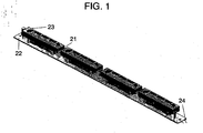
- Fig. 1 is a perspective view showing a loudspeaker apparatus of the present invention.
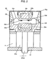
- Fig. 2 is a sectional view of a loudspeaker, which is mounted on a printed circuit board in a minor axis direction and an essential part of the loudspeaker apparatus of the present invention.
- Fig. 3 is a circuit diagram of the loudspeaker apparatus of the present invention.
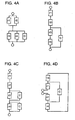
- Figs. 4A-4B each is another example of a circuit diagram of the loudspeaker apparatus of the present invention.
- reference mark 21 denotes the loudspeaker apparatus
- reference mark 22 denotes an elongated printed circuit board having a conductive pattern
- reference marks 23 denote a plurality of loudspeakers. Loudspeakers 23 are aligned substantially straightly on rectangular printed circuit board 22, and coupled electrically and mechanically therewith.
- Reference mark 24 denotes a lead wire for inputting an outer sound signal and coupling with a main device (not shown), and one end thereof is coupled with end 22a of the conductive pattern of printed circuit board 22.
- a pair of ends 22a is formed at both ends of printed circuit board 22 in the longitudinal direction or neighborhoods thereof, so that lead wire 24 for inputting an outer sound signal can be coupled with either end.
- lead wire 24 may not be formed, and printed circuit board 22 may be directly coupled with the main device or a connector of the main device.
- Base 25 is disposed between printed circuit board 22 and loudspeaker 23 above it, and a clearance is formed to dissipate heat.
- the elongated loudspeaker apparatus is constructed discussed above.
- Diaphragm 23d has voice coil 23b, and sandwiched between case 23a and upper case 23j via edge part 23c whose outer periphery is fixed.
- Case 23a has foot section 23aa and is fixed to printed circuit board 22.
- Foot section 23aa may be integrally molded with case 23a with resin.
- case 23a may be formed in one piece with a metal plate by insert molding, and can be fixed when loudspeaker 23 is electrically soldered to printed circuit board 22.
- a first yoke 23e is bonded on case 23a, and a rectangular first magnet 23f is further bonded thereon.
- Magnetic cover 23g made of magnetic material such as iron forms a housing with case 23a, and case 23a and upper case 23j sandwich diaphragm 23d mentioned above, so that leakage of a magnetic flux is prevented.
- Diaphragm 23d is formed by press-punching a high-heat-resistant resin film (e.g. polyimide resin film) into a certain elongated shape.
- a conductive wire is formed in a planate elongated spiral shape base on a shape of diaphragm 23d and bonded on diaphragm 23d, so that voice coil 23b is structured.
- Conventional printing, etching, plating, evaporation or the like can be used as forming voice coil 23b.
- a second magnet 23i bonded to a second yoke 23h so as to face a first magnet 23f.
- Loudspeakers 23 are electrically coupled in series, and its synthetic impedance is formed so as to be substantially matched with internal resistance (4 ⁇ , 8 ⁇ or 16 ⁇ ) of a general loudspeaker.
- a grade of the loudspeaker apparatus can be changed without changing capacity of an amplifier circuit for a loudspeaker of the main device.
- four loudspeakers are used in the present embodiment, however, one loudspeaker or six loudspeakers may be used, so that a popular model to a high grade model having a supreme acoustic characteristic can be provided.
- Figs. 4A-4D each is a circuit diagram of the loudspeaker apparatus.
- R1 and r2 denote internal resistances of the loudspeakers disposed inside among loudspeakers aligned substantially straightly
- r3 and r4 denote internal resistances of the loudspeakers disposed outside among loudspeakers aligned substantially straightly.
- C denotes a high cut filter for cutting a high frequency of a reproducing frequency.
- “C” is selected based on a frequency to be cut and a structure of a circuit, and restrains high frequencies of loudspeakers disposed at both outsides of the loudspeaker apparatus. This high cut filter can be realized by coupling a capacitor with a conductive wiring of printed circuit board 22.
- loudspeakers When loudspeakers are aligned straightly (even though the loudspeakers are not formed on a printed circuit board), directivity in the straight direction becomes sharp.
- the loudspeakers When the loudspeakers are disposed at both sides of a monitor of a television receiver, directivity in its vertical direction becomes sharp.
- directivity of loudspeaker apparatus 21 is restrained by cutting high frequencies of loudspeakers disposed at both outsides of the loudspeaker apparatus using high cut filter "C".
- directivity is also restrained by narrowing an interval between loudspeakers 23.
- loudspeaker 23 is described as a thin loudspeaker where the voice coil is directly formed at an elongated diagram having a minor axis and a major axis.
- the loudspeaker of the present invention is not limited to the loudspeaker mentioned above, and any loudspeakers which are aligned straightly may be used for forming the loudspeaker apparatus.
- a loudspeaker apparatus of the present invention is formed by aligning a plurality of loudspeakers straightly or substantially straightly on a printed circuit board and can be used in an acoustic apparatus or the like. According to the loudspeaker apparatus of the present invention, the elongated loudspeaker can be easily manufactured and a main device circuit board can be easily coupled.
Landscapes
- Physics & Mathematics (AREA)
- Engineering & Computer Science (AREA)
- Acoustics & Sound (AREA)
- Signal Processing (AREA)
- Audible-Bandwidth Dynamoelectric Transducers Other Than Pickups (AREA)
- Details Of Audible-Bandwidth Transducers (AREA)
- Obtaining Desirable Characteristics In Audible-Bandwidth Transducers (AREA)
- Circuit For Audible Band Transducer (AREA)
Description
- The present invention relates to a loudspeaker apparatus mainly disposed at both sides of a television receiver.
- Recently, a television receiver has been required to be large and thin, and also required to be compact. Therefore, a loudspeaker apparatus disposed at both sides of the television receiver is required to be thin and elongated. This kind of elongated loudspeaker is shown in
Figs. 5A to 5C. Fig. 5A is a plan view of the loudspeaker,Fig. 5B is a sectional view thereof in a major axis direction, andFig. 5C is a sectional view thereof in a minor axis direction. - According to these drawings, inverted dome shaped
diaphragm 1 has a nonaxis-symmetric shape having a major axis and a minor axis in a plane structure viewed from a vibration direction. In addition,diaphragm 1 bulges in a reverse direction in which sounds are emitted. Edge 2 is connected with an outer periphery ofdiaphragm 1 and held byframe 5.Magnetic circuit 10 is installed at a bottom offrame 5, and formed ofyoke 8,magnet 7,plate 6 and the like. -
Dust net 9 is disposed at a window offrame 5 and prevents dust from entering intomagnetic circuit 10. Beltlike (i.e. track shape)voice coil bobbin 3 is formed along an outer periphery ofdiaphragm 1 in parallel to the vibration direction, and connected with the outer periphery ofdiaphragm 1. Voice coil (not shown) is wound around a position corresponding tomagnetic gap 10a ofmagnetic circuit 10. - The loudspeakers structured discussed above are disposed at both sides of the television receiver which is not shown here.
- Unexamined Japanese Patent Publication
H9-200891 -
WO 97/16913 A - A loudspeaker apparatus of an improved large and thin structure which can be manufactured easily is obtained by the features of
claim 1. -
-
Fig. 1 is a perspective view showing a loudspeaker apparatus of the present invention. -
Fig. 2 is a sectional view of a loudspeaker, which is mounted on a printed circuit board in a minor axis direction and an essential part of the loudspeaker apparatus of the present invention. -
Fig. 3 is a circuit diagram of the loudspeaker apparatus of the present invention. -
Fig. 4A is another example of a circuit diagram of the loudspeaker apparatus of the present invention. -
Fig. 4B is still another example of a circuit diagram of the loudspeaker apparatus of the present invention. -
Fig. 4C is yet another example of a circuit diagram of the loudspeaker apparatus of the present invention. -
Fig. 4D is further example of a circuit diagram of the loudspeaker apparatus of the present invention. -
Fig. 5A is a plan view of a conventional loudspeaker. -
Fig. 5B is a sectional view of the conventional loudspeaker in a major axis direction. -
Fig. 5C is a sectional view of the conventional loudspeaker in a minor axis direction. - A conventional loudspeaker is long in a major axis direction, so that it is required to produce track shaped
voice coil bobbin 3 without meandering, allow for a margin ofmagnetic gap 10a because of deformation ofvoice coil bobbin 3, and preventmagnetic circuit 10 andframe 5 from warping. Therefore, manufacturing of the loudspeaker becomes complicate and high cost. - The present invention is directed to solve the problems discussed above, and aims to provide an elongated and easy-manufacturing loudspeaker apparatus.
- The present invention has the following structure to solve the problems pointed out above.
- The loudspeaker apparatus of the present invention includes an elongated printed circuit board, and a plurality of loudspeakers mounted on the printed circuit board and aligned substantially straightly in much the same direction as a longitudinal direction of the elongated printed circuit board, where each terminal for inputting a signal of the loudspeakers is electrically coupled with a conductive pattern part of the printed circuit board. In addition, signal inputting parts for inputting a signal from an outside are formed by leading the conductive pattern part to at least both ends of the printed circuit board in the longitudinal direction or neighborhoods thereof.
- Using the structure mentioned above, a loudspeaker whose manufacturing is complicate is not needed to be produced, and the elongated loudspeaker apparatus can be easily provided by arranging a plurality of easy-manufacturing loudspeakers. Besides, the signal inputting parts for inputting a signal from an outside are formed at ends of the printed circuit board or neighborhoods thereof. Therefore, when the loudspeaker apparatuses are disposed at both sides of a monitor, a main-unit-side circuit of a television receiver, which is generally disposed at a bottom of a cabinet, and the loudspeaker apparatuses disposed at both sides thereof can be coupled with each other under the loudspeaker apparatuses. As a result, assembling devices becomes easy.
- Further, according to the loudspeaker apparatus of the present invention, the signal inputting part discussed above is a terminal directly connected with a connector which is coupled with another printed circuit board (e.g. circuit board of a main device) or another printed circuit. Therefore, efficiency of assembling devices further improves.
- Still further, according to the loudspeaker apparatus of the present invention, in the loudspeaker apparatus mentioned above, a plurality of loudspeakers are electrically coupled with one another, so that its synthetic impedance is equalized or approximated to an impedance of one loudspeaker. Therefore, even if a main-device-side amplifier is designed based on one loudspeaker, the loudspeaker apparatus of the present invention can be used. As a result, variation from a popular model to a high grade model of an acoustic apparatus of the main device can be provided by changing only the loudspeaker apparatus.
- Yet further, according to the loudspeaker apparatus of the present invention, the loudspeakers of the loudspeaker apparatus discussed above are electrically coupled in series. Therefore, the same effect as that mentioned above can be obtained without increasing a load of a main-device-side amplifier.
- Furthermore, according to the loudspeaker apparatus of the present invention, a high cut filter, which restrains an input at high frequencies of at least one terminal-section-side loudspeaker of a plurality of loudspeakers disposed at the loudspeaker apparatus, is coupled with the conductive pattern part of the printed circuit board. Therefore, directivity of loudspeakers at a high reproducing frequency can be restrained, which is generated by aligning a plurality of loudspeakers straightly in an arrangement direction.
- As discussed above, according to the loudspeaker apparatus of the present invention, the elongated loudspeaker can be easily manufactured and main device circuit board can be easily coupled.
- Exemplary embodiments of the loudspeaker apparatus of the present invention are demonstrated hereinafter with reference to
Figs 1 through 4D . - The present invention is demonstrated hereinafter with reference to the first embodiment.
-
Fig. 1 is a perspective view showing a loudspeaker apparatus of the present invention.Fig. 2 is a sectional view of a loudspeaker, which is mounted on a printed circuit board in a minor axis direction and an essential part of the loudspeaker apparatus of the present invention.Fig. 3 is a circuit diagram of the loudspeaker apparatus of the present invention.Figs. 4A-4B each is another example of a circuit diagram of the loudspeaker apparatus of the present invention. - In the drawings,
reference mark 21 denotes the loudspeaker apparatus,reference mark 22 denotes an elongated printed circuit board having a conductive pattern, and reference marks 23 denote a plurality of loudspeakers.Loudspeakers 23 are aligned substantially straightly on rectangular printedcircuit board 22, and coupled electrically and mechanically therewith. -
Reference mark 24 denotes a lead wire for inputting an outer sound signal and coupling with a main device (not shown), and one end thereof is coupled withend 22a of the conductive pattern of printedcircuit board 22. - A pair of
ends 22a is formed at both ends of printedcircuit board 22 in the longitudinal direction or neighborhoods thereof, so thatlead wire 24 for inputting an outer sound signal can be coupled with either end. Thus, even if the loudspeaker apparatus is disposed at either side of a monitor, the loudspeaker apparatus is easily coupled with the main device. In this case,lead wire 24 may not be formed, and printedcircuit board 22 may be directly coupled with the main device or a connector of the main device. -
Base 25 is disposed between printedcircuit board 22 andloudspeaker 23 above it, and a clearance is formed to dissipate heat. The elongated loudspeaker apparatus is constructed discussed above. - Next, a structure of
loudspeaker 23 is described hereinafter.Diaphragm 23d hasvoice coil 23b, and sandwiched betweencase 23a andupper case 23j viaedge part 23c whose outer periphery is fixed.Case 23a has foot section 23aa and is fixed to printedcircuit board 22. - Foot section 23aa may be integrally molded with
case 23a with resin. In addition,case 23a may be formed in one piece with a metal plate by insert molding, and can be fixed whenloudspeaker 23 is electrically soldered to printedcircuit board 22. - A
first yoke 23e is bonded oncase 23a, and a rectangularfirst magnet 23f is further bonded thereon.Magnetic cover 23g made of magnetic material such as iron forms a housing withcase 23a, andcase 23a andupper case 23jsandwich diaphragm 23d mentioned above, so that leakage of a magnetic flux is prevented. -
Diaphragm 23d is formed by press-punching a high-heat-resistant resin film (e.g. polyimide resin film) into a certain elongated shape. A conductive wire is formed in a planate elongated spiral shape base on a shape ofdiaphragm 23d and bonded ondiaphragm 23d, so thatvoice coil 23b is structured. Conventional printing, etching, plating, evaporation or the like can be used as formingvoice coil 23b. - A
second magnet 23i bonded to asecond yoke 23h so as to face afirst magnet 23f. -
Loudspeakers 23 are electrically coupled in series, and its synthetic impedance is formed so as to be substantially matched with internal resistance (4Ω, 8Ω or 16Ω) of a general loudspeaker. - By using the structure discussed above, a grade of the loudspeaker apparatus can be changed without changing capacity of an amplifier circuit for a loudspeaker of the main device. In other words, four loudspeakers are used in the present embodiment, however, one loudspeaker or six loudspeakers may be used, so that a popular model to a high grade model having a supreme acoustic characteristic can be provided.
-
Figs. 4A-4D each is a circuit diagram of the loudspeaker apparatus. R1 and r2 denote internal resistances of the loudspeakers disposed inside among loudspeakers aligned substantially straightly, and r3 and r4 denote internal resistances of the loudspeakers disposed outside among loudspeakers aligned substantially straightly. "C" denotes a high cut filter for cutting a high frequency of a reproducing frequency. "C" is selected based on a frequency to be cut and a structure of a circuit, and restrains high frequencies of loudspeakers disposed at both outsides of the loudspeaker apparatus. This high cut filter can be realized by coupling a capacitor with a conductive wiring of printedcircuit board 22. - When loudspeakers are aligned straightly (even though the loudspeakers are not formed on a printed circuit board), directivity in the straight direction becomes sharp. When the loudspeakers are disposed at both sides of a monitor of a television receiver, directivity in its vertical direction becomes sharp. However, directivity of
loudspeaker apparatus 21 is restrained by cutting high frequencies of loudspeakers disposed at both outsides of the loudspeaker apparatus using high cut filter "C". - In addition, directivity is also restrained by narrowing an interval between
loudspeakers 23. - According to the embodiments discussed above,
loudspeaker 23 is described as a thin loudspeaker where the voice coil is directly formed at an elongated diagram having a minor axis and a major axis. However, the loudspeaker of the present invention is not limited to the loudspeaker mentioned above, and any loudspeakers which are aligned straightly may be used for forming the loudspeaker apparatus. - A loudspeaker apparatus of the present invention is formed by aligning a plurality of loudspeakers straightly or substantially straightly on a printed circuit board and can be used in an acoustic apparatus or the like. According to the loudspeaker apparatus of the present invention, the elongated loudspeaker can be easily manufactured and a main device circuit board can be easily coupled.
Claims (5)
- A loudspeaker apparatus comprising:a plurality of loudspeakers (23) mounted on a printed circuit board (22),characterized in thatthe printed circuit board (22) is elongated having a length greater than a width;the loudspeakers (23) are elongated being mounted on the printed circuit board (22) along the length in a substantially straight configuration;terminals (22a, 24) for inputting a signal to the elongated loudspeakers are electrically coupled with a conductive pattern part of the printed circuit board (22),wherein the terminals (22a, 24) are disposed at least at both ends of the printed circuit board (22) in the longitudinal direction or the neighbourhoods of both ends, andwherein the plurality of the elongated loudspeakers (23) cover most of the distance extending from edge to edge of the elongated printed circuit board (22).
- The loudspeaker apparatus of claim 1,
wherein at least one of the terminals (22a) is directly connected with a connector which is coupled with another printed circuit board or a printed board. - The loudspeaker apparatus of claim 1 or 2,
wherein the loudspeakers (23) are electrically coupled with one another, and its impedance is equalized or approximated to an impedance of one loudspeaker. - The loudspeaker apparatus of claim 3,
wherein the loudspeakers (23) are electrically coupled in series. - The loudspeaker apparatus of claim 1 or 2,
wherein a high cut filter (C), which restrains an input at high frequencies of at least one terminal-section-side loudspeaker (r1, r2;r3, r4; r3; r4) of the loudspeakers (23), is coupled with the conductive pattern part.
Applications Claiming Priority (3)
| Application Number | Priority Date | Filing Date | Title |
|---|---|---|---|
| JP2003306672A JP4196089B2 (en) | 2003-08-29 | 2003-08-29 | Speaker device |
| JP2003306672 | 2003-08-29 | ||
| PCT/JP2004/012881 WO2005022950A1 (en) | 2003-08-29 | 2004-08-30 | Speaker device |
Publications (3)
| Publication Number | Publication Date |
|---|---|
| EP1549104A1 EP1549104A1 (en) | 2005-06-29 |
| EP1549104A4 EP1549104A4 (en) | 2006-01-18 |
| EP1549104B1 true EP1549104B1 (en) | 2012-11-21 |
Family
ID=34269400
Family Applications (1)
| Application Number | Title | Priority Date | Filing Date |
|---|---|---|---|
| EP04772830A Expired - Lifetime EP1549104B1 (en) | 2003-08-29 | 2004-08-30 | Speaker device |
Country Status (5)
| Country | Link |
|---|---|
| US (1) | US20060034479A1 (en) |
| EP (1) | EP1549104B1 (en) |
| JP (1) | JP4196089B2 (en) |
| CN (1) | CN1701626A (en) |
| WO (1) | WO2005022950A1 (en) |
Families Citing this family (10)
| Publication number | Priority date | Publication date | Assignee | Title |
|---|---|---|---|---|
| EP1662839B1 (en) * | 2003-08-19 | 2008-05-07 | Matsushita Electric Industrial Co., Ltd. | Loudspeaker |
| JP4809719B2 (en) * | 2006-06-16 | 2011-11-09 | パイオニア株式会社 | Speaker device |
| JP2012222770A (en) * | 2011-04-14 | 2012-11-12 | Panasonic Corp | Loudspeaker module, electronic apparatus and mobile device using the same |
| JP2012199859A (en) * | 2011-03-23 | 2012-10-18 | Panasonic Corp | Speaker system and electronic equipment and mobile device using the same |
| CN103444202B (en) * | 2011-03-23 | 2016-03-09 | 松下知识产权经营株式会社 | Loud speaker, the electronic equipment employing this loud speaker and mobile body device |
| JP5626461B2 (en) * | 2011-05-11 | 2014-11-19 | パナソニック株式会社 | Video display device |
| JP5816811B2 (en) | 2011-05-18 | 2015-11-18 | パナソニックIpマネジメント株式会社 | Speaker system, electronic device using the same, and mobile device |
| CN104469652A (en) * | 2014-12-16 | 2015-03-25 | 苏州赫里翁电子科技有限公司 | Method for assembling telephone receiver outer shell |
| CN104394493A (en) * | 2014-12-16 | 2015-03-04 | 苏州赫里翁电子科技有限公司 | Receiver shell |
| CN111182437B (en) * | 2020-01-04 | 2021-09-28 | 陈瑞鸣 | Automatic assembly process for portable sound equipment |
Family Cites Families (14)
| Publication number | Priority date | Publication date | Assignee | Title |
|---|---|---|---|---|
| US3194870A (en) * | 1962-01-15 | 1965-07-13 | Albert W Tondreau | Self-contained electrical musical instrument |
| US4032983A (en) * | 1973-04-10 | 1977-06-28 | Masaaki Sato | Adapter for use in transcribers |
| JPS58121488U (en) * | 1982-02-10 | 1983-08-18 | 富士通テン株式会社 | flat speaker device |
| DE3346461A1 (en) * | 1983-12-22 | 1985-07-04 | Siemens AG, 1000 Berlin und 8000 München | Method for manufacturing a telephone station |
| FR2692710B1 (en) * | 1992-06-22 | 1996-06-07 | Texas Instruments France | MINIATURE SOUND RECORDING AND REPRODUCING DEVICE. |
| US6115477A (en) * | 1995-01-23 | 2000-09-05 | Sonic Bites, Llc | Denta-mandibular sound-transmitting system |
| SE9503884L (en) * | 1995-11-03 | 1997-05-04 | Ericsson Telefon Ab L M | Procedure for mounting speakers and speaker assembly |
| JP3617154B2 (en) * | 1995-12-04 | 2005-02-02 | 松下電器産業株式会社 | Speaker |
| JP3582201B2 (en) * | 1996-01-23 | 2004-10-27 | 松下電器産業株式会社 | Speaker |
| JP3613881B2 (en) * | 1996-03-21 | 2005-01-26 | 松下電器産業株式会社 | Speaker |
| US20020146140A1 (en) * | 1998-10-14 | 2002-10-10 | Shun-Pui Chiu | Speaker assembly |
| US6298942B1 (en) * | 1999-04-28 | 2001-10-09 | U.S. Philips Corporation | Housing having a loudspeaker system |
| US6842964B1 (en) * | 2000-09-29 | 2005-01-18 | Tucker Davis Technologies, Inc. | Process of manufacturing of electrostatic speakers |
| US7142682B2 (en) * | 2002-12-20 | 2006-11-28 | Sonion Mems A/S | Silicon-based transducer for use in hearing instruments and listening devices |
-
2003
- 2003-08-29 JP JP2003306672A patent/JP4196089B2/en not_active Expired - Fee Related
-
2004
- 2004-08-30 EP EP04772830A patent/EP1549104B1/en not_active Expired - Lifetime
- 2004-08-30 WO PCT/JP2004/012881 patent/WO2005022950A1/en not_active Ceased
- 2004-08-30 US US10/535,569 patent/US20060034479A1/en not_active Abandoned
- 2004-08-30 CN CNA2004800011570A patent/CN1701626A/en active Pending
Also Published As
| Publication number | Publication date |
|---|---|
| JP2005079809A (en) | 2005-03-24 |
| EP1549104A1 (en) | 2005-06-29 |
| WO2005022950A1 (en) | 2005-03-10 |
| EP1549104A4 (en) | 2006-01-18 |
| US20060034479A1 (en) | 2006-02-16 |
| JP4196089B2 (en) | 2008-12-17 |
| CN1701626A (en) | 2005-11-23 |
Similar Documents
| Publication | Publication Date | Title |
|---|---|---|
| KR101586969B1 (en) | Miniature Moving-Coil Speaker | |
| KR101042032B1 (en) | Micro speaker | |
| US7085394B2 (en) | Electro-acoustic transducer and electronic device | |
| US9716951B2 (en) | Acoustic diaphragm and speaker box | |
| KR20060087464A (en) | Mini Multi-loudspeaker Module | |
| US9510087B2 (en) | Acoustic device | |
| CN112929801A (en) | Speaker and electronic apparatus | |
| US20200045459A1 (en) | Speaker Assembly | |
| CN118678268B (en) | Sound producing device and electronic equipment | |
| CN118678269B (en) | Sound generating devices and electronic equipment | |
| EP1549104A1 (en) | Speaker device | |
| CN102761810B (en) | Loudspeaker | |
| JP4159408B2 (en) | Speaker | |
| CN118741392A (en) | Sound generating devices and electronic devices | |
| KR20180099505A (en) | Electro acoustic transducer | |
| US12335712B2 (en) | Speaker | |
| US20030103641A1 (en) | Device for sound conversion | |
| US7720248B2 (en) | Frame for speaker device and speaker device | |
| US9706309B2 (en) | Acoustic device | |
| JP2012015874A (en) | Voice coil speaker | |
| KR102021181B1 (en) | Electroacoustic transducer | |
| KR200284571Y1 (en) | Unilateral/Bilateral Electric-Sound Converter Having Fixed Coil Structure Using Magnetization Film | |
| KR20030083774A (en) | Unilateral/Bilateral Electric-Sound Converter Having Fixed Coil Structure Using Magnetization Film and Method Thereof | |
| KR20040085569A (en) | ultra slim speaker | |
| KR100570857B1 (en) | Diaphragm for micro speaker and micro speaker using same |
Legal Events
| Date | Code | Title | Description |
|---|---|---|---|
| PUAI | Public reference made under article 153(3) epc to a published international application that has entered the european phase |
Free format text: ORIGINAL CODE: 0009012 |
|
| 17P | Request for examination filed |
Effective date: 20050322 |
|
| AK | Designated contracting states |
Kind code of ref document: A1 Designated state(s): AT BE BG CH CY CZ DE DK EE ES FI FR GB GR HU IE IT LI LU MC NL PL PT RO SE SI SK TR |
|
| AX | Request for extension of the european patent |
Extension state: AL HR LT LV MK |
|
| A4 | Supplementary search report drawn up and despatched |
Effective date: 20051206 |
|
| DAX | Request for extension of the european patent (deleted) | ||
| RBV | Designated contracting states (corrected) |
Designated state(s): DE FR GB |
|
| 17Q | First examination report despatched |
Effective date: 20070508 |
|
| RAP1 | Party data changed (applicant data changed or rights of an application transferred) |
Owner name: PANASONIC CORPORATION |
|
| GRAJ | Information related to disapproval of communication of intention to grant by the applicant or resumption of examination proceedings by the epo deleted |
Free format text: ORIGINAL CODE: EPIDOSDIGR1 |
|
| GRAP | Despatch of communication of intention to grant a patent |
Free format text: ORIGINAL CODE: EPIDOSNIGR1 |
|
| GRAS | Grant fee paid |
Free format text: ORIGINAL CODE: EPIDOSNIGR3 |
|
| GRAA | (expected) grant |
Free format text: ORIGINAL CODE: 0009210 |
|
| AK | Designated contracting states |
Kind code of ref document: B1 Designated state(s): DE FR GB |
|
| REG | Reference to a national code |
Ref country code: GB Ref legal event code: FG4D |
|
| REG | Reference to a national code |
Ref country code: DE Ref legal event code: R096 Ref document number: 602004040137 Country of ref document: DE Effective date: 20130117 |
|
| PLBE | No opposition filed within time limit |
Free format text: ORIGINAL CODE: 0009261 |
|
| STAA | Information on the status of an ep patent application or granted ep patent |
Free format text: STATUS: NO OPPOSITION FILED WITHIN TIME LIMIT |
|
| 26N | No opposition filed |
Effective date: 20130822 |
|
| PGFP | Annual fee paid to national office [announced via postgrant information from national office to epo] |
Ref country code: DE Payment date: 20130821 Year of fee payment: 10 |
|
| PGFP | Annual fee paid to national office [announced via postgrant information from national office to epo] |
Ref country code: FR Payment date: 20130823 Year of fee payment: 10 Ref country code: GB Payment date: 20130821 Year of fee payment: 10 |
|
| REG | Reference to a national code |
Ref country code: DE Ref legal event code: R097 Ref document number: 602004040137 Country of ref document: DE Effective date: 20130822 |
|
| REG | Reference to a national code |
Ref country code: DE Ref legal event code: R119 Ref document number: 602004040137 Country of ref document: DE |
|
| GBPC | Gb: european patent ceased through non-payment of renewal fee |
Effective date: 20140830 |
|
| REG | Reference to a national code |
Ref country code: FR Ref legal event code: ST Effective date: 20150430 |
|
| REG | Reference to a national code |
Ref country code: DE Ref legal event code: R119 Ref document number: 602004040137 Country of ref document: DE Effective date: 20150303 |
|
| PG25 | Lapsed in a contracting state [announced via postgrant information from national office to epo] |
Ref country code: GB Free format text: LAPSE BECAUSE OF NON-PAYMENT OF DUE FEES Effective date: 20140830 Ref country code: DE Free format text: LAPSE BECAUSE OF NON-PAYMENT OF DUE FEES Effective date: 20150303 |
|
| PG25 | Lapsed in a contracting state [announced via postgrant information from national office to epo] |
Ref country code: FR Free format text: LAPSE BECAUSE OF NON-PAYMENT OF DUE FEES Effective date: 20140901 |