EP1548899A1 - A shielded connector - Google Patents
A shielded connector Download PDFInfo
- Publication number
- EP1548899A1 EP1548899A1 EP04030052A EP04030052A EP1548899A1 EP 1548899 A1 EP1548899 A1 EP 1548899A1 EP 04030052 A EP04030052 A EP 04030052A EP 04030052 A EP04030052 A EP 04030052A EP 1548899 A1 EP1548899 A1 EP 1548899A1
- Authority
- EP
- European Patent Office
- Prior art keywords
- shielding
- housing
- shielding shell
- partly
- shell
- Prior art date
- Legal status (The legal status is an assumption and is not a legal conclusion. Google has not performed a legal analysis and makes no representation as to the accuracy of the status listed.)
- Withdrawn
Links
- 238000002788 crimping Methods 0.000 claims description 38
- 239000004020 conductor Substances 0.000 claims description 34
- 238000000465 moulding Methods 0.000 claims description 13
- 238000009954 braiding Methods 0.000 claims description 4
- 230000013011 mating Effects 0.000 abstract description 12
- 238000010276 construction Methods 0.000 description 10
- 239000000463 material Substances 0.000 description 5
- 239000011248 coating agent Substances 0.000 description 3
- 238000000576 coating method Methods 0.000 description 3
- 230000000694 effects Effects 0.000 description 3
- 239000002184 metal Substances 0.000 description 3
- 238000000034 method Methods 0.000 description 3
- 230000003252 repetitive effect Effects 0.000 description 3
- 229920003002 synthetic resin Polymers 0.000 description 3
- 239000000057 synthetic resin Substances 0.000 description 3
- 238000009413 insulation Methods 0.000 description 2
- 230000036544 posture Effects 0.000 description 2
- 230000001419 dependent effect Effects 0.000 description 1
- 239000011888 foil Substances 0.000 description 1
- 238000002347 injection Methods 0.000 description 1
- 239000007924 injection Substances 0.000 description 1
- 238000003780 insertion Methods 0.000 description 1
- 230000037431 insertion Effects 0.000 description 1
- 230000000149 penetrating effect Effects 0.000 description 1
- 230000002093 peripheral effect Effects 0.000 description 1
- 238000005476 soldering Methods 0.000 description 1
- 238000003466 welding Methods 0.000 description 1
Images









Classifications
-
- H—ELECTRICITY
- H01—ELECTRIC ELEMENTS
- H01R—ELECTRICALLY-CONDUCTIVE CONNECTIONS; STRUCTURAL ASSOCIATIONS OF A PLURALITY OF MUTUALLY-INSULATED ELECTRICAL CONNECTING ELEMENTS; COUPLING DEVICES; CURRENT COLLECTORS
- H01R13/00—Details of coupling devices of the kinds covered by groups H01R12/70 or H01R24/00 - H01R33/00
- H01R13/648—Protective earth or shield arrangements on coupling devices, e.g. anti-static shielding
-
- H—ELECTRICITY
- H01—ELECTRIC ELEMENTS
- H01R—ELECTRICALLY-CONDUCTIVE CONNECTIONS; STRUCTURAL ASSOCIATIONS OF A PLURALITY OF MUTUALLY-INSULATED ELECTRICAL CONNECTING ELEMENTS; COUPLING DEVICES; CURRENT COLLECTORS
- H01R13/00—Details of coupling devices of the kinds covered by groups H01R12/70 or H01R24/00 - H01R33/00
- H01R13/648—Protective earth or shield arrangements on coupling devices, e.g. anti-static shielding
- H01R13/658—High frequency shielding arrangements, e.g. against EMI [Electro-Magnetic Interference] or EMP [Electro-Magnetic Pulse]
- H01R13/6581—Shield structure
- H01R13/6585—Shielding material individually surrounding or interposed between mutually spaced contacts
-
- H—ELECTRICITY
- H01—ELECTRIC ELEMENTS
- H01R—ELECTRICALLY-CONDUCTIVE CONNECTIONS; STRUCTURAL ASSOCIATIONS OF A PLURALITY OF MUTUALLY-INSULATED ELECTRICAL CONNECTING ELEMENTS; COUPLING DEVICES; CURRENT COLLECTORS
- H01R13/00—Details of coupling devices of the kinds covered by groups H01R12/70 or H01R24/00 - H01R33/00
- H01R13/648—Protective earth or shield arrangements on coupling devices, e.g. anti-static shielding
- H01R13/658—High frequency shielding arrangements, e.g. against EMI [Electro-Magnetic Interference] or EMP [Electro-Magnetic Pulse]
- H01R13/6591—Specific features or arrangements of connection of shield to conductive members
- H01R13/65912—Specific features or arrangements of connection of shield to conductive members for shielded multiconductor cable
-
- H—ELECTRICITY
- H01—ELECTRIC ELEMENTS
- H01R—ELECTRICALLY-CONDUCTIVE CONNECTIONS; STRUCTURAL ASSOCIATIONS OF A PLURALITY OF MUTUALLY-INSULATED ELECTRICAL CONNECTING ELEMENTS; COUPLING DEVICES; CURRENT COLLECTORS
- H01R13/00—Details of coupling devices of the kinds covered by groups H01R12/70 or H01R24/00 - H01R33/00
- H01R13/648—Protective earth or shield arrangements on coupling devices, e.g. anti-static shielding
- H01R13/658—High frequency shielding arrangements, e.g. against EMI [Electro-Magnetic Interference] or EMP [Electro-Magnetic Pulse]
- H01R13/6591—Specific features or arrangements of connection of shield to conductive members
- H01R13/6592—Specific features or arrangements of connection of shield to conductive members the conductive member being a shielded cable
-
- H—ELECTRICITY
- H01—ELECTRIC ELEMENTS
- H01R—ELECTRICALLY-CONDUCTIVE CONNECTIONS; STRUCTURAL ASSOCIATIONS OF A PLURALITY OF MUTUALLY-INSULATED ELECTRICAL CONNECTING ELEMENTS; COUPLING DEVICES; CURRENT COLLECTORS
- H01R43/00—Apparatus or processes specially adapted for manufacturing, assembling, maintaining, or repairing of line connectors or current collectors or for joining electric conductors
-
- H—ELECTRICITY
- H01—ELECTRIC ELEMENTS
- H01R—ELECTRICALLY-CONDUCTIVE CONNECTIONS; STRUCTURAL ASSOCIATIONS OF A PLURALITY OF MUTUALLY-INSULATED ELECTRICAL CONNECTING ELEMENTS; COUPLING DEVICES; CURRENT COLLECTORS
- H01R13/00—Details of coupling devices of the kinds covered by groups H01R12/70 or H01R24/00 - H01R33/00
- H01R13/46—Bases; Cases
- H01R13/52—Dustproof, splashproof, drip-proof, waterproof, or flameproof cases
- H01R13/5219—Sealing means between coupling parts, e.g. interfacial seal
-
- H—ELECTRICITY
- H01—ELECTRIC ELEMENTS
- H01R—ELECTRICALLY-CONDUCTIVE CONNECTIONS; STRUCTURAL ASSOCIATIONS OF A PLURALITY OF MUTUALLY-INSULATED ELECTRICAL CONNECTING ELEMENTS; COUPLING DEVICES; CURRENT COLLECTORS
- H01R13/00—Details of coupling devices of the kinds covered by groups H01R12/70 or H01R24/00 - H01R33/00
- H01R13/62—Means for facilitating engagement or disengagement of coupling parts or for holding them in engagement
- H01R13/629—Additional means for facilitating engagement or disengagement of coupling parts, e.g. aligning or guiding means, levers, gas pressure electrical locking indicators, manufacturing tolerances
- H01R13/62933—Comprising exclusively pivoting lever
- H01R13/62955—Pivoting lever comprising supplementary/additional locking means
-
- H—ELECTRICITY
- H01—ELECTRIC ELEMENTS
- H01R—ELECTRICALLY-CONDUCTIVE CONNECTIONS; STRUCTURAL ASSOCIATIONS OF A PLURALITY OF MUTUALLY-INSULATED ELECTRICAL CONNECTING ELEMENTS; COUPLING DEVICES; CURRENT COLLECTORS
- H01R13/00—Details of coupling devices of the kinds covered by groups H01R12/70 or H01R24/00 - H01R33/00
- H01R13/648—Protective earth or shield arrangements on coupling devices, e.g. anti-static shielding
- H01R13/658—High frequency shielding arrangements, e.g. against EMI [Electro-Magnetic Interference] or EMP [Electro-Magnetic Pulse]
- H01R13/6581—Shield structure
- H01R13/6582—Shield structure with resilient means for engaging mating connector
- H01R13/6583—Shield structure with resilient means for engaging mating connector with separate conductive resilient members between mating shield members
Definitions
- the present invention relates to a shielded connector.
- a known end processing construction for a shielded conductor path obtained by surrounding a plurality of wires together by a tubular shielding member made of a braided wire is such that terminal fittings connected with ends of the respective wires are accommodated in a housing, a cable formed by twisting an end portion of the shielding member is branched off from the conductor path, and a grounding terminal is secured to an end of the branched cable and connected with a grounding member such as a body or an equipment.
- a construction for processing an end of a shielded conductor path obtained by surrounding a plurality of wires together by a tubular shielding member made of a braided wire, the construction being provided with a grounding circuit branched off from the conductor path, is disclosed e.g. in Japanese Unexamined Patent Publication No. H08-96919.
- the present invention was developed in view of the above problem and an object thereof is to improve operability.
- a shielded connector to be connected with a shielded conductor path obtained by surrounding one or more, preferably a plurality of wires together by a tubular shielding member preferably made of a braided wire, comprising:
- the shielding shell is provided in the housing and the end of the shielding member is or is to be connected with the shielding shell, the shielding shell can be connected with a grounding member of a mating housing when the housing is connected with the mating housing. Accordingly, it is not necessary to connect the shielding member with the grounding member in addition to a housing connecting operation.
- the shielding shell is formed to be integral to the housing by insert molding.
- the shielding shell and the housing are integrally formed by insert molding, the number of assembling steps at an assembling site can be reduced as compared to a construction in which a shielding shell is assembled into an already molded housing.
- the connecting means includes a metallic tubular connecting member to which the end of the shielding member is secured by crimping.
- the shielding member made of a braided wire is easy to deform. By securing the end of the shielding member to the metallic tubular connecting member, the shielding member can be easily and securely connected with the shielding shell.
- a connecting portion of the shielding shell with the tubular connecting member is tubular, and the tubular connecting portion of the shielding shell and the tubular connecting member are connected with the circumferential surfaces thereof at least partly placed one over the other or at least partly overlapped along the longitudinal direction.
- the shielding shell and the tubular connecting member are connected with the circumferential surfaces thereof placed one over the other or at least partly overlapped along the longitudinal direction, a large contact area can be ensured and no clearance is defined along longitudinal direction between the shielding shell and the tubular connecting member to provide a stable shielding performance.
- a cover for at least partly covering a connecting part of the shielding shell and the connecting means is mounted on or at the housing.
- the connecting part of the shielding shell and the connecting means is protected from the interference of an external matter and the like by being at least partly covered by the cover mounted on the housing.
- the connecting means includes:
- the shielding member can be connected with the shielding shell via the shielding jacket.
- the connecting means includes a crimping ring to be at least partly arranged on the outer circumferential surface of the end of the shielding member and crimped or bent or folded with the end portion of the shielding member at least partly fitted on the end portion of the shielding shell.
- the shielding member can be directly connected with the shielding shell.
- the connecting means includes a crimping ring to be at least partly arranged on the outer circumferential surface of the end portion of the shielding member and crimped with the end of the shielding member at least partly fitted on the end portion of the shielding shell, and the shielding shell is at least partly mounted into or onto the housing later.
- the shielding shell Since the shielding shell is mounted into or onto the housing later, the shielding shell can be exchanged.
- the end portion of the shielding member is secured to the shielding shell by the crimping ring before the shielding shell is at least partly mounted into or onto the housing.
- the end of the shielding member is secured to the shielding shell before the shielding shell is at least partly mounted into or onto the housing, it is not necessary to process an end of the shielded conductor path and connect the shielded conductor path and the shielding shell at an assembling site.
- the shielding shell includes at least one locking portion resiliently engageable with at lest one engaging portion of the housing, and the shielding shell is held at least partly mounted in the housing by the resilient engagement of the locking portion and the engaging portion.
- the shielding shell Since the shielding shell is held mounted in the housing by the resilient engagement of the locking portion of the shielding shell and the engaging portion of the housing, the shielding shell can be mounted into the housing through a one-touch operation.
- an insulating short-circuit preventing portion at least partly surrounding the wires is provided at a side of the housing inward of the shielding shell.
- the insulating short-circuit preventing portion surrounding the wires is provided at the side of the housing inward of the shielding shell, even if a coating portion of the wire should be peeled off to be exposed for a certain reason, an electrical connection of such a conductor with the shielding shell can be avoided by the contact of the conductor with the short-circuit preventing portion.
- a shielded conductor path B connected with a shielded connector A of this embodiment is described.
- a shielded conductor path B is such that e.g. three wires 10 (the number of the wires is three in this embodiment, but may be one, two, four or more) are at least partly surrounded together by a tubular shielding member 11.
- Each wire 10 preferably is a non-shielded wire having a known construction of surrounding a conductor by an insulation coating.
- the shielding member 11 preferably is made of a braided wire formed by braiding a multitude of metal fine wires into a mesh, and has such a flexibility as to be extendible both in longitudinal direction and in radial directions.
- the shielding member 11 may be made by a conductive foil, a conductive sheath, or the like shielding material having sufficient shielding properties.
- a sheath 12 is mounted on the outer circumferential surface of the shielding member 11.
- the shielded connector A is or is to be connected with an end of the shielded conductor path B, and provided with a housing 20, one or more terminal fittings 40, a shielding shell 30, a substantially tubular connecting member 50, a connecting member preferably comprising a crimping ring 55, a cover 60 and a resilient or rubber boot 70.
- the housing 20 is made e.g. of a synthetic resin and internally formed with one or more, e.g. three cavities 21 penetrating the housing 20 substantially in forward and backward directions.
- a front portion (preferably a substantially front half) of the housing 20 is a (preferably substantially rectangular) receptacle 22, and a movable member, preferably comprising a gate-shaped lever 23, is movably provided on or in the receptacle, preferably is rotatably supported on the outer surfaces of the receptacle 22.
- the lever 23 (as a preferred movable member) is a known connecting/separating means used to improve operability upon connecting the housing 20 of this embodiment with a mating housing (not shown).
- a rear portion (preferably a substantially rear half) of the housing 20 is a fitting portion 24 preferably having a substantially round outer shape, wherein a rear end portion thereof serves as a (preferably substantially round) fitting tube 25 extending more backward than the rear ends of the cavities 21.
- the housing 20 is provided with the shielding shell 30 formed to be integral to the housing 20 preferably by insert molding upon molding the housing 20.
- a front portion (preferably a substantially front half) of the shielding shell 30 is a (preferably substantially rectangular) first tube portion 31, whereas a rear portion (preferably a substantially rear half) thereof is a (preferably substantially round) second tube portion 32.
- the first tube portion 31 has a cross section different from the cross section of the second tube portion 32. Since the rectangular (first) tube portion 31 and the round (second) tube portion 32 are coupled one after the other via a stepped portion (as a preferred transitional portion), the shielding shell 30 has higher strength and rigidity as a whole as compared to the one having a substantially constant cross section over the entire length.
- At least one of the upper, left and right plates of the rectangular tube portion 31 is/are formed with one or more resilient contact pieces 33.
- the round tube portion 32 is formed with one or more resilient contact pieces 34 at (e.g. four) substantially equally circumferentially spaced apart positions and one or more locking holes 35.
- Such a shielding shell 30 is so at least partly embedded in the housing 20 as to extend along the outer surface of the housing 20, and parts of the housing 20 at least partly enter the locking holes 35 to position and hold the shielding shell 30 in the housing 20 so as not to come out of the housing 20.
- the substantially rectangular tube portion 31 is exposed along the inner circumferential surface of the receptacle 22 and at least partly surrounds the one or more, e.g. three terminal fittings 40 in the cavities 21 together.
- the resilient contact pieces 33 of the rectangular tube portion 31 are resiliently held in contact with grounding members (not shown) provided on the outer circumferential surface of the mating housing.
- grounding members not shown
- the shielding shell 30 and the housing 20 are adhered to each other preferably by insert molding in this embodiment, no space for permitting the resilient contact pieces 33 to be resiliently deformed substantially in radial directions can be defined between the shielding shell 30 and the housing 20 if no measure is taken.
- the receptacle 22 is formed with one or more mold-removal holes 26 which are open in the outer surface of the receptacle 22 in order to avoid the adherence of the material of the receptacle 22 to the resilient contact pieces 33 during the molding (insert molding) to prevent the resilient deformations of the resilient contact pieces 33. Therefore, the resilient contact pieces 33 can be resiliently deformed substantially in radial directions.
- the substantially round tube portion 32 is so arranged as to at least partly surround the cavities 21 and the one or more, e.g. three terminal fittings 40 in the cavities 21 together in the fitting portion 24 and to be substantially concentric with the fitting portion 24, and a rear end portion of the round tube portion 32 is exposed along the inner circumferential surface of the fitting tube 25.
- the resilient contact pieces 34 of the round tube portion 32 are arranged at this exposed part.
- the resilient contact pieces are permitted to undergo radial resilient deformations because of a clearance defined between the shielding shell and the housing in view of a tolerance and the like.
- the shielding shell 30 and the housing 20 are adhered to each other preferably by insert molding in this embodiment, no space for permitting the resilient contact pieces 34 to be resiliently deformed substantially in radial directions can be defined between the shielding shell 30 and the housing 20 if no measure is taken.
- the fitting tube 25 is formed with one or more mold-removal holes 27 which are open in the outer surface of the fitting tube 25 in order to avoid the adherence of the material of the fitting tube 25 to the resilient contact pieces 34 during the molding to prevent the resilient deformations of the resilient contact pieces 34. Therefore, the resilient contact pieces 34 can be resiliently deformed substantially in radial directions.
- the female terminal fitting 40 is to be secured to an end of each wire 10.
- the terminal fitting 40 is inserted into the cavity 21 from behind and is locked by a locking portion 21 a formed at or substantially along an inner wall of the cavity 21.
- the wire 10 extending from the rear end of the terminal fitting 40 is or is to be drawn out backward from the housing 20 by way of the fitting tube 25.
- the tubular connecting member 50 is a connecting means for connecting the shielding member 11 of the shielded conductor path B and the shielding shell 30, and made of a conductive (preferably metallic) material.
- a front portion (preferably a substantially front one-third area) of the tubular connecting member 50 along forward and backward directions (longitudinal direction) is a (preferably substantially round) large-diameter portion 51, and a rear portion (preferably a substantially rear two-third area) of the tubular connecting member 50 is a (preferably substantially round) small-diameter portion 52 having a smaller diameter than the large-diameter portion 51 and substantially concentric with the large-diameter portion 51.
- the rear end of the large-diameter portion 51 and the front end of the small-diameter portion 52 are connected via a substantially concentric annular portion 53, thereby forming a step or an intermediate portion.
- the outer circumferential surface of the small-diameter portion 52 is lightly recessed in circumferential direction at an intermediate portion (preferably a substantially longitudinal middle position), thereby forming a recess 54 for connection, preferably crimping.
- the large-diameter portion 51 of such a substantially tubular connecting member 50 is connected with the substantially round tube portion 32 of the shielding shell 30 by being fitted into the fitting tube 25 of the housing 20.
- the cover 60 is made e.g. of a synthetic resin, and a rear portion (preferably a substantially rear half) thereof is a (preferably substantially round) surrounding portion 61 preferably substantially in the form of a round tube.
- An annular flange portion 62 substantially concentric with the substantially round surrounding portion 61 preferably over the substantially entire circumference and bulging out radially outward is formed at the front end of the substantially round surrounding portion 61, and an arcuate surrounding portion 63 substantially concentric with the substantially round surrounding portion 61 extends forward from an area of the outer peripheral edge of this flange portion 62 except an upper end portion.
- This arcuate surrounding portion 62 is located in a front portion (preferably a substantially front half area) of the cover 60.
- One or more, preferably a pair of lateral (left and right) catching portions 64 for retaining the resilient or rubber boot 70 mounted on the cover 60 are formed on the outer circumferential surface of the substantially round surrounding portion 61.
- the arcuate surrounding portion 63 is formed with lock holes 65 for preventing the cover 60 from being disengaged from the housing 20.
- the rubber boot 70 is so mounted as to cover the end of the shielded conductor path B, and the front end thereof is at least partly fitted on the substantially round surrounding portion 61 of the cover 60.
- the sheath 12 Upon processing the end of the shielded conductor path B, the sheath 12 is first removed at the end (front end) to at least partly expose the shielding member 11 by a specified (predetermined or predeterminable) length and then the front end of the shielding member 11 is removed by a specified (predetermined or predeterminable) length to expose the front ends of the one or more, e.g. three wires 10. Thereafter, the cover 60 and the substantially round crimping ring 55 are mounted in this order on the shielding member 11 from front, and this assembly is kept on standby at a rear position.
- the tubular connecting member 50 is mounted on the three wires 10 from front, and the small-diameter portion 52 thereof is at least partly inserted into a clearance between the wires 10 and the shielding member 11 to slide or allow the sliding of the crimping ring 55 forward, whereby the front end of the shielding member 11 is held between the small-diameter portion 52 and the crimping ring 55.
- the crimping ring 55 is crimped or bent or folded in this state, the front end of the shielding member 11 is squeezed between the small-diameter portion 52 and the crimping ring 55 and the shielding member 11 is caught in or at least partly enters the recess 54.
- the small-diameter portion 52 of the tubular connecting member 50 is electrically secured to the front end of the shielding member 11. Thereafter, the tubular connecting member 50 is retracted backward while the shielding member 11 is so deformed as to contract or deform along longitudinal direction, and the terminal fittings 40 are connected with the front ends of the respective wires 10 in this state. The end processing of the shielded conductor path B is completed in this way.
- the respective terminal fittings 40 are first at least partly inserted into the cavities 21 and then the tubular connecting member 50 is slid forward to fit the large-diameter portion 51 thereof into the fitting tube 25 at the rear end of the housing 20.
- the tubular connecting member 50 is stopped at its front end position by the at least partial contact of the front end of the large-diameter portion 51 with a back end surface 28 (surface in which the rear ends of the cavities 21 make openings) of the fitting tube 25.
- the large-diameter portion 51 at least partly fitted into the fitting tube 25 radially overlap the round tube portion 32 of the shielding shell 30 substantially along its inner circumferential surface (the outer circumferential surface of the large-diameter portion 51 and the inner circumferential surface of the round tube portion 32 are opposed to or in contact with each other), and the resilient contact pieces 34 of the round tube portion 32 are resiliently brought substantially into contact with the outer circumferential surface of the large-diameter portion 51, with the result that the tubular connecting member 50 is electrically connected with the shielding shell 30, i.e. the shielding member 11 and the shielding shell 30 are electrically connected with each other.
- the cover 60 having been waiting on standby behind is slid forward to at least partly fit the arcuate surrounding portion 63 of the cover 60 on the fitting portion 24 (including the fitting tube 25) of the housing 20 substantially without making any radial shaking movement.
- the cover 60 is stopped at its front end position by the contact of the flange portion 62 thereof with the rear end edge of the fitting tube 25, and the front edges of the lock holes 65 of the cover 60 are at least partly engaged with lock projections 29 of the housing 20 from front, whereby the cover 60 is prevented from coming backward out of the housing 20. As a result, the cover 60 is locked into the housing 20.
- tubular connecting member 50 and the cover 60 are slid forward to be assembled into the housing 20 after the tubular connecting member 50 is assembled with the cover 60 beforehand. Then, the tubular connecting member 50 is at least partly inserted into the fitting tube 25 in a stable posture while being guided by the cover 60.
- the tubular connecting member 50 is prevented from coming backward out of the housing 20 by the contact of the annular portion 53 of the tubular connecting member 50 with the flange portion 62 of the cover 60 from front.
- the large-diameter portion 51 of the tubular connecting member 50 can move substantially along forward and backward directions between the back end surface 28 and the flange portion 62 of the cover 60.
- the round surrounding portion 61 of the cover 60 at least partly surrounds the small-diameter portion 52 of the tubular connecting member 50 projecting backward from the housing 20 while being radially spaced apart from the small-diameter portion 52.
- the resilient or rubber boot 70 at least partly fitted on the shielded conductor path B beforehand is slid forward to closely fit the front end of the rubber boot 70 on the substantially round surrounding portion 61 of the cover 60.
- the inner circumferential surface of the front end of the rubber boot 70 is caught by the catching portions 64 formed on the substantially round surrounding portion 61, thereby preventing the rubber boot 70 from being detached backward from the cover 60.
- the rubber boot 70 at least partly surrounds the shielding member 11 exposed by removing the sheath 12 of the shielded conductor path B.
- the rear end of the rubber boot 70 is at least partly fitted on the front end of the sheath 12 and taping (not shown) is applied from the rear end of the rubber boot 70 to the sheath 12, thereby uniting the rear end of the rubber boot 70 and the shielded conductor path B and closing a clearance to the shielded conductor path B at the rear end of the rubber boot 70 to preferably provide watertightness. In this way, the connection of the shielded conductor path B and the shielded connector A is completed.
- the shielded connector A of this embodiment is provided with the housing 20 for at least partly accommodating the one or more terminal fittings 40, the conductive (preferably metallic) shielding shell 30 provided in the housing 20 to at least partly surround the terminal fittings 40 and the tubular connecting member 50 as a connecting means for connecting the end of the shielding member 11 and the shielding shell 30.
- the shielding shell 30 is provided in or at the housing 20 and the end of the shielding member 11 is connected with the shielding shell 30, it is not necessary to connect the shielding member 11 with the grounding members in addition to the operation of connecting the housing 20 by connecting the shielding shell 30 with the grounding members of the mating housing when the housing 20 is connected with the mating housing.
- the shielding shell 30 is formed to be integral to the housing 20 preferably by insert molding, the number of operation steps at an assembling site can be reduced as compared to a construction in which a shielding shell is assembled into an already molded housing.
- the connecting means for connecting the shielding member 11 and the shielding shell 30 is comprised of the conductive (metallic) tubular connecting member 50 to which the end of the shielding member 11 is to be secured preferably by crimping, and the crimping ring 55. This is in view of the easiness of the shielding member 11 preferably made of a braided wire to deform.
- substantially round tube portion 32 as a connecting portion of the shielding shell 30 with the tubular connecting member 50 is tubular and the substantially round tube portion 32 of the shielding shell 30 and the large-diameter portion 51 of the tubular connecting member 50 are connected with the circumferential surfaces thereof at least partly placed one over the other, a large contact area can be ensured and no clearance is defined substantially along longitudinal direction between the shielding shell 30 and the tubular connecting member 50 to provide a stable shielding performance.
- the cover 60 for at least partly, preferably fully covering the connecting part of the shielding shell 30 and the tubular connecting member 50 is mounted on the housing 20.
- the connecting part of the shielding shell 30 and the tubular connecting member 50 can be preferably protected from the interference with an external matter or the like by this cover 60.
- a shielded connector A is provided with a housing 20 for at least partly accommodating one or more terminal fittings 40 to be connected with ends of one or more respective wires 10, a conductive (preferably metallic) shielding shell 30 provided in the housing 20, and a substantially tubular connecting member 50 for connecting an end of the shielding member 11 and the shielding shell 30. Since the shielding shell 30 is provided in the housing 20 and the end of the shielding member 11 is connected with this shielding shell 30, the shielding shell 30 can be connected with grounding members of a mating housing when the housing 20 is connected with the mating housing. Thus, it is not necessary to connect the shielding member 11 with the grounding members in addition to a connecting operation of the housing 20.
- a second preferred embodiment of the present invention is described with reference to FIG. 19.
- the tubular connecting member 50 and the cover 60 shown in the fist embodiment are omitted from the second embodiment. Instead, the shielding member 11 and the shielding shell 30 are connected via a shielding jacket 80.
- no repetitive description is given on the construction, functions and effects similar or same to those of the first embodiment, in particular by using the same reference numerals.
- a part of the fitting portion 24 of the housing 20 arranged more radially outward than the substantially round tube portion 32 of the shielding shell 30 has its rear end portion of a specified (predetermined or predeterminable) length bored preferably over the substantially entire circumference, wherefore the outer circumferential surface of the rear end of the round tube portion 32 is exposed to the outside.
- the fitting tube 25 shown in the first embodiment is omitted and, accordingly, the length of the substantially round tube portion 32 of the shielding shell 30 is shortened and the resilient contact pieces 34 shown in the first embodiment are also omitted.
- the shielding jacket 80 is, as a whole, a substantially tubular element formed preferably by braiding metallic fine wires, having open front and rear ends, and adapted to at least partly surround all the one or more wires 10 together, wherein a rear end 80a and a front end 80b are connected with the shielding member 11 and the shielding shell 30 preferably by means of crimping rings 90, 91. More specifically, the rear end 80a of the shielding jacket 80 is fitted substantially around a front end 11 a of the shielding member 11 exposed to the outside, whereby both ends 11 a, 80a are radially placed (opposed) one over the other or at least partly overlapped along the longitudinal direction.
- the first crimping ring 90 preferably made of a metal is at least partly mounted on the outer circumferential surface of the rear end 80a of the shielding jacket 80 and crimped or bent or folded, whereby the shielding jacket 80 is connected with the shielding member 11.
- a (preferably metallic) receiving ring (not shown) surrounding all the wires 10 is provided between the respective wires 10 and the shielding member 11 so as to receive a crimping force acting upon crimping the first crimping ring 90.
- the front end 80b of the shielding jacket 80 is at least partly fitted around a rear end 32a of the round tube portion 32 of the shielding shell 30 exposed to the outside, whereby both ends 32a, 80b are radially placed (opposed) one over the other or at least partly overlapped along the longitudinal direction.
- the second crimping ring 91 preferably made of a metal is at least partly mounted on the outer circumferential surface of the front end 80b of the shielding jacket 80 and crimped or bent or folded, whereby the shielding jacket 80 is connected with the shielding shell 30.
- the shielding member 11 can be connected with the shielding shell 30 via the shielding jacket 80 in this embodiment.
- the resilient or rubber boot 70 is so mounted as to at least partly cover the outer circumferential surface of the shielding jacket 80.
- a third preferred embodiment of the present invention is described with reference to FIG. 20.
- the shielding member 11 is directly connected with the shielding shell 30 by omitting the shielding jacket 80 of the second embodiment.
- no repetitive description is given on the construction, functions and effects same or similar to those of the first and second embodiments.
- the shielding member 11 is exposed by a specified (predetermined or predeterminable) length by removing the sheath 12 and the front end 11 a thereof is fitted at least partly around the rear end 32a of the substantially round tube portion 32 of the shielding shell 30 while being radially extended. Then, both ends 11 a, 32a are radially placed one over the other or at least partly overlapped along the longitudinal direction.
- the (metallic) crimping ring 92 is at least partly mounted on the outer circumferential surface of the front end 11 a of the shielding member 11 and crimped or bent or folded, whereby the shielding member 11 is connected with the shielding shell 30. In this way, since the shielding member 11 can be directly connected with the shielding shell 30 in this embodiment, the number of parts can be reduced as compared to the first and second embodiments.
- a fourth preferred embodiment of the present invention is described with reference to FIGS. 21 to 26.
- This fourth embodiment is similar to the third embodiment in that the shielding member 11 is to be directly connected with the shielding shell 30, but is characterized in that the shielding shell 30 is mounted on the already molded housing 20 preferably from behind.
- no repetitive description is given on the construction, functions and effects same or similar to those of the first to third embodiments.
- the fitting portion 24 of the housing 20 is formed with an annular mounting groove 20a for permitting the at least partial entrance of the shielding shell 30, and an outer tube portion 20b and an inner tube portion 20d are arranged at a radially outer side and a radially inner side of the mounting groove 20a, respectively.
- the rear ends of the outer tube portion 20b and the inner tube portion 20d are aligned substantially at the same position, and the outer circumferential surface of the outer tube portion 20b is substantially in flush with and continuous with the outer circumferential surface of the receptacle 22 except a part of the bottom end.
- the inner tube portion 20d has an insulating property preferably by being made of a synthetic resin material forming the housing 20, and at least partly surrounds the respective wires 10 secured to the respective terminal fittings 10 together. Accordingly, if the insulation coating of the wire 10 should be peeled off to expose the conductor for a certain reason, such a conductor comes into contact with the inner tube portion 20d, thereby avoiding a direct contact with the shielding shell 30 at least partly fitted into the mounting groove 20a. Therefore, no electrical inconvenience occurs.
- the inner tube portion 20d corresponds to a preferred short-circuit preventing portion.
- One or more locking portions 30a of the shielding shell 30 are resiliently engageable with the engaging portion 20e.
- the shielding shell 30 is comprised of a larger (preferably substantially round) tube portion 36 arranged at a front portion (preferably substantially a front half), and a smaller (preferably substantially round) tube portion 37 arranged at a rear portion (preferably substantially a rear half), substantially concentric with and having a smaller diameter than the larger round tube portion 36.
- the larger round tube portion 36 and the smaller round tube portion 37 are integrally or unitarily coupled via a tapered stepped or intermediate portion 38.
- the inner circumferential surfaces of the larger substantially round tube portion 36, the stepped portion 38 and the smaller substantially round tube portion 37 are arranged on the outer circumferential surface of the inner tube portion 20d of the fitting portion 24, wherein the inner circumferential surface of the stepped portion 38 is held in substantially close contact with the slanted surface 20f of the engaging portion 20e.
- the end of the shielding member 11 is at least partly mounted on the outer circumferential surface of the smaller round tube portion 37, and a crimping ring 95 is crimped or bent or folded into connection with the shielding member 11.
- the length of the crimping ring 95 along forward and backward directions preferably is set to be substantially equal to that of the smaller round tube portion 37 along forward and backward directions.
- the larger round tube portion 36 is formed with one or more split slots 30b extending substantially along forward and backward directions from the front end of the larger round tube portion 36 and circumferentially spaced apart from each other.
- the housing 20 is provided with one or more engaging projections 20g at positions substantially corresponding to the split slots 30b. When the shielding shell 30 is mounted into the housing 20, the engaging projections 20g are closely inserted into the split slots 30b to hinder the rotation of the shielding shell 30 about its longitudinal axis.
- the locking portions 30a are provided at positions of the larger round tube portion 36 near the stepped portion 38.
- the respective locking portions 30a preferably are cantilever-shaped, resiliently deformable, and arranged preferably at substantially symmetrical positions with respect to the center longitudinal axis of the larger round tube portion 36. Specifically, each locking portion 30a is inclined inward of the larger round tube portion 36 from the front end to the rear end in its natural state.
- the locking portions 30a are resiliently deformed outward by coming substantially into contact with the engaging portion 20e.
- the locking portions 30a are disengaged and resiliently restored to or toward their initial postures, thereby being engageable with the front surface of the engaging portion 20e.
- the smaller substantially round tube portion 37 of the shielding shell 30 is at least partly inserted between the wires 10 and the shielding member 11, the crimping ring 95 kept on standby at a rear position is slid forward to hold the end of the shielding member 11 between the smaller round tube portion 37 and the crimping ring 95.
- the crimping ring 95 is crimped or bent or folded by unillustrated upper and lower molds in this state, the front end of the shielding member 11 is squeezed between the smaller round tube portion 37 and the crimping ring 95.
- the one or more terminal fittings 40 are secured to the front ends of the respective wires 10. In this way, there can be obtained an integral unit of the shielding shell 30 and the shielded conductor path B.
- the respective terminal fittings 40 are first at least partly inserted into the cavities 21 and then the shielding shell 30 is moved forward to at least partly fit the larger round tube portion 36 into the mounting groove 20a of the housing 20.
- the engaging projections 20g of the housing 20 at least partly enter the split slots 30b of the larger round tube portion 36 and the stepped portion 38 comes substantially into contact with the slanted surface 20f of the housing 20, thereby preventing any further forward movement of the larger round tube portion 36.
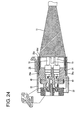
- the shielding shell 30 is so held as not to come out backward by the resilient engagement of the locking portions 30a of the shielding shell 30 and the engaging portion 20e of the housing 20 as shown in FIG. 24. Thereafter, the cover 60 is assembled and the resilient or rubber boot 70 is mounted in the order as already described in the first embodiment.
- the end of the shielding member 11 is to be or can be secured to the shielding shell 30 before the shielding shell 30 is mounted into the housing 20. It is not necessary to process the end of the shielded conductor path B and connect the shielded conductor path B and the shielding shell 30 at an assembling site, thereby reducing an operation load at the assembling site.
- the shielding shell 30 since the shielding shell 30 is held mounted in the housing 20 by the resilient engagement of the locking portions 30a of the shielding shell 30 and the engaging portion 20e of the housing 20, the shielding shell 30 can be mounted into the housing 20 through a one-touch operation. Thus, it does not take much time to mount the shielding shell 30 into the housing 20.
Landscapes
- Engineering & Computer Science (AREA)
- Manufacturing & Machinery (AREA)
- Details Of Connecting Devices For Male And Female Coupling (AREA)
Abstract
Description
- The present invention relates to a shielded connector.
- A known end processing construction for a shielded conductor path obtained by surrounding a plurality of wires together by a tubular shielding member made of a braided wire is such that terminal fittings connected with ends of the respective wires are accommodated in a housing, a cable formed by twisting an end portion of the shielding member is branched off from the conductor path, and a grounding terminal is secured to an end of the branched cable and connected with a grounding member such as a body or an equipment. A construction for processing an end of a shielded conductor path obtained by surrounding a plurality of wires together by a tubular shielding member made of a braided wire, the construction being provided with a grounding circuit branched off from the conductor path, is disclosed e.g. in Japanese Unexamined Patent Publication No. H08-96919.
- In the case of a construction for branching a grounding circuit off from a conductor path as in the prior art, an operation of connecting a grounding terminal is necessary in addition to an operation of connecting a housing having terminal fittings accommodated therein with a mating housing. This increases the number of operation steps, thereby presenting poor operability.
- The present invention was developed in view of the above problem and an object thereof is to improve operability.
- This object is solved according to the invention by a shielded connector according to claim 1. Preferred embodiments of the invention are subject of the dependent claims.
- According to the invention, there is provided a shielded connector to be connected with a shielded conductor path obtained by surrounding one or more, preferably a plurality of wires together by a tubular shielding member preferably made of a braided wire, comprising:
- a housing for at least partly accommodating one or more terminal fittings connected with ends of the wires,
- a conductive (preferably metallic) shielding shell disposed in or on the housing in such a manner as to at least partly substantially surround the terminal fittings, and
- a connecting means for connecting an end of the shielding member with the shielding shell.
-
- Since the shielding shell is provided in the housing and the end of the shielding member is or is to be connected with the shielding shell, the shielding shell can be connected with a grounding member of a mating housing when the housing is connected with the mating housing. Accordingly, it is not necessary to connect the shielding member with the grounding member in addition to a housing connecting operation.
- According to a preferred embodiment of the invention, the shielding shell is formed to be integral to the housing by insert molding.
- Since the shielding shell and the housing are integrally formed by insert molding, the number of assembling steps at an assembling site can be reduced as compared to a construction in which a shielding shell is assembled into an already molded housing.
- Preferably, the connecting means includes a metallic tubular connecting member to which the end of the shielding member is secured by crimping.
- The shielding member made of a braided wire is easy to deform. By securing the end of the shielding member to the metallic tubular connecting member, the shielding member can be easily and securely connected with the shielding shell.
- Further preferably, a connecting portion of the shielding shell with the tubular connecting member is tubular, and the tubular connecting portion of the shielding shell and the tubular connecting member are connected with the circumferential surfaces thereof at least partly placed one over the other or at least partly overlapped along the longitudinal direction.
- Since the shielding shell and the tubular connecting member are connected with the circumferential surfaces thereof placed one over the other or at least partly overlapped along the longitudinal direction, a large contact area can be ensured and no clearance is defined along longitudinal direction between the shielding shell and the tubular connecting member to provide a stable shielding performance.
- Most preferably, a cover for at least partly covering a connecting part of the shielding shell and the connecting means is mounted on or at the housing.
- The connecting part of the shielding shell and the connecting means is protected from the interference of an external matter and the like by being at least partly covered by the cover mounted on the housing.
- According to a further preferred embodiment of the invention, the connecting means includes:
- a shielding jacket preferably formed by braiding metallic fine wires into a substantially tubular shape,
- a first crimping ring to be at least partly arranged on the outer circumferential surface of one end portion of the shielding jacket and crimped or folded or bent with the one end portion of the shielding jacket connected with the end of the shielding member, and
- a second crimping ring to be at least partly arranged on the outer circumferential surface of the other end portion of the shielding jacket and crimped with the other end portion of the shielding jacket at least partly fitted on the end of the shielding member.
-
- The shielding member can be connected with the shielding shell via the shielding jacket.
- Preferably, the connecting means includes a crimping ring to be at least partly arranged on the outer circumferential surface of the end of the shielding member and crimped or bent or folded with the end portion of the shielding member at least partly fitted on the end portion of the shielding shell.
- The shielding member can be directly connected with the shielding shell.
- Further preferably, the connecting means includes a crimping ring to be at least partly arranged on the outer circumferential surface of the end portion of the shielding member and crimped with the end of the shielding member at least partly fitted on the end portion of the shielding shell, and the shielding shell is at least partly mounted into or onto the housing later.
- Since the shielding shell is mounted into or onto the housing later, the shielding shell can be exchanged.
- Further preferably, the end portion of the shielding member is secured to the shielding shell by the crimping ring before the shielding shell is at least partly mounted into or onto the housing.
- Since the end of the shielding member is secured to the shielding shell before the shielding shell is at least partly mounted into or onto the housing, it is not necessary to process an end of the shielded conductor path and connect the shielded conductor path and the shielding shell at an assembling site.
- Still further preferably, the shielding shell includes at least one locking portion resiliently engageable with at lest one engaging portion of the housing, and the shielding shell is held at least partly mounted in the housing by the resilient engagement of the locking portion and the engaging portion.
- Since the shielding shell is held mounted in the housing by the resilient engagement of the locking portion of the shielding shell and the engaging portion of the housing, the shielding shell can be mounted into the housing through a one-touch operation.
- Most preferably, an insulating short-circuit preventing portion at least partly surrounding the wires is provided at a side of the housing inward of the shielding shell.
- Since the insulating short-circuit preventing portion surrounding the wires is provided at the side of the housing inward of the shielding shell, even if a coating portion of the wire should be peeled off to be exposed for a certain reason, an electrical connection of such a conductor with the shielding shell can be avoided by the contact of the conductor with the short-circuit preventing portion.
- These and other objects, features and advantages of the present invention will become more apparent upon reading of the following detailed description of preferred embodiments and accompanying drawings. It should be understood that even though embodiments are separately described, single features thereof may be combined to additional embodiments.
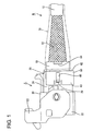
- FIG. 1 is a side view of a first embodiment,
- FIG. 2 is a section of the first embodiment,
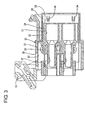
- FIG. 3 is a section of a housing,
- FIG. 4 is a side view of the housing,
- FIG. 5 is a rear view of the housing,
- FIG. 6 is a plan view of the housing,
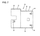
- FIG. 7 is a section of a shielding shell,
- FIG. 8 is a side view of the shielding shell,
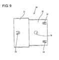
- FIG. 9 is a plan view of the shielding shell,
- FIG. 10 is a bottom view of the shielding shell,
- FIG. 11 is a front view of the shielding shell,
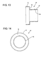
- FIG. 12 is a side view of a tubular connecting member,
- FIG. 13 is a section of the tubular connecting member,
- FIG. 14 is a rear view of the tubular connecting member,
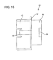
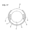
- FIG. 15 is a side view of a cover,
- FIG. 16 is a section of the cover,
- FIG. 17 is a front view of the cover,
- FIG. 18 is a rear view of the cover,
- FIG. 19 is a section of a second embodiment,
- FIG. 20 is a section of a third embodiment,
- FIG. 21 is an exploded section of a fourth embodiment,
- FIG. 22 is a section showing a state before a shielded conductor path is assembled with the shielding shell,
- FIG. 23 is a section showing a state before the shielding shell is assembled with the housing,
- FIG. 24 is a section of an assembled shielded connector of the fourth embodiment,
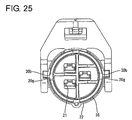
- FIG. 25 is a front view of the assembled shielded connector of the fourth embodiment, and
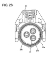
- FIG. 26 is a rear view of the assembled shielded connector of the fourth embodiment.
-
- Hereinafter, a first preferred embodiment of the present invention is described with reference to FIGS. 1 to 18. In the following description, longitudinal direction and forward and backward directions mean the same.
- A shielded conductor path B connected with a shielded connector A of this embodiment is described. A shielded conductor path B is such that e.g. three wires 10 (the number of the wires is three in this embodiment, but may be one, two, four or more) are at least partly surrounded together by a
tubular shielding member 11. Eachwire 10 preferably is a non-shielded wire having a known construction of surrounding a conductor by an insulation coating. The shieldingmember 11 preferably is made of a braided wire formed by braiding a multitude of metal fine wires into a mesh, and has such a flexibility as to be extendible both in longitudinal direction and in radial directions. However, the shieldingmember 11 may be made by a conductive foil, a conductive sheath, or the like shielding material having sufficient shielding properties. Asheath 12 is mounted on the outer circumferential surface of the shieldingmember 11. - The shielded connector A is or is to be connected with an end of the shielded conductor path B, and provided with a
housing 20, one or moreterminal fittings 40, a shieldingshell 30, a substantially tubular connectingmember 50, a connecting member preferably comprising a crimpingring 55, acover 60 and a resilient orrubber boot 70. - The
housing 20 is made e.g. of a synthetic resin and internally formed with one or more, e.g. threecavities 21 penetrating thehousing 20 substantially in forward and backward directions. A front portion (preferably a substantially front half) of thehousing 20 is a (preferably substantially rectangular)receptacle 22, and a movable member, preferably comprising a gate-shapedlever 23, is movably provided on or in the receptacle, preferably is rotatably supported on the outer surfaces of thereceptacle 22. The lever 23 (as a preferred movable member) is a known connecting/separating means used to improve operability upon connecting thehousing 20 of this embodiment with a mating housing (not shown). A rear portion (preferably a substantially rear half) of thehousing 20 is afitting portion 24 preferably having a substantially round outer shape, wherein a rear end portion thereof serves as a (preferably substantially round) fittingtube 25 extending more backward than the rear ends of thecavities 21. - The
housing 20 is provided with the shieldingshell 30 formed to be integral to thehousing 20 preferably by insert molding upon molding thehousing 20. A front portion (preferably a substantially front half) of the shieldingshell 30 is a (preferably substantially rectangular)first tube portion 31, whereas a rear portion (preferably a substantially rear half) thereof is a (preferably substantially round)second tube portion 32. Preferably, thefirst tube portion 31 has a cross section different from the cross section of thesecond tube portion 32. Since the rectangular (first)tube portion 31 and the round (second)tube portion 32 are coupled one after the other via a stepped portion (as a preferred transitional portion), the shieldingshell 30 has higher strength and rigidity as a whole as compared to the one having a substantially constant cross section over the entire length. Accordingly, there is no possibility that the shieldingshell 30 is deformed by an injection pressure during insert molding. At least one of the upper, left and right plates of therectangular tube portion 31 is/are formed with one or moreresilient contact pieces 33. Theround tube portion 32 is formed with one or moreresilient contact pieces 34 at (e.g. four) substantially equally circumferentially spaced apart positions and one or more locking holes 35. Such a shieldingshell 30 is so at least partly embedded in thehousing 20 as to extend along the outer surface of thehousing 20, and parts of thehousing 20 at least partly enter the locking holes 35 to position and hold the shieldingshell 30 in thehousing 20 so as not to come out of thehousing 20. - The substantially
rectangular tube portion 31 is exposed along the inner circumferential surface of thereceptacle 22 and at least partly surrounds the one or more, e.g. threeterminal fittings 40 in thecavities 21 together. With thehousing 20 connected with the mating housing, theresilient contact pieces 33 of therectangular tube portion 31 are resiliently held in contact with grounding members (not shown) provided on the outer circumferential surface of the mating housing. In the case of assembling a shielding shell into an already molded housing, resilient contact pieces are permitted to undergo substantially radial resilient deformations because of a clearance defined between the shielding shell and the housing in view of a tolerance and the like. However, since the shieldingshell 30 and thehousing 20 are adhered to each other preferably by insert molding in this embodiment, no space for permitting theresilient contact pieces 33 to be resiliently deformed substantially in radial directions can be defined between the shieldingshell 30 and thehousing 20 if no measure is taken. Accordingly, in this embodiment, thereceptacle 22 is formed with one or more mold-removal holes 26 which are open in the outer surface of thereceptacle 22 in order to avoid the adherence of the material of thereceptacle 22 to theresilient contact pieces 33 during the molding (insert molding) to prevent the resilient deformations of theresilient contact pieces 33. Therefore, theresilient contact pieces 33 can be resiliently deformed substantially in radial directions. - On the other hand, the substantially
round tube portion 32 is so arranged as to at least partly surround thecavities 21 and the one or more, e.g. threeterminal fittings 40 in thecavities 21 together in thefitting portion 24 and to be substantially concentric with thefitting portion 24, and a rear end portion of theround tube portion 32 is exposed along the inner circumferential surface of thefitting tube 25. Theresilient contact pieces 34 of theround tube portion 32 are arranged at this exposed part. When thetubular connecting member 50 to be described later is at least partly fitted into thefitting tube 25, theresilient contact pieces 34 are resiliently brought substantially into contact with the (preferably substantially tubular) connectingmember 50. In the case of assembling the shielding shell into the already molded housing, the resilient contact pieces are permitted to undergo radial resilient deformations because of a clearance defined between the shielding shell and the housing in view of a tolerance and the like. However, since the shieldingshell 30 and thehousing 20 are adhered to each other preferably by insert molding in this embodiment, no space for permitting theresilient contact pieces 34 to be resiliently deformed substantially in radial directions can be defined between the shieldingshell 30 and thehousing 20 if no measure is taken. Accordingly, in this embodiment, thefitting tube 25 is formed with one or more mold-removal holes 27 which are open in the outer surface of thefitting tube 25 in order to avoid the adherence of the material of thefitting tube 25 to theresilient contact pieces 34 during the molding to prevent the resilient deformations of theresilient contact pieces 34. Therefore, theresilient contact pieces 34 can be resiliently deformed substantially in radial directions. - The female terminal fitting 40 is to be secured to an end of each
wire 10. Theterminal fitting 40 is inserted into thecavity 21 from behind and is locked by a lockingportion 21 a formed at or substantially along an inner wall of thecavity 21. Thewire 10 extending from the rear end of the terminal fitting 40 is or is to be drawn out backward from thehousing 20 by way of thefitting tube 25. - The
tubular connecting member 50 is a connecting means for connecting the shieldingmember 11 of the shielded conductor path B and the shieldingshell 30, and made of a conductive (preferably metallic) material. A front portion (preferably a substantially front one-third area) of thetubular connecting member 50 along forward and backward directions (longitudinal direction) is a (preferably substantially round) large-diameter portion 51, and a rear portion (preferably a substantially rear two-third area) of thetubular connecting member 50 is a (preferably substantially round) small-diameter portion 52 having a smaller diameter than the large-diameter portion 51 and substantially concentric with the large-diameter portion 51. The rear end of the large-diameter portion 51 and the front end of the small-diameter portion 52 are connected via a substantially concentricannular portion 53, thereby forming a step or an intermediate portion. The outer circumferential surface of the small-diameter portion 52 is lightly recessed in circumferential direction at an intermediate portion (preferably a substantially longitudinal middle position), thereby forming arecess 54 for connection, preferably crimping. The large-diameter portion 51 of such a substantially tubular connectingmember 50 is connected with the substantiallyround tube portion 32 of the shieldingshell 30 by being fitted into thefitting tube 25 of thehousing 20. - The
cover 60 is made e.g. of a synthetic resin, and a rear portion (preferably a substantially rear half) thereof is a (preferably substantially round) surroundingportion 61 preferably substantially in the form of a round tube. Anannular flange portion 62 substantially concentric with the substantially round surroundingportion 61 preferably over the substantially entire circumference and bulging out radially outward is formed at the front end of the substantially round surroundingportion 61, and an arcuate surroundingportion 63 substantially concentric with the substantially round surroundingportion 61 extends forward from an area of the outer peripheral edge of thisflange portion 62 except an upper end portion. This arcuate surroundingportion 62 is located in a front portion (preferably a substantially front half area) of thecover 60. One or more, preferably a pair of lateral (left and right) catchingportions 64 for retaining the resilient orrubber boot 70 mounted on thecover 60 are formed on the outer circumferential surface of the substantially round surroundingportion 61. The arcuate surroundingportion 63 is formed with lock holes 65 for preventing thecover 60 from being disengaged from thehousing 20. Therubber boot 70 is so mounted as to cover the end of the shielded conductor path B, and the front end thereof is at least partly fitted on the substantially round surroundingportion 61 of thecover 60. - Next, an end processing of the shielded conductor path B and a connection step of the already processed shielded conductor path B and the shielded connector A.
- Upon processing the end of the shielded conductor path B, the
sheath 12 is first removed at the end (front end) to at least partly expose the shieldingmember 11 by a specified (predetermined or predeterminable) length and then the front end of the shieldingmember 11 is removed by a specified (predetermined or predeterminable) length to expose the front ends of the one or more, e.g. threewires 10. Thereafter, thecover 60 and the substantially round crimpingring 55 are mounted in this order on the shieldingmember 11 from front, and this assembly is kept on standby at a rear position. Therefore, thetubular connecting member 50 is mounted on the threewires 10 from front, and the small-diameter portion 52 thereof is at least partly inserted into a clearance between thewires 10 and the shieldingmember 11 to slide or allow the sliding of the crimpingring 55 forward, whereby the front end of the shieldingmember 11 is held between the small-diameter portion 52 and the crimpingring 55. When the crimpingring 55 is crimped or bent or folded in this state, the front end of the shieldingmember 11 is squeezed between the small-diameter portion 52 and the crimpingring 55 and the shieldingmember 11 is caught in or at least partly enters therecess 54. In this way, the small-diameter portion 52 of thetubular connecting member 50 is electrically secured to the front end of the shieldingmember 11. Thereafter, thetubular connecting member 50 is retracted backward while the shieldingmember 11 is so deformed as to contract or deform along longitudinal direction, and theterminal fittings 40 are connected with the front ends of therespective wires 10 in this state. The end processing of the shielded conductor path B is completed in this way. - Upon connecting such a shielded conductor path B with the shielded connector A, the respective
terminal fittings 40 are first at least partly inserted into thecavities 21 and then thetubular connecting member 50 is slid forward to fit the large-diameter portion 51 thereof into thefitting tube 25 at the rear end of thehousing 20. At this time, thetubular connecting member 50 is stopped at its front end position by the at least partial contact of the front end of the large-diameter portion 51 with a back end surface 28 (surface in which the rear ends of thecavities 21 make openings) of thefitting tube 25. The large-diameter portion 51 at least partly fitted into thefitting tube 25 radially overlap theround tube portion 32 of the shieldingshell 30 substantially along its inner circumferential surface (the outer circumferential surface of the large-diameter portion 51 and the inner circumferential surface of theround tube portion 32 are opposed to or in contact with each other), and theresilient contact pieces 34 of theround tube portion 32 are resiliently brought substantially into contact with the outer circumferential surface of the large-diameter portion 51, with the result that thetubular connecting member 50 is electrically connected with the shieldingshell 30, i.e. the shieldingmember 11 and the shieldingshell 30 are electrically connected with each other. - Thereafter, the
cover 60 having been waiting on standby behind is slid forward to at least partly fit the arcuate surroundingportion 63 of thecover 60 on the fitting portion 24 (including the fitting tube 25) of thehousing 20 substantially without making any radial shaking movement. When being properly assembled, thecover 60 is stopped at its front end position by the contact of theflange portion 62 thereof with the rear end edge of thefitting tube 25, and the front edges of the lock holes 65 of thecover 60 are at least partly engaged withlock projections 29 of thehousing 20 from front, whereby thecover 60 is prevented from coming backward out of thehousing 20. As a result, thecover 60 is locked into thehousing 20. - In the above case, it does not matter even if the
tubular connecting member 50 and thecover 60 are slid forward to be assembled into thehousing 20 after thetubular connecting member 50 is assembled with thecover 60 beforehand. Then, thetubular connecting member 50 is at least partly inserted into thefitting tube 25 in a stable posture while being guided by thecover 60. - With the
cover 60 assembled, thetubular connecting member 50 is prevented from coming backward out of thehousing 20 by the contact of theannular portion 53 of thetubular connecting member 50 with theflange portion 62 of thecover 60 from front. Inside thefitting tube 25, the large-diameter portion 51 of thetubular connecting member 50 can move substantially along forward and backward directions between theback end surface 28 and theflange portion 62 of thecover 60. Theround surrounding portion 61 of thecover 60 at least partly surrounds the small-diameter portion 52 of thetubular connecting member 50 projecting backward from thehousing 20 while being radially spaced apart from the small-diameter portion 52. - After the
cover 60 is assembled, the resilient orrubber boot 70 at least partly fitted on the shielded conductor path B beforehand is slid forward to closely fit the front end of therubber boot 70 on the substantially round surroundingportion 61 of thecover 60. In this state, the inner circumferential surface of the front end of therubber boot 70 is caught by the catchingportions 64 formed on the substantially round surroundingportion 61, thereby preventing therubber boot 70 from being detached backward from thecover 60. Therubber boot 70 at least partly surrounds the shieldingmember 11 exposed by removing thesheath 12 of the shielded conductor path B. After therubber boot 70 is mounted, the rear end of therubber boot 70 is at least partly fitted on the front end of thesheath 12 and taping (not shown) is applied from the rear end of therubber boot 70 to thesheath 12, thereby uniting the rear end of therubber boot 70 and the shielded conductor path B and closing a clearance to the shielded conductor path B at the rear end of therubber boot 70 to preferably provide watertightness. In this way, the connection of the shielded conductor path B and the shielded connector A is completed. - As described above, the shielded connector A of this embodiment is provided with the
housing 20 for at least partly accommodating the one or moreterminal fittings 40, the conductive (preferably metallic) shieldingshell 30 provided in thehousing 20 to at least partly surround theterminal fittings 40 and thetubular connecting member 50 as a connecting means for connecting the end of the shieldingmember 11 and the shieldingshell 30. In other words, since the shieldingshell 30 is provided in or at thehousing 20 and the end of the shieldingmember 11 is connected with the shieldingshell 30, it is not necessary to connect the shieldingmember 11 with the grounding members in addition to the operation of connecting thehousing 20 by connecting the shieldingshell 30 with the grounding members of the mating housing when thehousing 20 is connected with the mating housing. - Since the shielding
shell 30 is formed to be integral to thehousing 20 preferably by insert molding, the number of operation steps at an assembling site can be reduced as compared to a construction in which a shielding shell is assembled into an already molded housing. - The connecting means for connecting the shielding
member 11 and the shieldingshell 30 is comprised of the conductive (metallic)tubular connecting member 50 to which the end of the shieldingmember 11 is to be secured preferably by crimping, and the crimpingring 55. This is in view of the easiness of the shieldingmember 11 preferably made of a braided wire to deform. By securing the end of the shieldingmember 11 to the (metallic)tubular connecting member 50, the connection with the shieldingshell 30 can be easily and securely made. - Further, since the substantially
round tube portion 32 as a connecting portion of the shieldingshell 30 with thetubular connecting member 50 is tubular and the substantiallyround tube portion 32 of the shieldingshell 30 and the large-diameter portion 51 of thetubular connecting member 50 are connected with the circumferential surfaces thereof at least partly placed one over the other, a large contact area can be ensured and no clearance is defined substantially along longitudinal direction between the shieldingshell 30 and thetubular connecting member 50 to provide a stable shielding performance. - The
cover 60 for at least partly, preferably fully covering the connecting part of the shieldingshell 30 and thetubular connecting member 50 is mounted on thehousing 20. The connecting part of the shieldingshell 30 and thetubular connecting member 50 can be preferably protected from the interference with an external matter or the like by thiscover 60. - Accordingly, to improve operability, a shielded connector A is provided with a
housing 20 for at least partly accommodating one or moreterminal fittings 40 to be connected with ends of one or morerespective wires 10, a conductive (preferably metallic) shieldingshell 30 provided in thehousing 20, and a substantially tubular connectingmember 50 for connecting an end of the shieldingmember 11 and the shieldingshell 30. Since the shieldingshell 30 is provided in thehousing 20 and the end of the shieldingmember 11 is connected with this shieldingshell 30, the shieldingshell 30 can be connected with grounding members of a mating housing when thehousing 20 is connected with the mating housing. Thus, it is not necessary to connect the shieldingmember 11 with the grounding members in addition to a connecting operation of thehousing 20. - A second preferred embodiment of the present invention is described with reference to FIG. 19. The
tubular connecting member 50 and thecover 60 shown in the fist embodiment are omitted from the second embodiment. Instead, the shieldingmember 11 and the shieldingshell 30 are connected via a shieldingjacket 80. In the second embodiment, no repetitive description is given on the construction, functions and effects similar or same to those of the first embodiment, in particular by using the same reference numerals. - First, changes made in the
housing 20 and the shieldingshell 30 of the first embodiment are described. A part of thefitting portion 24 of thehousing 20 arranged more radially outward than the substantiallyround tube portion 32 of the shieldingshell 30 has its rear end portion of a specified (predetermined or predeterminable) length bored preferably over the substantially entire circumference, wherefore the outer circumferential surface of the rear end of theround tube portion 32 is exposed to the outside. Thefitting tube 25 shown in the first embodiment is omitted and, accordingly, the length of the substantiallyround tube portion 32 of the shieldingshell 30 is shortened and theresilient contact pieces 34 shown in the first embodiment are also omitted. - The shielding
jacket 80 is, as a whole, a substantially tubular element formed preferably by braiding metallic fine wires, having open front and rear ends, and adapted to at least partly surround all the one ormore wires 10 together, wherein arear end 80a and afront end 80b are connected with the shieldingmember 11 and the shieldingshell 30 preferably by means of crimpingrings rear end 80a of the shieldingjacket 80 is fitted substantially around afront end 11 a of the shieldingmember 11 exposed to the outside, whereby both ends 11 a, 80a are radially placed (opposed) one over the other or at least partly overlapped along the longitudinal direction. In this state, the first crimpingring 90 preferably made of a metal is at least partly mounted on the outer circumferential surface of therear end 80a of the shieldingjacket 80 and crimped or bent or folded, whereby the shieldingjacket 80 is connected with the shieldingmember 11. A (preferably metallic) receiving ring (not shown) surrounding all thewires 10 is provided between therespective wires 10 and the shieldingmember 11 so as to receive a crimping force acting upon crimping the first crimpingring 90. - On the other hand, the
front end 80b of the shieldingjacket 80 is at least partly fitted around arear end 32a of theround tube portion 32 of the shieldingshell 30 exposed to the outside, whereby both ends 32a, 80b are radially placed (opposed) one over the other or at least partly overlapped along the longitudinal direction. In this state, the second crimpingring 91 preferably made of a metal is at least partly mounted on the outer circumferential surface of thefront end 80b of the shieldingjacket 80 and crimped or bent or folded, whereby the shieldingjacket 80 is connected with the shieldingshell 30. In this way, the shieldingmember 11 can be connected with the shieldingshell 30 via the shieldingjacket 80 in this embodiment. Further, the resilient orrubber boot 70 is so mounted as to at least partly cover the outer circumferential surface of the shieldingjacket 80. - A third preferred embodiment of the present invention is described with reference to FIG. 20. In this third embodiment, the shielding
member 11 is directly connected with the shieldingshell 30 by omitting the shieldingjacket 80 of the second embodiment. In the third embodiment, no repetitive description is given on the construction, functions and effects same or similar to those of the first and second embodiments. - The shielding
member 11 is exposed by a specified (predetermined or predeterminable) length by removing thesheath 12 and thefront end 11 a thereof is fitted at least partly around therear end 32a of the substantiallyround tube portion 32 of the shieldingshell 30 while being radially extended. Then, both ends 11 a, 32a are radially placed one over the other or at least partly overlapped along the longitudinal direction. In this state, the (metallic) crimpingring 92 is at least partly mounted on the outer circumferential surface of thefront end 11 a of the shieldingmember 11 and crimped or bent or folded, whereby the shieldingmember 11 is connected with the shieldingshell 30. In this way, since the shieldingmember 11 can be directly connected with the shieldingshell 30 in this embodiment, the number of parts can be reduced as compared to the first and second embodiments. - A fourth preferred embodiment of the present invention is described with reference to FIGS. 21 to 26. This fourth embodiment is similar to the third embodiment in that the shielding
member 11 is to be directly connected with the shieldingshell 30, but is characterized in that the shieldingshell 30 is mounted on the already moldedhousing 20 preferably from behind. In the fourth embodiment, no repetitive description is given on the construction, functions and effects same or similar to those of the first to third embodiments. - First, changes made in the
housing 20 and the shieldingshell 30 of the third embodiment are described. As shown in FIGS. 23 and 26, thefitting portion 24 of thehousing 20 is formed with anannular mounting groove 20a for permitting the at least partial entrance of the shieldingshell 30, and anouter tube portion 20b and aninner tube portion 20d are arranged at a radially outer side and a radially inner side of the mountinggroove 20a, respectively. The rear ends of theouter tube portion 20b and theinner tube portion 20d are aligned substantially at the same position, and the outer circumferential surface of theouter tube portion 20b is substantially in flush with and continuous with the outer circumferential surface of thereceptacle 22 except a part of the bottom end. - The
inner tube portion 20d has an insulating property preferably by being made of a synthetic resin material forming thehousing 20, and at least partly surrounds therespective wires 10 secured to the respectiveterminal fittings 10 together. Accordingly, if the insulation coating of thewire 10 should be peeled off to expose the conductor for a certain reason, such a conductor comes into contact with theinner tube portion 20d, thereby avoiding a direct contact with the shieldingshell 30 at least partly fitted into the mountinggroove 20a. Therefore, no electrical inconvenience occurs. In other words, theinner tube portion 20d corresponds to a preferred short-circuit preventing portion. - An
engaging portion 20e having a slanted or convergingsurface 20f sloped down or inward toward the back projects from the inner wall of the mountinggroove 20a at a side of theinner tube portion 20d. One ormore locking portions 30a of the shielding shell 30 (to be described later) are resiliently engageable with the engagingportion 20e. - On the other hand, the shielding
shell 30 is comprised of a larger (preferably substantially round)tube portion 36 arranged at a front portion (preferably substantially a front half), and a smaller (preferably substantially round)tube portion 37 arranged at a rear portion (preferably substantially a rear half), substantially concentric with and having a smaller diameter than the largerround tube portion 36. The largerround tube portion 36 and the smallerround tube portion 37 are integrally or unitarily coupled via a tapered stepped orintermediate portion 38. - The inner circumferential surfaces of the larger substantially
round tube portion 36, the steppedportion 38 and the smaller substantiallyround tube portion 37 are arranged on the outer circumferential surface of theinner tube portion 20d of thefitting portion 24, wherein the inner circumferential surface of the steppedportion 38 is held in substantially close contact with theslanted surface 20f of the engagingportion 20e. The end of the shieldingmember 11 is at least partly mounted on the outer circumferential surface of the smallerround tube portion 37, and a crimpingring 95 is crimped or bent or folded into connection with the shieldingmember 11. The length of the crimpingring 95 along forward and backward directions preferably is set to be substantially equal to that of the smallerround tube portion 37 along forward and backward directions. - The larger
round tube portion 36 is formed with one ormore split slots 30b extending substantially along forward and backward directions from the front end of the largerround tube portion 36 and circumferentially spaced apart from each other. Thehousing 20 is provided with one or moreengaging projections 20g at positions substantially corresponding to thesplit slots 30b. When the shieldingshell 30 is mounted into thehousing 20, the engagingprojections 20g are closely inserted into thesplit slots 30b to hinder the rotation of the shieldingshell 30 about its longitudinal axis. - The locking
portions 30a are provided at positions of the largerround tube portion 36 near the steppedportion 38. Therespective locking portions 30a preferably are cantilever-shaped, resiliently deformable, and arranged preferably at substantially symmetrical positions with respect to the center longitudinal axis of the largerround tube portion 36. Specifically, each lockingportion 30a is inclined inward of the largerround tube portion 36 from the front end to the rear end in its natural state. During the insertion of the shieldingshell 30 into the mountinggroove 20a, the lockingportions 30a are resiliently deformed outward by coming substantially into contact with the engagingportion 20e. When the shieldingshell 30 is mounted to a substantially proper depth, the lockingportions 30a are disengaged and resiliently restored to or toward their initial postures, thereby being engageable with the front surface of the engagingportion 20e. - Next, an assembling process of the fourth embodiment is described. First, prior to the assembling of the shielding
shell 30 into thehousing 20, the smaller substantiallyround tube portion 37 of the shieldingshell 30 is at least partly inserted between thewires 10 and the shieldingmember 11, the crimpingring 95 kept on standby at a rear position is slid forward to hold the end of the shieldingmember 11 between the smallerround tube portion 37 and the crimpingring 95. When the crimpingring 95 is crimped or bent or folded by unillustrated upper and lower molds in this state, the front end of the shieldingmember 11 is squeezed between the smallerround tube portion 37 and the crimpingring 95. Subsequently, as shown in FIG. 23, the one or moreterminal fittings 40 are secured to the front ends of therespective wires 10. In this way, there can be obtained an integral unit of the shieldingshell 30 and the shielded conductor path B. - In order to assemble the shielding
shell 30 into thehousing 20 in this state, the respectiveterminal fittings 40 are first at least partly inserted into thecavities 21 and then the shieldingshell 30 is moved forward to at least partly fit the largerround tube portion 36 into the mountinggroove 20a of thehousing 20. When the largerround tube portion 36 is pushed deeper into thehousing 20, the engagingprojections 20g of thehousing 20 at least partly enter thesplit slots 30b of the largerround tube portion 36 and the steppedportion 38 comes substantially into contact with theslanted surface 20f of thehousing 20, thereby preventing any further forward movement of the largerround tube portion 36. At this properly mounted position, the shieldingshell 30 is so held as not to come out backward by the resilient engagement of the lockingportions 30a of the shieldingshell 30 and the engagingportion 20e of thehousing 20 as shown in FIG. 24. Thereafter, thecover 60 is assembled and the resilient orrubber boot 70 is mounted in the order as already described in the first embodiment. - As described above, according to the fourth embodiment, the end of the shielding
member 11 is to be or can be secured to the shieldingshell 30 before the shieldingshell 30 is mounted into thehousing 20. It is not necessary to process the end of the shielded conductor path B and connect the shielded conductor path B and the shieldingshell 30 at an assembling site, thereby reducing an operation load at the assembling site. - Further, since the shielding
shell 30 is held mounted in thehousing 20 by the resilient engagement of the lockingportions 30a of the shieldingshell 30 and the engagingportion 20e of thehousing 20, the shieldingshell 30 can be mounted into thehousing 20 through a one-touch operation. Thus, it does not take much time to mount the shieldingshell 30 into thehousing 20. - The present invention is not limited to the above described and illustrated embodiments. For example, the following embodiments are also embraced by the technical scope of the present invention as defined by the claims. Beside the following embodiment, various changes can be made without departing from the scope and spirit of the present invention as defined by the claims.
- (1) Although the (preferably metallic) tubular connecting member is used as the connecting means for connecting the end of the shielding member and the shielding shell in the first embodiment, the end of the shielding member may be directly connected with the shielding shell preferably by welding, soldering or the like according to the present invention.
- (2) Although the shielding shell and the housing are integrally formed by insert molding in the foregoing embodiments, the shielding shell may be assembled into an already molded housing according to the present invention.
- (3) Although the shielding shell and the tubular connecting member are connected such that the circumferential surfaces thereof are substantially opposed to each other in the first embodiment, flanges may be formed at ends of the shielding shell and the tubular connecting member and the shielding shell and the tubular connecting member may be connected by bringing the flanges into abutment against each other according to the present invention.
- (4) Although the connectors having a movable member for assisting or performing connection (e.g. so-called lever-type connectors) are described in the foregoing embodiments, the present invention is also applicable to connectors of such a type as to be connected without using a lever, slider or other movable member.
- (5) In the second embodiment, the first crimping ring arranged on the outer circumferential surface of the front end of the shielding member may be crimped or bent or folded with the rear end of the shielding jacket fitted inside the front end of the shielding member.
- (6) In the fourth embodiment, the engaging portion of the housing may be resiliently deformable and the locking portions of the shielding shell may be holes into which the engaging portion is fittable.
-
-
- A
- shielded connector
- B
- shielded conductor path
- 10
- wire
- 11
- shielding member
- 11a
- end
- 20
- housing
- 20d
- inner tube portion (short-circuit preventing portion)
- 20e
- engaging surface (engaging portion)
- 30
- shielding shell
- 30a
- locking portion
- 32
- round tube portion (connecting portion)
- 32a
- end
- 40
- terminal fitting
- 50
- tubular connecting member (connecting means)
- 60
- cover
- 80
- shielding jacket
- 80a
- rear end (one end)
- 80b
- front end (other end)
- 90
- first crimping ring
- 91
- second crimping ring
- 92,95
- crimping ring
Claims (11)
- A shielded connector (A) to be connected with a shielded conductor path (B) obtained by surrounding one or more wires (10) together by a tubular shielding member (11) preferably made of a braided wire, comprising:a housing (20) for at least partly accommodating one or more terminal fittings (40) to be connected with ends of the wires (10),a conductive shielding shell (30) disposed in or on the housing (20) in such a manner as to substantially surround the terminal fittings (40), anda connecting means (50) for connecting an end of the shielding member (11) with the shielding shell (30).
- A shielded connector according to claim 1, wherein the shielding shell (30) is formed to be integral to the housing (20) by insert molding.
- A shielded connector according to claim 1 or 2, wherein the connecting means (50) includes a metallic tubular connecting member (50) to which the end of the shielding member (11) is secured by crimping.
- A shielded connector according to claim 3, wherein a connecting portion (32) of the shielding shell (30) with the tubular connecting member (50) is tubular, and the tubular connecting portion (32) of the shielding shell (30) and the tubular connecting member (50) are connected with the circumferential surfaces thereof at least partly placed one over the other.
- A shielded connector according to one or more of the preceding claims, wherein a cover (60) for at least partly covering a connecting part of the shielding shell (30) and the connecting means (50) is mounted on the housing (20).
- A shielded connector according to one or more of the preceding claims, wherein the connecting means (50) includes:a shielding jacket (80) preferably formed by braiding metallic fine wires into a substantially tubular shape,a first crimping ring (90) to be at least partly arranged on the outer circumferential surface of one end portion of the shielding jacket (80) and crimped with the one end portion (80a) of the shielding jacket (80) connected with the end of the shielding member (11), anda second crimping ring (91) to be at least partly arranged on the outer circumferential surface of the other end portion (80b) of the shielding jacket (80) and crimped with the other end portion of the shielding jacket (80) at least partly fitted on the end portion of the shielding member (11).
- A shielded connector according to one or more of the preceding claims, wherein the connecting means (50) includes a crimping ring (92) to be at least partly arranged on the outer circumferential surface of the end portion of the shielding member (11) and crimped with the end portion of the shielding member (11) at least partly fitted on the end of the shielding shell (30).
- A shielded connector according to one or more of the preceding claims, wherein the connecting means (50) includes a crimping ring (95) to be arranged on the outer circumferential surface of the end portion of the shielding member (11) and crimped with the end of the shielding member (11) at least partly fitted on the end of the shielding shell (30), and the shielding shell (30) is mounted into or onto the housing (20) later.
- A shielded connector according to claim 8, wherein the end of the shielding member (11) is secured to the shielding shell (30) by the crimping ring (95) before the shielding shell (30) is mounted into or onto the housing (20).
- A shielded connector according to claim 8 or 9, wherein the shielding shell (30) includes at least one locking portion (30a) resiliently engageable with at least one corresponding engaging portion (20e) of the housing (20), and the shielding shell (30) is held mounted in or on the housing (20) by the resilient engagement of the locking portion (30a) and the engaging portion (20e).
- A shielded connector according to any one of claims 7 to 10, wherein an insulating short-circuit preventing portion (20e) at least partly surrounding the wires (10) is provided at a side of the housing (20) inward of the shielding shell (30).
Applications Claiming Priority (6)
| Application Number | Priority Date | Filing Date | Title |
|---|---|---|---|
| JP2003425641 | 2003-12-22 | ||
| JP2003425641 | 2003-12-22 | ||
| JP2004099781 | 2004-03-30 | ||
| JP2004099781 | 2004-03-30 | ||
| JP2004174049A JP4306541B2 (en) | 2003-12-22 | 2004-06-11 | Shield connector |
| JP2004174049 | 2004-06-11 |
Publications (1)
| Publication Number | Publication Date |
|---|---|
| EP1548899A1 true EP1548899A1 (en) | 2005-06-29 |
Family
ID=34557030
Family Applications (1)
| Application Number | Title | Priority Date | Filing Date |
|---|---|---|---|
| EP04030052A Withdrawn EP1548899A1 (en) | 2003-12-22 | 2004-12-17 | A shielded connector |
Country Status (5)
| Country | Link |
|---|---|
| US (2) | US7147513B2 (en) |
| EP (1) | EP1548899A1 (en) |
| JP (1) | JP4306541B2 (en) |
| KR (1) | KR100673372B1 (en) |
| CN (1) | CN100394649C (en) |
Cited By (5)
| Publication number | Priority date | Publication date | Assignee | Title |
|---|---|---|---|---|
| EP1608045A3 (en) * | 2004-06-17 | 2006-04-05 | Sumitomo Wiring Systems, Ltd. | A shielded connector and method of connecting it with a shielded conductor path |
| WO2008012607A1 (en) * | 2006-07-27 | 2008-01-31 | Fci | Method for arranging a cable, cable and ferrule to be used in the method |
| FR2937471A1 (en) * | 2008-10-16 | 2010-04-23 | Eurocopter France | Wiring harness connecting method for rotorcraft, involves clamping braid of harness against rear part of connector, where electrical continuity between braid and part is assured using conductive ink between terminal zone of braid and part |
| EP2109194A3 (en) * | 2008-04-10 | 2011-09-14 | Weidmüller Interface GmbH & Co. KG | Connector with an attached shielded cable |
| WO2014060790A1 (en) * | 2012-10-15 | 2014-04-24 | Delphi International Operations Luxembourg S.À.R.L. | Electrical connection system |
Families Citing this family (29)
| Publication number | Priority date | Publication date | Assignee | Title |
|---|---|---|---|---|
| JP4306541B2 (en) * | 2003-12-22 | 2009-08-05 | 住友電装株式会社 | Shield connector |
| JP4527019B2 (en) * | 2005-07-13 | 2010-08-18 | 住友電装株式会社 | Shield connector |
| WO2008109109A1 (en) * | 2007-03-06 | 2008-09-12 | Tyco Electronics Corporation | High voltage shielded electrical connector assembly |
| KR100993098B1 (en) * | 2008-12-18 | 2010-11-08 | 엘에스전선 주식회사 | Fixing crimp band, method for joining shielded connector and bulk knitted shield using same, shielded connector structure |
| KR101538806B1 (en) * | 2009-03-16 | 2015-07-22 | 타이코에이엠피(유) | Shielded braided shell cover |
| JP5267341B2 (en) * | 2009-06-05 | 2013-08-21 | 住友電装株式会社 | Shield connector |
| JP5399800B2 (en) * | 2009-07-17 | 2014-01-29 | 矢崎総業株式会社 | Waterproof structure |
| KR101151901B1 (en) * | 2010-09-17 | 2012-05-31 | 주식회사 경신 | Connector and method for making same |
| JP5833300B2 (en) * | 2010-11-11 | 2015-12-16 | 矢崎総業株式会社 | connector |
| JP5743664B2 (en) * | 2011-04-13 | 2015-07-01 | 矢崎総業株式会社 | Shield connector |
| US9318849B2 (en) * | 2011-04-14 | 2016-04-19 | Yazaki Corporation | Shielded connector |
| JP5771071B2 (en) * | 2011-06-02 | 2015-08-26 | 矢崎総業株式会社 | Shield braid connection structure |
| JP5768618B2 (en) | 2011-09-21 | 2015-08-26 | 住友電装株式会社 | Wire harness terminal waterproof structure |
| WO2014096890A1 (en) * | 2012-12-18 | 2014-06-26 | Delphi International Operations Luxembourg S.À.R.L. | Electrical connector device |
| JP5990454B2 (en) * | 2012-12-25 | 2016-09-14 | 矢崎総業株式会社 | Shield connector structure |
| JP6062874B2 (en) * | 2014-02-13 | 2017-01-18 | トヨタ自動車株式会社 | Terminal block |
| WO2015164538A1 (en) | 2014-04-23 | 2015-10-29 | Tyco Electronics Corporation | Electrical connector with shield cap and shielded terminals |
| JP2016015272A (en) * | 2014-07-03 | 2016-01-28 | 矢崎総業株式会社 | Shield connector |
| DE102015003061A1 (en) * | 2015-03-10 | 2016-09-15 | Sumitomo Wiring Systems, Ltd. | Shielded wiring, shielding member and method of making shielded wiring |
| US9666982B1 (en) * | 2016-04-25 | 2017-05-30 | Te Connectivity Corporation | Electrical connector having latch release collar |
| JP6387059B2 (en) * | 2016-09-16 | 2018-09-05 | 矢崎総業株式会社 | Terminal fitting fixing structure and wire harness |
| BE1025878B1 (en) * | 2018-01-08 | 2019-08-06 | Phoenix Contact Gmbh & Co Kg | Cable shield contacting device and electrical connector |
| JP6897621B2 (en) * | 2018-03-30 | 2021-06-30 | 株式会社オートネットワーク技術研究所 | Wire harness |
| CN108986971B (en) * | 2018-07-02 | 2020-11-24 | 上海微小卫星工程中心 | A cable shielding device |
| JP7051232B2 (en) * | 2018-07-30 | 2022-04-11 | 矢崎総業株式会社 | Shielded connector |
| CN109616834A (en) * | 2018-12-13 | 2019-04-12 | 上海航天科工电器研究院有限公司 | One kind having the quick locking wire water-proof connector of shielding construction |
| JP7256456B2 (en) * | 2019-08-08 | 2023-04-12 | 株式会社オートネットワーク技術研究所 | wire harness |
| JP6993393B2 (en) * | 2019-10-31 | 2022-01-13 | 矢崎総業株式会社 | Lever type connector |
| CN113991381B (en) * | 2021-10-12 | 2024-04-02 | 长缆电工科技股份有限公司 | Automatic high-voltage line connecting and disconnecting device and control method |
Citations (5)
| Publication number | Priority date | Publication date | Assignee | Title |
|---|---|---|---|---|
| US3775732A (en) * | 1972-02-11 | 1973-11-27 | Hitemp Wires Inc | Shield termination device |
| US4891022A (en) * | 1986-12-22 | 1990-01-02 | Amp Incorporated | Shielded data connector |
| EP0921603A1 (en) * | 1997-10-15 | 1999-06-09 | Pouyet S.A. | Wall socket at least partially shielded and process of connecting an electrical cable |
| US6012950A (en) * | 1996-12-17 | 2000-01-11 | Siemens Aktiengesellschaft | High-polarity shielded cable plug |
| EP1006622A1 (en) * | 1998-12-04 | 2000-06-07 | Labinal | Shielded electrical connection cable |
Family Cites Families (18)
| Publication number | Priority date | Publication date | Assignee | Title |
|---|---|---|---|---|
| US3646496A (en) * | 1969-07-30 | 1972-02-29 | Williams Instruments | Electrical cable connector and grounding means |
| US4059330A (en) * | 1976-08-09 | 1977-11-22 | John Schroeder | Solderless prong connector for coaxial cable |
| US4236779A (en) * | 1978-05-01 | 1980-12-02 | Bunker Ramo Corporation | EMI Shielded cable and connector assembly |
| US4399318A (en) * | 1981-12-10 | 1983-08-16 | The Bendix Corporation | EMI Shielding enclosure for a cable connector |
| US4433206A (en) * | 1981-12-10 | 1984-02-21 | The Bendix Corporation | EMI Shielded connector assembly |
| US5180316A (en) * | 1991-03-25 | 1993-01-19 | Molex Incorporated | Shielded electrical connector |
| JP2772324B2 (en) * | 1992-11-11 | 1998-07-02 | 矢崎総業株式会社 | Shield connector |
| JP2580724Y2 (en) * | 1993-01-22 | 1998-09-17 | 矢崎総業株式会社 | Shield connector for device direct mounting |
| US5460544A (en) * | 1993-05-26 | 1995-10-24 | Yazaki Corporation | Electro-magnetically shielded connector |
| JPH0896919A (en) | 1994-09-20 | 1996-04-12 | Hitachi Ltd | Shielded cable terminal connection device |
| JP3032939B2 (en) * | 1994-11-29 | 2000-04-17 | 矢崎総業株式会社 | Shield connector |
| US5906513A (en) * | 1997-03-20 | 1999-05-25 | Woodhead Industries Inc. | Shielded, molded electrical connector |
| US6231392B1 (en) * | 1997-10-01 | 2001-05-15 | Berg Technology, Inc. | Cable interconnection |
| JPH11126656A (en) * | 1997-10-21 | 1999-05-11 | Yazaki Corp | Shield connector |
| KR20030092395A (en) * | 2002-05-29 | 2003-12-06 | 현대자동차주식회사 | Electromagnetic interference shield connector of electric vehicle |
| JP4306541B2 (en) * | 2003-12-22 | 2009-08-05 | 住友電装株式会社 | Shield connector |
| JP4238787B2 (en) * | 2004-06-17 | 2009-03-18 | 住友電装株式会社 | Shield connector |
| ATE485013T1 (en) * | 2006-11-20 | 2010-11-15 | Septrx Inc | DEVICE FOR PREVENTING THE UNDESIRABLE FLOW OF EMBOLIS FROM THE VEINS INTO THE ARTERIES |
-
2004
- 2004-06-11 JP JP2004174049A patent/JP4306541B2/en not_active Expired - Lifetime
- 2004-12-17 EP EP04030052A patent/EP1548899A1/en not_active Withdrawn
- 2004-12-20 US US11/018,069 patent/US7147513B2/en not_active Expired - Fee Related
- 2004-12-22 CN CNB2004101045805A patent/CN100394649C/en not_active Expired - Fee Related
- 2004-12-22 KR KR1020040110590A patent/KR100673372B1/en not_active Expired - Fee Related
-
2006
- 2006-12-07 US US11/635,092 patent/US7226317B2/en not_active Expired - Fee Related
Patent Citations (5)
| Publication number | Priority date | Publication date | Assignee | Title |
|---|---|---|---|---|
| US3775732A (en) * | 1972-02-11 | 1973-11-27 | Hitemp Wires Inc | Shield termination device |
| US4891022A (en) * | 1986-12-22 | 1990-01-02 | Amp Incorporated | Shielded data connector |
| US6012950A (en) * | 1996-12-17 | 2000-01-11 | Siemens Aktiengesellschaft | High-polarity shielded cable plug |
| EP0921603A1 (en) * | 1997-10-15 | 1999-06-09 | Pouyet S.A. | Wall socket at least partially shielded and process of connecting an electrical cable |
| EP1006622A1 (en) * | 1998-12-04 | 2000-06-07 | Labinal | Shielded electrical connection cable |
Cited By (8)
| Publication number | Priority date | Publication date | Assignee | Title |
|---|---|---|---|---|
| EP1608045A3 (en) * | 2004-06-17 | 2006-04-05 | Sumitomo Wiring Systems, Ltd. | A shielded connector and method of connecting it with a shielded conductor path |
| WO2008012607A1 (en) * | 2006-07-27 | 2008-01-31 | Fci | Method for arranging a cable, cable and ferrule to be used in the method |
| EP2109194A3 (en) * | 2008-04-10 | 2011-09-14 | Weidmüller Interface GmbH & Co. KG | Connector with an attached shielded cable |
| EP2109194B1 (en) | 2008-04-10 | 2018-06-13 | Weidmüller Interface GmbH & Co. KG | Electrical connection with a connector and an cable attached thereto |
| FR2937471A1 (en) * | 2008-10-16 | 2010-04-23 | Eurocopter France | Wiring harness connecting method for rotorcraft, involves clamping braid of harness against rear part of connector, where electrical continuity between braid and part is assured using conductive ink between terminal zone of braid and part |
| WO2014060790A1 (en) * | 2012-10-15 | 2014-04-24 | Delphi International Operations Luxembourg S.À.R.L. | Electrical connection system |
| CN104798260A (en) * | 2012-10-15 | 2015-07-22 | 德尔福国际业务卢森堡公司 | Electrical connection system |
| CN104798260B (en) * | 2012-10-15 | 2018-11-23 | 德尔福国际业务卢森堡公司 | Electrical connection system |
Also Published As
| Publication number | Publication date |
|---|---|
| US7226317B2 (en) | 2007-06-05 |
| CN1638208A (en) | 2005-07-13 |
| KR100673372B1 (en) | 2007-01-24 |
| JP2005317485A (en) | 2005-11-10 |
| CN100394649C (en) | 2008-06-11 |
| US20070082534A1 (en) | 2007-04-12 |
| KR20050063742A (en) | 2005-06-28 |
| JP4306541B2 (en) | 2009-08-05 |
| US20050136738A1 (en) | 2005-06-23 |
| US7147513B2 (en) | 2006-12-12 |
Similar Documents
| Publication | Publication Date | Title |
|---|---|---|
| US7226317B2 (en) | Shielded connector | |
| US11664629B2 (en) | Assembly comprising a connector and a cable | |
| US5965847A (en) | Shield connector | |
| EP1608045B1 (en) | A shielded connector and method of connecting it with a shielded conductor path | |
| JP2595406Y2 (en) | Plug type multi-pole connector | |
| CN112490735B (en) | Connector and assembly for automotive applications | |
| EP1689046B1 (en) | A shielded connector | |
| EP1098397B1 (en) | Equipment direct-mounting type shield electric connector assembly | |
| EP2761700B1 (en) | Shield connector and method of assembling shield connector | |
| US11411352B2 (en) | Connector for automotive applications | |
| US20230335956A1 (en) | Shielded electrical connector for automotive applications and method of assembling thereof | |
| US11799247B2 (en) | Connector, and connector structure including inner conductor and outer conductor | |
| EP3783754A1 (en) | Connector for automotive applications | |
| JPH06203919A (en) | Shielding connector | |
| EP1744409B1 (en) | A shielded connector and method of connecting it with a shielded cable | |
| EP3249757B1 (en) | Waterproof connector | |
| EP0993075A2 (en) | Electrical connector with metallic jacket | |
| JP4677318B2 (en) | Shield connector and method of manufacturing shield connector | |
| CN113196589A (en) | Connector structure and method for manufacturing connector structure | |
| JP2000100525A (en) | Shield connector and method of manufacturing the same | |
| EP1003244B1 (en) | A shielded connector and a method for connecting a shielded connector with a shielded cable |
Legal Events
| Date | Code | Title | Description |
|---|---|---|---|
| PUAI | Public reference made under article 153(3) epc to a published international application that has entered the european phase |
Free format text: ORIGINAL CODE: 0009012 |
|
| 17P | Request for examination filed |
Effective date: 20041230 |
|
| AK | Designated contracting states |
Kind code of ref document: A1 Designated state(s): AT BE BG CH CY CZ DE DK EE ES FI FR GB GR HU IE IS IT LI LT LU MC NL PL PT RO SE SI SK TR |
|
| AX | Request for extension of the european patent |
Extension state: AL BA HR LV MK YU |
|
| AKX | Designation fees paid |
Designated state(s): DE FR |
|
| 17Q | First examination report despatched |
Effective date: 20070420 |
|
| STAA | Information on the status of an ep patent application or granted ep patent |
Free format text: STATUS: THE APPLICATION IS DEEMED TO BE WITHDRAWN |
|
| 18D | Application deemed to be withdrawn |
Effective date: 20140701 |