EP1548881A1 - Antenne à surfaces rayonnantes planes et téléphone comportant une telle antenne - Google Patents
Antenne à surfaces rayonnantes planes et téléphone comportant une telle antenne Download PDFInfo
- Publication number
- EP1548881A1 EP1548881A1 EP04293082A EP04293082A EP1548881A1 EP 1548881 A1 EP1548881 A1 EP 1548881A1 EP 04293082 A EP04293082 A EP 04293082A EP 04293082 A EP04293082 A EP 04293082A EP 1548881 A1 EP1548881 A1 EP 1548881A1
- Authority
- EP
- European Patent Office
- Prior art keywords
- plane
- antenna according
- antenna
- partial area
- radiation
- Prior art date
- Legal status (The legal status is an assumption and is not a legal conclusion. Google has not performed a legal analysis and makes no representation as to the accuracy of the status listed.)
- Granted
Links
- 230000005855 radiation Effects 0.000 claims abstract description 32
- 239000002184 metal Substances 0.000 claims description 5
- 238000005516 engineering process Methods 0.000 claims description 4
- 238000000034 method Methods 0.000 description 2
- 230000009286 beneficial effect Effects 0.000 description 1
- 230000007547 defect Effects 0.000 description 1
- 230000001419 dependent effect Effects 0.000 description 1
- 230000033001 locomotion Effects 0.000 description 1
- 238000005259 measurement Methods 0.000 description 1
- 238000004377 microelectronic Methods 0.000 description 1
Images


Classifications
-
- H—ELECTRICITY
- H01—ELECTRIC ELEMENTS
- H01Q—ANTENNAS, i.e. RADIO AERIALS
- H01Q1/00—Details of, or arrangements associated with, antennas
- H01Q1/12—Supports; Mounting means
- H01Q1/22—Supports; Mounting means by structural association with other equipment or articles
- H01Q1/24—Supports; Mounting means by structural association with other equipment or articles with receiving set
- H01Q1/241—Supports; Mounting means by structural association with other equipment or articles with receiving set used in mobile communications, e.g. GSM
- H01Q1/242—Supports; Mounting means by structural association with other equipment or articles with receiving set used in mobile communications, e.g. GSM specially adapted for hand-held use
- H01Q1/243—Supports; Mounting means by structural association with other equipment or articles with receiving set used in mobile communications, e.g. GSM specially adapted for hand-held use with built-in antennas
-
- H—ELECTRICITY
- H01—ELECTRIC ELEMENTS
- H01Q—ANTENNAS, i.e. RADIO AERIALS
- H01Q21/00—Antenna arrays or systems
- H01Q21/28—Combinations of substantially independent non-interacting antenna units or systems
-
- H—ELECTRICITY
- H01—ELECTRIC ELEMENTS
- H01Q—ANTENNAS, i.e. RADIO AERIALS
- H01Q9/00—Electrically-short antennas having dimensions not more than twice the operating wavelength and consisting of conductive active radiating elements
- H01Q9/04—Resonant antennas
- H01Q9/0407—Substantially flat resonant element parallel to ground plane, e.g. patch antenna
- H01Q9/0421—Substantially flat resonant element parallel to ground plane, e.g. patch antenna with a shorting wall or a shorting pin at one end of the element
Definitions
- the present invention relates to a surface-type antenna radiant planes.
- the invention proposes in particular an antenna of this type comprising radiating surfaces whose functions of certain parts are suitable to be reversed according to the conditions of use.
- PIFA Planar Inverted-F Antenna
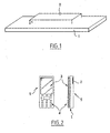
- plane antenna of type F inverted which comprise, as illustrated in FIG. mass 1 and a plane conductive surface 2 which is superimposed on this plane mass 1, and extends to the right and parallel to it.
- a montage has a resonant wavelength that is a function of the dimensions of the plane conductive surface 2 and the height which separates it from its plane of mass 1.
- an antenna of this type is easily integrated in a mobile phone 5 having a keyboard 4 and a screen 3.
- the ground plane 1 is constituted by the printed circuit board located inside the housing of the telephone 5, behind the screen 3 and the keyboard 4.
- the radiating surface 2 is generally placed at the rear of the housing of the phone 5.
- this kind of antenna offers good performance radiation, especially in far-field measurement, while producing locally a near field weaker than whip antennas or helical antennas also known to those skilled in the art.
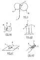
- a defect of this kind antenna is the dissymmetry of the radiation pattern.
- the radiation lobe 20 on the side of the radiation surface 2 is more important than the lobe 10 on the side of the ground plane 1.
- the difference between the two lobes 10 and 20 is of the order of about 3 dB.
- This asymmetry is more or less pronounced following the immediate surroundings of the antenna, ie the presence of parts metal, the dimensions of the mobile, etc.
- the radiation lobe 20 is larger on the opposite side to the the user's head 6 and the lobe 10 is weaker on the side of the head 6 of the the user.
- FIGS. 4B to 4D show use cases in which which asymmetry gives rise to problems in the operation of the phone 5.
- FIGS 2 to 4D show a one-piece telephone. We understands however that the situation is the same for phones with two shutters or "clam" telephones according to the English terminology generally employed by those skilled in the art.
- FIGS. 5A to 5C also illustrate a telephone case 5 to particular architecture, for example a clam phone with an opening at 360 ° and having two flaps referenced by 51 and 52.
- the surface 2 is located in the pane referenced by 52.
- the flap 51 of the telephone 5 is for example placed on a table 8, the flap 52 being in the closed position on the flap 51. surface 52 is therefore well located with respect to table 8 and the Phone 5 link with the network base station is good.
- Some known techniques propose to solve the problem bad link with the base station of the network by positioning two PIFA antennas in the phone, an antenna being located at the front of the housing of the phone, and another at the back of the housing.
- Switching means make it possible to operating one or the other of the antennas according to the configuration and the position of the phone. So the phone always has a antenna well placed for its emission / reception.
- EP 1 160999 discloses an antenna which allows a switching of certain parts of the antenna, but does not allow a control of the front / back radiation of the antenna with respect to housing of the phone.
- a large constant mass plane is arranged under the all switchable parts.
- the switchable parts overlap the large plane of mass over their entire area.
- One of the aims of the invention is to propose an antenna and a telephone such an antenna overcomes at least one of the disadvantages of antennas and telephones of the prior art.
- One of the aims of the invention is in particular to propose an antenna and a phone that can have a good connection with a radio station network basis regardless of the phone's configuration or position use.
- One of the aims of the invention is, in particular, to propose a antenna and a phone having a symmetrical behavior with respect to a base station of the network.
- One of the aims of the invention is to propose a telephone having only one antenna.
- the invention proposes an antenna according to the claim 1.
- the invention thus proposes a transmitting / receiving antenna having a ground plane and at least one plane surface of radiation, characterized in that it comprises a partial zone of mass reference, at least two flat surfaces extending parallel to it and switching means connecting electrically the reference partial area to alternately one of the planar surfaces, thus defining a switching between a first configuration and a second configuration, the first configuration corresponding to a situation in which one of the flat surfaces constitutes the radiation surface, the entire mass plane comprising then the reference partial area and the other flat surface, the second configuration corresponding to a situation in which the radiation surface of the first configuration is connected electrically to the reference partial area to form the plane of whole mass, the other flat surface then playing the role of surface of radiation.
- the invention also relates to a telephone comprising such a antenna.
- the invention has many advantages.
- the antenna radiates mostly towards the front part or mainly towards the rear part the housing of the phone.
- the antenna shown in FIG. 6A comprises a ground plane 1 and at minus one flat plane of radiation.
- the antenna more precisely comprises a zone partial reference 60 mass and at least two surfaces 61 and 62 planes extending parallel to the reference partial area 60 of mass.
- the surface 61 is located in the extension of the zone 60, while the surface 62 is remote from the zone 60 according to a perpendicular direction.
- the antenna also comprises switching means 63 electrically connecting the reference partial area 60 to alternatively one of the flat surfaces 61 and 62.
- the switching means 63 thus define a switching between a first configuration and a second configuration.
- the first configuration is visible in Figure 6A and corresponds to a situation in which one of the flat surfaces - here the surface 62 - constitutes the radiation surface. So this surface 62 that in the first configuration sets the radiation frequencies of the phone.
- the whole mass plane 1 then has in the first configuration the reference partial area 60 and the other flat surface, here the surface 61.
- the means 63 connect electrically in A and B the zone 60 and the In contrast, the means 63 electrically isolate the zone 60 and the zone 62 in this configuration.
- the second configuration is visible in Figure 6B and corresponds as for it to a situation in which the surface of radiation of the first configuration, namely the surface 62, is electrically connected to the reference partial area 60 to form the plane 1 of the whole mass.
- the electrical junction is located at A 'and B'.
- the other flat surface 61 now plays the role of surface of radiation for the antenna.
- the surface 61 is then electrically isolated from zone 60.
- the radiant surface is, depending on whether the first configuration is selected or the second configuration is selected, either at the front of the housing of a mobile phone in which an antenna according to the invention is placed either at the rear of the housing.
- the flat surfaces 61 and 62 able to be switched to form either a part of the ground plane or the radiant surface are not located at the right of the partial zone 60 forming the ground plane.
- the flat surfaces 61 and 62 do not overlap the partial area 60.
- the flat surfaces 61 and 62 can in certain modes of achievement overlap the partial area 60 over a negligible area in front of their dimension, so that the general behavior of the antenna is not affected and that depending on the switching, the antenna radiates predominantly towards the front part or mainly towards the rear part of the housing of the phone.
- the area of overlap of a surface 61 or 62 is less than half the area of each of said surfaces 61 or 62, advantageously the overlap area is between 20 and 0% of the area of each of said surfaces 61 or 62. As indicated, very preferentially, there is no overlap.
- the partial area 60 of mass does not block the radiation of any flat surface whatever the chosen configuration, the partial area 60 also plays its role of mass in the two possible configurations.
- the area of the possible zone of overlap is negligible area in front of the size of the partial area 60.
- Figure 7 shows another possible arrangement of surfaces 61 and 62 as well as zone 60.
- zone 60 is disposed behind a screen 3 of a telephone 5.
- the two flat surfaces 61 and 62 are preferentially, but not necessarily, of the same dimensions, and are located symmetrically with respect to a plane containing the area 60 mass reference.
- the partial zone 60 of mass reference is constituted by all or part of a printed circuit fit to be placed in a phone.
- the flat surfaces 61 and 62 are plates metal.
- the switching means 63 are able to form circuits open electric or closed electrical circuits.
- the means 63 comprise the junctions 81 to 86 connecting the zone 60 at both surfaces 61 and 62.
- junctions 81 and 82 between the zone 60 and the surface 61 are closed circuits, while junctions 83 and 84 between area 60 and surface 62 are open circuits.
- junction 85 for connecting the point of attack 87 to the surface radiation 62 is therefore a closed circuit, while the symmetrical junction with respect to the zone 60 is an open circuit.
- junctions 81 and 82 between the zone 60 and surface 61 are open circuits, while junctions 83 and 84 between zone 60 and surface 62 are closed circuits.
- junction 85 for connecting the point of attack 87 to the surface radiation 61 is therefore a closed circuit, whereas the symmetrical junction with respect to the zone 60 is an open circuit.
- the switching means 63 may comprise at least one PIN diode.
- the switching means 63 may comprise at least one active diode that is less expensive.
- the switching means 63 can include electromechanical microsystems of MEMS technology (or "micro-electronic mechanical system” according to the English terminology generally used by those skilled in the art). Microsystems form relays for switching an antenna configuration to another by alternately connecting the surfaces 61 or 62 to the area 60.
- the invention applies equally to a monoblock telephone or to a phone with two parts.
- the invention improves the radiated performances of the phone, regardless of the configuration or position of use of the phone, thanks to a single antenna.
- the invention is therefore compact and inexpensive.
- FIGS. 9A and 9B and 10A and 10B thus show that the surface radiant is always located in the best situation, namely the back housing, to have a better reception and a better reception.
- FIG. 9A thus shows that when a monobloc telephone is placed on a table, the surface 62 is the radiation surface, while my figure 9B shows that when the phone 5 is used at the head 6 of a user, the surface 61 is the radiation surface.
- FIG. 10A shows that when the flap 52 is above the flap 51, the surface 62 is the radiating surface
- FIG. 10B shows that when the flap 52 is below the flap 51, the surface 61 becomes the radiation surface.
- the radiation surface is so not hidden in the phone and is located at the back of the housing.
Landscapes
- Engineering & Computer Science (AREA)
- Computer Networks & Wireless Communication (AREA)
- Telephone Set Structure (AREA)
- Support Of Aerials (AREA)
Abstract
Description
- la zone partielle de référence de masse est constituée par tout ou partie d'un circuit imprimé apte à être placé dans un téléphone ;
- les deux surfaces planes sont de mêmes dimensions et sont situées symétriquement par rapport à un plan contenant la zone partielle de référence de masse ;
- les surfaces planes sont des plaques métalliques ;
- les moyens de commutation sont aptes à former des circuits électriques ouvert ou des circuits électriques fermés ;
- les moyens de commutation comportent au moins une diode PIN ;
- les moyens de commutation comportent au moins une diode active ;
- les moyens de commutation comportent des microsystèmes électromécaniques de technologie MEMS.
- la figure 1, déjà discutée, représente schématiquement une antenne de type PIFA conforme à un état de la technique connu ;
- la figure 2, également déjà discutée, est une représentation schématique de face et de profil d'un téléphone connu;
- la figure 3, déjà commentée, est une représentation schématique d'un graphe du diagramme de rayonnement d'une antenne connue ;
- les figures 4A à AD, déjà commentées, sont des représentations schématiques de positions d'utilisation d'un téléphone connu ;
- les figures 5A à 5C, déjà commentée, sont des représentations schématiques de configurations d'utilisation d'un téléphone à deux volets connu ;
- les figures 6A et 6B sont des représentations schématiques des configurations d'une antenne selon l'invention ;
- la figure 7 montre une disposition possible des surfaces planes ainsi que de la zone partielle de référence de masse d'une antenne selon l'invention ;
- la figure 8 représente schématiquement les jonctions entre les deux surfaces planes et la zone partielle de référence ;
- les figures 9A à 10B montre la situation de la surface rayonnante dans plusieurs positions d'utilisations et pour plusieurs configurations de téléphones.
Claims (10)
- Antenne d'émission/réception comportant un plan (1) de masse et au moins une surface (2) plane de rayonnement, une zone partielle (60) de référence de masse, au moins deux surfaces (61, 62) planes s'étendant parallèlement à la zone partielle (60) et des moyens (63) de commutation reliant électriquement la zone partielle (60) de référence à alternativement une (61, 62) des surfaces planes, définissant ainsi une commutation entre une première configuration et une deuxième configuration, la première configuration correspondant à une situation dans laquelle une (62) des surfaces planes constitue la surface (2) de rayonnement, le plan (1) de masse entier comportant alors la zone partielle (60) de référence et l'autre (61) surface plane, la deuxième configuration correspondant quant à elle à une situation dans laquelle la surface (62) de rayonnement de la première configuration est reliée électriquement à la zone (60) partielle de référence pour former le plan (1) de masse entier, l'autre surface plane (61) jouant alors désormais le rôle de surface (2) de rayonnement, caractérisée en ce que les surfaces planes chevauchent la zone partielle (60) au plus sur une aire négligeable devant l'aire desdites surfaces (61, 62).
- Antenne selon la revendication 1, caractérisée en ce que la zone partielle de référence (60) de masse est constituée par tout ou partie d'un circuit imprimé apte à être placé dans un téléphone (5).
- Antenne selon l'une des revendications 1 ou 2, caractérisée en ce que les deux surfaces (61, 62) planes sont de mêmes dimensions et sont situées symétriquement par rapport à un plan contenant la zone (60) partielle de référence de masse.
- Antenne selon l'une des revendications 1 à 3, caractérisée en ce que les surfaces planes (61, 62) sont des plaques métalliques.
- Antenne selon l'une des revendications 1 à 4, caractérisée en ce que les moyens de commutation (63) sont aptes à former des circuits électriques ouverts ou des circuits électriques fermés.
- Antenne selon la revendication 5, caractérisée en ce que les moyens de commutation (63) comportent au moins une diode PIN.
- Antenne selon la revendication 5, caractérisée en ce que les moyens de commutation (63) comportent au moins une diode active.
- Antenne selon la revendication 5, caractérisée en ce que les moyens de commutation (63) comportent des microsystèmes électromécaniques de technologie MEMS.
- Téléphone (5) monobloc, caractérisé en ce qu'il comporte une antenne selon l'une des revendications précédentes.
- Téléphone (5) comportant deux volets (51, 52), caractérisé en ce qu'il comporte une antenne selon l'une des revendications précédentes.
Applications Claiming Priority (2)
| Application Number | Priority Date | Filing Date | Title |
|---|---|---|---|
| FR0315252 | 2003-12-23 | ||
| FR0315252A FR2864352B1 (fr) | 2003-12-23 | 2003-12-23 | Attennea surfaces rayonnantes planes et telephone comportant une telle antenne. |
Publications (2)
| Publication Number | Publication Date |
|---|---|
| EP1548881A1 true EP1548881A1 (fr) | 2005-06-29 |
| EP1548881B1 EP1548881B1 (fr) | 2007-10-03 |
Family
ID=34531333
Family Applications (1)
| Application Number | Title | Priority Date | Filing Date |
|---|---|---|---|
| EP20040293082 Expired - Lifetime EP1548881B1 (fr) | 2003-12-23 | 2004-12-22 | Antenne à surfaces rayonnantes planes et téléphone comportant une telle antenne |
Country Status (4)
| Country | Link |
|---|---|
| EP (1) | EP1548881B1 (fr) |
| DE (1) | DE602004009275T2 (fr) |
| ES (1) | ES2291836T3 (fr) |
| FR (1) | FR2864352B1 (fr) |
Citations (2)
| Publication number | Priority date | Publication date | Assignee | Title |
|---|---|---|---|---|
| EP0680161B1 (fr) * | 1994-04-28 | 1998-07-08 | Nec Corporation | Dispositif radio avec une pluralité d'antennes |
| EP1160999A1 (fr) * | 2000-06-03 | 2001-12-05 | Robert Bosch Gmbh | Agencement d'antenne pour un téléphone mobile |
-
2003
- 2003-12-23 FR FR0315252A patent/FR2864352B1/fr not_active Expired - Fee Related
-
2004
- 2004-12-22 ES ES04293082T patent/ES2291836T3/es not_active Expired - Lifetime
- 2004-12-22 EP EP20040293082 patent/EP1548881B1/fr not_active Expired - Lifetime
- 2004-12-22 DE DE200460009275 patent/DE602004009275T2/de not_active Expired - Lifetime
Patent Citations (2)
| Publication number | Priority date | Publication date | Assignee | Title |
|---|---|---|---|---|
| EP0680161B1 (fr) * | 1994-04-28 | 1998-07-08 | Nec Corporation | Dispositif radio avec une pluralité d'antennes |
| EP1160999A1 (fr) * | 2000-06-03 | 2001-12-05 | Robert Bosch Gmbh | Agencement d'antenne pour un téléphone mobile |
Also Published As
| Publication number | Publication date |
|---|---|
| FR2864352B1 (fr) | 2006-08-18 |
| DE602004009275T2 (de) | 2008-07-24 |
| DE602004009275D1 (de) | 2007-11-15 |
| EP1548881B1 (fr) | 2007-10-03 |
| FR2864352A1 (fr) | 2005-06-24 |
| ES2291836T3 (es) | 2008-03-01 |
Similar Documents
| Publication | Publication Date | Title |
|---|---|---|
| WO2002011236A1 (fr) | Antenne a surface(s) rayonnante(s) plane(s) et telephone portable comportant une telle antenne | |
| FR2860927A1 (fr) | Antenne interne de faible volume | |
| EP1415059A1 (fr) | Poignee d'ouvrant pour vehicule automobile | |
| FR2722626A1 (fr) | Antenne pour dispositif de communication | |
| FR2724793A1 (fr) | Antenne a composants multiples et methode de realisation de celle-ci | |
| EP2792017A1 (fr) | Dispositif d'antenne et procédé de configuration d'antenne | |
| WO2002084791A1 (fr) | Radiotelephone portatif | |
| EP1548881B1 (fr) | Antenne à surfaces rayonnantes planes et téléphone comportant une telle antenne | |
| FR2754942A1 (fr) | Systeme antennaire pour poste radiotelephone portatif | |
| EP1701406B1 (fr) | Antenne planaire dont les dimensions du plan de masse sont modifiables | |
| EP1577975B1 (fr) | Téléphone en deux parties comportant une antenne à surfaces planes rayonnantes | |
| EP1808930B1 (fr) | Téléphone mobile avec antenne intégrée suffisamment distante de la tête de l'utilisateur | |
| EP2772985B1 (fr) | Système de fixation d'un radôme plan sur le réflecteur concave d'une antenne | |
| EP0821837B1 (fr) | Connecteur interrupteur ou inverseur coaxial miniature a plongeur et lames de contact passives | |
| FR2867904A1 (fr) | Systeme de reception et de decodage d'ondes electromagnetiques muni d'une antenne compacte | |
| EP2561619B1 (fr) | Dispositif de protection contre des ondes électromagnétiques | |
| EP1548877B1 (fr) | Antenne à surface(s) rayonnante(s) plane(s) multibande et téléphone portable comportant une telle antenne | |
| EP1750325B1 (fr) | Antenne multibandes | |
| EP3085114B1 (fr) | Système comprenant un appareil électronique et un support | |
| EP2673945B1 (fr) | Systeme de communication telephonique comprenant une station d'accueil comportant un logement destine a recevoir un telephone mobile | |
| EP1987565B1 (fr) | Terminal de telephonie cellulaire et de reception multimedia | |
| EP1509966A1 (fr) | Antenne multi-frequence integree pour telephone mobile | |
| EP1111713A1 (fr) | Téléphone portable avec une antenne et un plan de masse | |
| FR2863406A1 (fr) | Antenne pour terminal de radiocommunication | |
| FR2823601A1 (fr) | Radiotelephone portatif a antenne a plaque |
Legal Events
| Date | Code | Title | Description |
|---|---|---|---|
| PUAI | Public reference made under article 153(3) epc to a published international application that has entered the european phase |
Free format text: ORIGINAL CODE: 0009012 |
|
| AK | Designated contracting states |
Kind code of ref document: A1 Designated state(s): AT BE BG CH CY CZ DE DK EE ES FI FR GB GR HU IE IS IT LI LT LU MC NL PL PT RO SE SI SK TR |
|
| AX | Request for extension of the european patent |
Extension state: AL BA HR LV MK YU |
|
| 17P | Request for examination filed |
Effective date: 20051202 |
|
| GRAP | Despatch of communication of intention to grant a patent |
Free format text: ORIGINAL CODE: EPIDOSNIGR1 |
|
| AKX | Designation fees paid |
Designated state(s): DE ES GB IT |
|
| GRAS | Grant fee paid |
Free format text: ORIGINAL CODE: EPIDOSNIGR3 |
|
| RAP1 | Party data changed (applicant data changed or rights of an application transferred) |
Owner name: SAGEM COMMUNICATION |
|
| GRAA | (expected) grant |
Free format text: ORIGINAL CODE: 0009210 |
|
| AK | Designated contracting states |
Kind code of ref document: B1 Designated state(s): DE ES GB IT |
|
| REG | Reference to a national code |
Ref country code: GB Ref legal event code: FG4D Free format text: NOT ENGLISH |
|
| REF | Corresponds to: |
Ref document number: 602004009275 Country of ref document: DE Date of ref document: 20071115 Kind code of ref document: P |
|
| GBT | Gb: translation of ep patent filed (gb section 77(6)(a)/1977) |
Effective date: 20071207 |
|
| REG | Reference to a national code |
Ref country code: ES Ref legal event code: FG2A Ref document number: 2291836 Country of ref document: ES Kind code of ref document: T3 |
|
| PLBE | No opposition filed within time limit |
Free format text: ORIGINAL CODE: 0009261 |
|
| STAA | Information on the status of an ep patent application or granted ep patent |
Free format text: STATUS: NO OPPOSITION FILED WITHIN TIME LIMIT |
|
| 26N | No opposition filed |
Effective date: 20080704 |
|
| REG | Reference to a national code |
Ref country code: DE Ref legal event code: R082 Ref document number: 602004009275 Country of ref document: DE Representative=s name: PATENT- UND RECHTSANWAELTE BARDEHLE PAGENBERG, DE |
|
| REG | Reference to a national code |
Ref country code: DE Ref legal event code: R081 Ref document number: 602004009275 Country of ref document: DE Owner name: APPLE INC., CUPERTINO, US Free format text: FORMER OWNER: SAGEM MOBILES, PARIS, FR Effective date: 20111026 Ref country code: DE Ref legal event code: R082 Ref document number: 602004009275 Country of ref document: DE Representative=s name: BARDEHLE PAGENBERG PARTNERSCHAFT MBB PATENTANW, DE Effective date: 20111026 Ref country code: DE Ref legal event code: R082 Ref document number: 602004009275 Country of ref document: DE Representative=s name: BARDEHLE PAGENBERG PARTNERSCHAFT PATENTANWAELT, DE Effective date: 20111026 Ref country code: DE Ref legal event code: R081 Ref document number: 602004009275 Country of ref document: DE Owner name: APPLE INC., US Free format text: FORMER OWNER: SAGEM MOBILES, PARIS, FR Effective date: 20111026 |
|
| REG | Reference to a national code |
Ref country code: GB Ref legal event code: 732E Free format text: REGISTERED BETWEEN 20120412 AND 20120418 |
|
| REG | Reference to a national code |
Ref country code: GB Ref legal event code: 732E Free format text: REGISTERED BETWEEN 20120419 AND 20120425 |
|
| REG | Reference to a national code |
Ref country code: GB Ref legal event code: 732E Free format text: REGISTERED BETWEEN 20120426 AND 20120502 |
|
| PGFP | Annual fee paid to national office [announced via postgrant information from national office to epo] |
Ref country code: DE Payment date: 20191210 Year of fee payment: 16 |
|
| PGFP | Annual fee paid to national office [announced via postgrant information from national office to epo] |
Ref country code: IT Payment date: 20191209 Year of fee payment: 16 |
|
| PGFP | Annual fee paid to national office [announced via postgrant information from national office to epo] |
Ref country code: ES Payment date: 20200102 Year of fee payment: 16 Ref country code: GB Payment date: 20191219 Year of fee payment: 16 |
|
| REG | Reference to a national code |
Ref country code: DE Ref legal event code: R119 Ref document number: 602004009275 Country of ref document: DE |
|
| GBPC | Gb: european patent ceased through non-payment of renewal fee |
Effective date: 20201222 |
|
| PG25 | Lapsed in a contracting state [announced via postgrant information from national office to epo] |
Ref country code: IT Free format text: LAPSE BECAUSE OF NON-PAYMENT OF DUE FEES Effective date: 20201222 |
|
| PG25 | Lapsed in a contracting state [announced via postgrant information from national office to epo] |
Ref country code: DE Free format text: LAPSE BECAUSE OF NON-PAYMENT OF DUE FEES Effective date: 20210701 Ref country code: GB Free format text: LAPSE BECAUSE OF NON-PAYMENT OF DUE FEES Effective date: 20201222 |
|
| REG | Reference to a national code |
Ref country code: ES Ref legal event code: FD2A Effective date: 20220222 |
|
| PG25 | Lapsed in a contracting state [announced via postgrant information from national office to epo] |
Ref country code: ES Free format text: LAPSE BECAUSE OF NON-PAYMENT OF DUE FEES Effective date: 20201223 |