EP1548784A2 - Interlocking apparatus of a leading under voltage trip mechanism for manual motor starter - Google Patents
Interlocking apparatus of a leading under voltage trip mechanism for manual motor starter Download PDFInfo
- Publication number
- EP1548784A2 EP1548784A2 EP04030154A EP04030154A EP1548784A2 EP 1548784 A2 EP1548784 A2 EP 1548784A2 EP 04030154 A EP04030154 A EP 04030154A EP 04030154 A EP04030154 A EP 04030154A EP 1548784 A2 EP1548784 A2 EP 1548784A2
- Authority
- EP
- European Patent Office
- Prior art keywords
- trip device
- motor starter
- handle
- manual motor
- undervoltage trip
- Prior art date
- Legal status (The legal status is an assumption and is not a legal conclusion. Google has not performed a legal analysis and makes no representation as to the accuracy of the status listed.)
- Granted
Links
Images


Classifications
-
- H—ELECTRICITY
- H01—ELECTRIC ELEMENTS
- H01H—ELECTRIC SWITCHES; RELAYS; SELECTORS; EMERGENCY PROTECTIVE DEVICES
- H01H71/00—Details of the protective switches or relays covered by groups H01H73/00 - H01H83/00
-
- H—ELECTRICITY
- H01—ELECTRIC ELEMENTS
- H01H—ELECTRIC SWITCHES; RELAYS; SELECTORS; EMERGENCY PROTECTIVE DEVICES
- H01H83/00—Protective switches, e.g. circuit-breaking switches, or protective relays operated by abnormal electrical conditions otherwise than solely by excess current
- H01H83/12—Protective switches, e.g. circuit-breaking switches, or protective relays operated by abnormal electrical conditions otherwise than solely by excess current operated by voltage falling below a predetermined value, e.g. for no-volt protection
-
- H—ELECTRICITY
- H01—ELECTRIC ELEMENTS
- H01H—ELECTRIC SWITCHES; RELAYS; SELECTORS; EMERGENCY PROTECTIVE DEVICES
- H01H71/00—Details of the protective switches or relays covered by groups H01H73/00 - H01H83/00
- H01H71/10—Operating or release mechanisms
- H01H71/1009—Interconnected mechanisms
-
- H—ELECTRICITY
- H01—ELECTRIC ELEMENTS
- H01H—ELECTRIC SWITCHES; RELAYS; SELECTORS; EMERGENCY PROTECTIVE DEVICES
- H01H71/00—Details of the protective switches or relays covered by groups H01H73/00 - H01H83/00
- H01H71/10—Operating or release mechanisms
- H01H71/12—Automatic release mechanisms with or without manual release
- H01H71/46—Automatic release mechanisms with or without manual release having means for operating auxiliary contacts additional to the main contacts
-
- H—ELECTRICITY
- H01—ELECTRIC ELEMENTS
- H01H—ELECTRIC SWITCHES; RELAYS; SELECTORS; EMERGENCY PROTECTIVE DEVICES
- H01H71/00—Details of the protective switches or relays covered by groups H01H73/00 - H01H83/00
- H01H71/10—Operating or release mechanisms
- H01H71/50—Manual reset mechanisms which may be also used for manual release
- H01H71/56—Manual reset mechanisms which may be also used for manual release actuated by rotatable knob or wheel
Definitions
- the present invention relates to an interlocking apparatus of a leading undervoltage trip device for a manual motor starter, and more particularly, to an interlocking apparatus of a leading undervoltage trip device for a manual motor starter, which can extend a lifetime of the undervoltage trip device and improve user convenience.
- a detection section for detecting a fault current
- a switching section operated by a detection signal from the detection section
- a contact section interlocked with the operation of the switching mechanism section to open or close a current path
- an arc extinguishing section for extinguishing an arc generated when contacts of the contact section are opened.
- a rotary type handle is provided to turn on the circuit breaker.
- accessory devices for transmitting a signal indicative of an operational state of the circuit breaker to the outside and thereby informing a user of the operational state of the circuit breaker, transmitting a signal inputted from the outside to the circuit breaker, etc. are coupled to a frame of the circuit breaker.
- the accessory devices include an undervoltage trip device for transmitting to the outside a signal indicating that a voltage lower than a rated voltage is applied to the circuit breaker, a remote control trip device for tripping the circuit breaker through remote control, and an alarm device or an indicating device for visually or audibly informing a user of the operational states (such as an ON state, an OFF state and a TRIP state) of the circuit breaker.
- an undervoltage trip device for transmitting to the outside a signal indicating that a voltage lower than a rated voltage is applied to the circuit breaker
- a remote control trip device for tripping the circuit breaker through remote control
- an alarm device or an indicating device for visually or audibly informing a user of the operational states (such as an ON state, an OFF state and a TRIP state) of the circuit breaker.
- one or more of various accessory devices is optionally on the frame of the circuit breaker.
- various methods are disclosed in the art, such as a method using the movement of a crossbar arranged in the circuit breaker, a method using the movement of a shift lever arranged in the circuit breaker, a method using the rotational displacement of the handle, and so forth.
- FIG. 1 is a perspective view illustrating an example of a circuit breaker according to the conventional art.
- a rotary type handle 2 is installed on the body 1 of the motor protection circuit breaker which is also called a manual motor starter.
- An undervoltage trip device 10 serving as an accessory device is coupled to a side of the body 1 of the manual motor starter.
- the undervoltage trip device 10 functions to trip the body 1 of the manual motor starter upon application of an undervoltage below the rated voltage.
- FIGS. 2a and 2b are perspective views taken at different angles, illustrating an interlocking mechanism between a conventional undervoltage trip device 10 and the body 1 of the manual motor starter.
- the reference numeral 2 designates a handle, 3 a handle wing lever, 4 a rotation plate, 10 an undervoltage trip device, and 19 a crossbar projection of the undervoltage trip device 10.
- FIG. 3 is a view illustrating an operating structure which is interlocked with a handle 2 of the body 1 of the manual motor starter for operating the conventional undervoltage trip device 10.
- a wing lever 3 being a separate interlocked lever of the undervoltage trip device is installed to be operated only in an interval between an OFF position and a TRIP position which corresponds to 0° ⁇ 45°.
- a separate mechanism capable of allowing and interrupting internal power application to the undervoltage trip device 10 by way of the handle wing lever 3 of the body 1 of the manual motor starter.
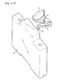
- FIG. 4 is a structural view illustrating an inner structure of the conventional undervoltage trip device 10.
- the inner structure includes a movable core 12, an undervoltage trip device coil 13, a movable core cap 14, a crossbar rotation shaft 15, fixed contacts 16, a crossbar 17, movable contacts 18, and a crossbar projection 19.
- the interlocked structure of the conventional undervoltage trip device 10 is constructed in a manner such that, only when the user manipulates the handle 2 to use the body 1 of the m tract motor starter, the undervoltage trip device 10 can operate in a leading manner.
- Detailed operation of the undervoltage trip device 10 and the body 1 of the manual motor starter is disclosed in U.S. Patent No. 6,326,871 issued on August 6, 1998.
- the leading undervoltage trip device 10 suffers from defects in that, since it is more expensive than a general undervoltage trip device, it cannot help but have a limited user group. Also, in order to interlock the undervoltage trip device 10, since the interlocked lever structure operating only in the interval between the OFF position and the TRIP position which corresponds to 0° ⁇ 45° must be provided to the body 1 of the manual motor starter, a cost for manufacturing the body 1 of the manual motor starter increases.
- an object of the present invention is to provide an interlocking apparatus of a leading undervoltage trip device for a manual motor starter, in which a lever section for interlocking the leading undervoltage trip device with a power transmitting member of a handle for operating a switching section of the body of the manual motor starter is integrated with the power transmitting member, so that parts are not added to the body of the manual motor starter and only a user using the leading undervoltage trip device bears expenses for the corresponding function, thereby reducing a manufacturing cost and a purchase price of a manual motor starter.
- an interlocking apparatus of a leading undervoltage trip device for a manual motor starter comprising: a rotatable handle for allowing a user to manually manipulate the manual motor starter to ON or OFF position; a handle power transmitting member concentrically connected to the handle to be integrally rotated with the handle and having a gear portion; and a lever portion extending in a direction perpendicular to an axis of the handle power transmitting member, to be interlocked with the leading undervoltage trip device.
- FIGS. 5a and 5b are perspective views taken at opposing angles, illustrating an interlocking mechanism between an undervoltage trip device 100 and the body 1 (see FIG. 1) of a manual motor starter, in accordance with an embodiment of the present invention.
- An interlocking apparatus of a leading undervoltage trip device 100 for a manual motor starter comprises a rotatable handle 42 for allowing a user to manually manipulate the manual motor starter to ON or OFF positions; a handle power transmitting member 30 concentrically connected to the handle 42 to be integrally rotated with the handle 42 and having a gear portion; and a lever portion 20 extending in a direction perpendicular to an axis of the handle power transmitting member 30, to be interlocked with the leading undervoltage trip device 100.
- the body 1 of the manual motor starter is omitted.
- the undervoltage trip device 100 is coupled to a side of the body 1 of the manual motor starter and has a lever projection 32 for receiving power from the lever section 20. If an undervoltage is applied to the undervoltage trip device 100, a switching mechanism section of the body 1 of the manual motor starter is tripped by power transmitted through an interlocked lever 34.
- an operating switch 50 for applying electric power to the undervoltage trip device 100 is provided to the upper end of the undervoltage trip device 100.
- the undervoltage trip device 100 is operated as it is without being changed in its operation state.
- the lever section 20 is rotated by 90° from the OFF position where it comes into contact with the lever projection 32 of the undervoltage trip device 100, to be separated from the lever projection 32 of the undervoltage trip device 100.
- the undervoltage trip device 100 operates independently of the body 1 of the manual motor starter. That is to say, if the user presses the operation switch 50 for applying electric power to the undervoltage trip device 100, the undervoltage trip device 100 is maintained in a turned-on state, and if the user presses again the operation switch 50, the undervoltage trip device 100 is turned off.
- the switching mechanism section of the body 1 of the manual motor starter which is interlocked with the projection of the interlocked lever 34 is displaced to a trip position, through the movement of a lever rotated by elastic force of a spring and the movement of the interlocked lever 34 which is raised and lowered while being interlocked with the lever.
- the interlocking apparatus of the leading undervoltage trip device for the manual motor starter is constructed in a manner such that, when the body 1 of the manual motor starter is not used, the interlocking apparatus is interlocked with the handle 42 of the body 1 of the manual motor starter to automatically interrupt electric power application to the undervoltage trip device 100.
- the interlocking apparatus of the leading undervoltage trip device for the manual motor starter extends a lifetime of the undervoltage trip device, and removes convenience caused when the user installs and manages a separate undervoltage trip device operating switch, thereby improving user convenience.
- the interlocking apparatus of a leading undervoltage trip device for a manual motor starter provides advantages in that, since a lever portion for interlocking the leading undervoltage trip device with a power transmitting member of a handle for operating a switching mechanism section of the body of the manual motor starter is integrated with the power transmitting member, separate parts are not added to the body of the manual motor starter, and, since only the undervoltage trip device can perform an undervoltage trip function, only a user using the undervoltage trip device bears expenses for the corresponding function, whereby it is possible to reduce a manufacturing cost and a purchase price of a manual motor starter.
Landscapes
- Breakers (AREA)
- Connection Of Motors, Electrical Generators, Mechanical Devices, And The Like (AREA)
- Driving Mechanisms And Operating Circuits Of Arc-Extinguishing High-Tension Switches (AREA)
Abstract
Description
a handle power transmitting member concentrically connected to the handle to be integrally rotated with the handle and having a gear portion; and
a lever portion extending in a direction perpendicular to an axis of the handle power transmitting member, to be interlocked with the leading undervoltage trip device.
Claims (1)
- An interlocking apparatus of a leading under voltage trip device for a manual motor starter, comprising:a rotatable handle for allowing a user to manually manipulate the manual motor starter to ON or OFF position;a handle power transmitting member concentrically connected to the handle to be integrally rotated with the handle and having a gear portion; anda lever portion extending in a direction perpendicular to an axis of the handle power transmitting member, to be interlocked with the leading undervoltage trip device.
Applications Claiming Priority (2)
| Application Number | Priority Date | Filing Date | Title |
|---|---|---|---|
| KR10-2003-0097672A KR100516944B1 (en) | 2003-12-26 | 2003-12-26 | Interlocking structure of lead starting under voltage trip gear |
| KR2003097672 | 2003-12-26 |
Publications (3)
| Publication Number | Publication Date |
|---|---|
| EP1548784A2 true EP1548784A2 (en) | 2005-06-29 |
| EP1548784A3 EP1548784A3 (en) | 2006-05-03 |
| EP1548784B1 EP1548784B1 (en) | 2011-05-11 |
Family
ID=34545916
Family Applications (1)
| Application Number | Title | Priority Date | Filing Date |
|---|---|---|---|
| EP04030154A Expired - Lifetime EP1548784B1 (en) | 2003-12-26 | 2004-12-20 | Interlocking apparatus of a leading under voltage trip mechanism for manual motor starter |
Country Status (7)
| Country | Link |
|---|---|
| US (1) | US20050140475A1 (en) |
| EP (1) | EP1548784B1 (en) |
| JP (1) | JP2005197250A (en) |
| KR (1) | KR100516944B1 (en) |
| CN (1) | CN1312720C (en) |
| AT (1) | ATE509362T1 (en) |
| ES (1) | ES2366027T3 (en) |
Families Citing this family (6)
| Publication number | Priority date | Publication date | Assignee | Title |
|---|---|---|---|---|
| KR100516943B1 (en) * | 2003-12-26 | 2005-09-23 | 엘에스산전 주식회사 | Structure of breaking apparatus for trip error protection of motor protected breaker and method of operating thereof |
| JP4830595B2 (en) * | 2006-04-07 | 2011-12-07 | 富士電機機器制御株式会社 | Circuit breaker |
| KR101078916B1 (en) | 2010-03-22 | 2011-11-01 | 엘에스산전 주식회사 | Under voltage trip mechanism for mold cased circuit breaker |
| KR101278501B1 (en) * | 2011-12-30 | 2013-07-02 | 엘에스산전 주식회사 | Circuit breaker provided with a mechanical trip mechanism |
| CN103280384B (en) * | 2013-06-02 | 2015-08-05 | 浙江正泰电器股份有限公司 | Device for under-voltage releasing equipment |
| CN114334502B (en) * | 2022-01-27 | 2025-07-25 | 苏州未来电器股份有限公司 | Interlocking structure of padlock and manual lock of electric operating mechanism |
Citations (2)
| Publication number | Priority date | Publication date | Assignee | Title |
|---|---|---|---|---|
| US6326871B1 (en) | 1997-12-05 | 2001-12-04 | Siemens Aktiengesellschaft | Switchgear unit of a switching device and a coupled leading auxiliary switch |
| DE10218526A1 (en) | 2001-04-27 | 2002-10-31 | Fuji Electric Co Ltd | Switch device for use with undervoltage circuit breaker, has drive lever which is held towards drive spring when handle is in switch-off position |
Family Cites Families (5)
| Publication number | Priority date | Publication date | Assignee | Title |
|---|---|---|---|---|
| DE19754071C1 (en) * | 1997-12-05 | 1999-07-15 | Siemens Ag | Switchgear unit with leading auxiliary switch |
| DE19812503C1 (en) * | 1998-03-21 | 1999-12-09 | Moeller Gmbh | Rotary circuit breaker with leading auxiliary switch |
| US6194983B1 (en) * | 1999-08-30 | 2001-02-27 | Eaton Corporation | Molded case circuit breaker with current flow indicating handle mechanism |
| JP4058895B2 (en) * | 2000-10-02 | 2008-03-12 | 富士電機機器制御株式会社 | Handle operating mechanism of circuit breaker |
| JP4186409B2 (en) * | 2000-10-30 | 2008-11-26 | 富士電機機器制御株式会社 | Circuit breaker |
-
2003
- 2003-12-26 KR KR10-2003-0097672A patent/KR100516944B1/en not_active Expired - Fee Related
-
2004
- 2004-12-20 EP EP04030154A patent/EP1548784B1/en not_active Expired - Lifetime
- 2004-12-20 ES ES04030154T patent/ES2366027T3/en not_active Expired - Lifetime
- 2004-12-20 AT AT04030154T patent/ATE509362T1/en active
- 2004-12-21 US US11/016,911 patent/US20050140475A1/en not_active Abandoned
- 2004-12-24 JP JP2004373848A patent/JP2005197250A/en active Pending
- 2004-12-27 CN CNB2004101049365A patent/CN1312720C/en not_active Expired - Lifetime
Patent Citations (2)
| Publication number | Priority date | Publication date | Assignee | Title |
|---|---|---|---|---|
| US6326871B1 (en) | 1997-12-05 | 2001-12-04 | Siemens Aktiengesellschaft | Switchgear unit of a switching device and a coupled leading auxiliary switch |
| DE10218526A1 (en) | 2001-04-27 | 2002-10-31 | Fuji Electric Co Ltd | Switch device for use with undervoltage circuit breaker, has drive lever which is held towards drive spring when handle is in switch-off position |
Also Published As
| Publication number | Publication date |
|---|---|
| JP2005197250A (en) | 2005-07-21 |
| CN1312720C (en) | 2007-04-25 |
| CN1637994A (en) | 2005-07-13 |
| US20050140475A1 (en) | 2005-06-30 |
| EP1548784A3 (en) | 2006-05-03 |
| EP1548784B1 (en) | 2011-05-11 |
| ES2366027T3 (en) | 2011-10-14 |
| KR20050066390A (en) | 2005-06-30 |
| KR100516944B1 (en) | 2005-09-23 |
| ATE509362T1 (en) | 2011-05-15 |
Similar Documents
| Publication | Publication Date | Title |
|---|---|---|
| JP2002133994A (en) | Circuit breaker | |
| EP2028670B1 (en) | Spring charging device of air circuit breaker | |
| EP1544885B1 (en) | Handle apparatus for a manual motor starter | |
| EP2492944B1 (en) | Circuit breaker | |
| JPH09223447A (en) | Control and transmission device for protection switch equipment | |
| RU2741568C1 (en) | Circuit breaker for protection against leakage current | |
| EP1548784B1 (en) | Interlocking apparatus of a leading under voltage trip mechanism for manual motor starter | |
| US8525057B2 (en) | Switching unit for a circuit breaker having a rocker lever | |
| EP1515351B1 (en) | Circuit breaker handle block | |
| US5594399A (en) | Protective switching device | |
| US6476337B2 (en) | Auxiliary switch actuation arrangement | |
| JP4029664B2 (en) | Circuit breaker | |
| KR100357206B1 (en) | display for earth leakage circuit breaker | |
| KR200477251Y1 (en) | Main contact position indicating mechanism for molded case circuit breaker | |
| CA2042278C (en) | Circuit breaker positive trip indication spring | |
| JP5217020B2 (en) | Circuit breaker switching mechanism | |
| CN221427655U (en) | Circuit breaker assembly | |
| US5317295A (en) | Molded case circuit breaker trip-to-test button | |
| KR101926043B1 (en) | Interlock apparatus for air circuit breaker | |
| KR200377717Y1 (en) | Disconnector structure | |
| KR200427820Y1 (en) | Circuit breakers with isolation | |
| KR200311946Y1 (en) | linkage of signal lever in circuit breaker | |
| JP2005085498A (en) | Circuit breaker externally attached switch unit | |
| KR200402418Y1 (en) | Emergency trip device of GIS motor spring mechanism | |
| CN120545146A (en) | A RCCB type leakage tripping mechanism and leakage protector based on leakage accessories |
Legal Events
| Date | Code | Title | Description |
|---|---|---|---|
| PUAI | Public reference made under article 153(3) epc to a published international application that has entered the european phase |
Free format text: ORIGINAL CODE: 0009012 |
|
| AK | Designated contracting states |
Kind code of ref document: A2 Designated state(s): AT BE BG CH CY CZ DE DK EE ES FI FR GB GR HU IE IS IT LI LT LU MC NL PL PT RO SE SI SK TR |
|
| AX | Request for extension of the european patent |
Extension state: AL BA HR LV MK YU |
|
| PUAL | Search report despatched |
Free format text: ORIGINAL CODE: 0009013 |
|
| AK | Designated contracting states |
Kind code of ref document: A3 Designated state(s): AT BE BG CH CY CZ DE DK EE ES FI FR GB GR HU IE IS IT LI LT LU MC NL PL PT RO SE SI SK TR |
|
| AX | Request for extension of the european patent |
Extension state: AL BA HR LV MK YU |
|
| 17P | Request for examination filed |
Effective date: 20061013 |
|
| AKX | Designation fees paid |
Designated state(s): AT ES IT TR |
|
| REG | Reference to a national code |
Ref country code: DE Ref legal event code: 8566 |
|
| 17Q | First examination report despatched |
Effective date: 20100601 |
|
| GRAP | Despatch of communication of intention to grant a patent |
Free format text: ORIGINAL CODE: EPIDOSNIGR1 |
|
| GRAS | Grant fee paid |
Free format text: ORIGINAL CODE: EPIDOSNIGR3 |
|
| GRAA | (expected) grant |
Free format text: ORIGINAL CODE: 0009210 |
|
| AK | Designated contracting states |
Kind code of ref document: B1 Designated state(s): AT ES IT TR |
|
| RAP2 | Party data changed (patent owner data changed or rights of a patent transferred) |
Owner name: LG INDUSTRIAL SYSTEMS CO., LTD. |
|
| REG | Reference to a national code |
Ref country code: ES Ref legal event code: FG2A Ref document number: 2366027 Country of ref document: ES Kind code of ref document: T3 Effective date: 20111014 |
|
| PLBE | No opposition filed within time limit |
Free format text: ORIGINAL CODE: 0009261 |
|
| STAA | Information on the status of an ep patent application or granted ep patent |
Free format text: STATUS: NO OPPOSITION FILED WITHIN TIME LIMIT |
|
| 26N | No opposition filed |
Effective date: 20120214 |
|
| PGFP | Annual fee paid to national office [announced via postgrant information from national office to epo] |
Ref country code: TR Payment date: 20190906 Year of fee payment: 16 |
|
| PGFP | Annual fee paid to national office [announced via postgrant information from national office to epo] |
Ref country code: IT Payment date: 20191216 Year of fee payment: 16 |
|
| PGFP | Annual fee paid to national office [announced via postgrant information from national office to epo] |
Ref country code: ES Payment date: 20200108 Year of fee payment: 16 |
|
| PG25 | Lapsed in a contracting state [announced via postgrant information from national office to epo] |
Ref country code: IT Free format text: LAPSE BECAUSE OF NON-PAYMENT OF DUE FEES Effective date: 20201220 |
|
| REG | Reference to a national code |
Ref country code: ES Ref legal event code: FD2A Effective date: 20220222 |
|
| PG25 | Lapsed in a contracting state [announced via postgrant information from national office to epo] |
Ref country code: ES Free format text: LAPSE BECAUSE OF NON-PAYMENT OF DUE FEES Effective date: 20201221 |
|
| PG25 | Lapsed in a contracting state [announced via postgrant information from national office to epo] |
Ref country code: TR Free format text: LAPSE BECAUSE OF NON-PAYMENT OF DUE FEES Effective date: 20201220 |
|
| PGFP | Annual fee paid to national office [announced via postgrant information from national office to epo] |
Ref country code: AT Payment date: 20231005 Year of fee payment: 20 |
|
| REG | Reference to a national code |
Ref country code: AT Ref legal event code: MK07 Ref document number: 509362 Country of ref document: AT Kind code of ref document: T Effective date: 20241220 |