EP1548771A2 - Supporting structure of fixed contact terminals - Google Patents
Supporting structure of fixed contact terminals Download PDFInfo
- Publication number
- EP1548771A2 EP1548771A2 EP04028951A EP04028951A EP1548771A2 EP 1548771 A2 EP1548771 A2 EP 1548771A2 EP 04028951 A EP04028951 A EP 04028951A EP 04028951 A EP04028951 A EP 04028951A EP 1548771 A2 EP1548771 A2 EP 1548771A2
- Authority
- EP
- European Patent Office
- Prior art keywords
- fixed contact
- contact
- contact terminals
- movable
- terminals
- Prior art date
- Legal status (The legal status is an assumption and is not a legal conclusion. Google has not performed a legal analysis and makes no representation as to the accuracy of the status listed.)
- Granted
Links
Images


Classifications
-
- H—ELECTRICITY
- H01—ELECTRIC ELEMENTS
- H01H—ELECTRIC SWITCHES; RELAYS; SELECTORS; EMERGENCY PROTECTIVE DEVICES
- H01H9/00—Details of switching devices, not covered by groups H01H1/00 - H01H7/00
- H01H9/48—Means for preventing discharge to non-current-carrying parts, e.g. using corona ring
-
- H—ELECTRICITY
- H01—ELECTRIC ELEMENTS
- H01H—ELECTRIC SWITCHES; RELAYS; SELECTORS; EMERGENCY PROTECTIVE DEVICES
- H01H9/00—Details of switching devices, not covered by groups H01H1/00 - H01H7/00
- H01H9/02—Bases, casings, or covers
-
- H—ELECTRICITY
- H01—ELECTRIC ELEMENTS
- H01H—ELECTRIC SWITCHES; RELAYS; SELECTORS; EMERGENCY PROTECTIVE DEVICES
- H01H50/00—Details of electromagnetic relays
- H01H50/02—Bases; Casings; Covers
- H01H50/023—Details concerning sealing, e.g. sealing casing with resin
- H01H2050/025—Details concerning sealing, e.g. sealing casing with resin containing inert or dielectric gasses, e.g. SF6, for arc prevention or arc extinction
-
- H—ELECTRICITY
- H01—ELECTRIC ELEMENTS
- H01H—ELECTRIC SWITCHES; RELAYS; SELECTORS; EMERGENCY PROTECTIVE DEVICES
- H01H50/00—Details of electromagnetic relays
- H01H50/02—Bases; Casings; Covers
- H01H2050/028—Means to improve the overall withstanding voltage, e.g. creepage distances
Abstract
Description
- The present invention relates to a supporting structure of fixed contact terminals, and more particularly to a supporting structure of the fixed contact terminals concerned with an electromagnetic relay.
- As the supporting structure of the fixed contact terminals, there has been, for example, that one in which a
fixed contact terminal 2 and amovable contact terminal 3 stand on a base 1 in an opposed way and afixed contact point 4 and amovable contact point 5 are provided in the both terminals at the respective upper portions on their opposed surfaces in a removable way, as illustrated in Fig. 19. - In the above-mentioned supporting structure of the
fixed contact terminal 2 and themovable contact terminal 3, however, scattered powder of the contacts caused at the time of turning on and off the contacts is attached on the top surface of the base 1 between thecontact terminals - In order to solve the above problem, for example, a pair of the
fixed contact terminal 2 and themovable contact terminal 3 are put on the base 1 and au-shaped groove 6 is formed on the upper surface of the base 1 between thefixed contact terminal 2 and themovable contact terminal 3, as illustrated in Fig. 20 (Patent Article 1). - [Patent Article 1] Japanese Patent Laid-Open 324/9814/1996
-
- In the above-mentioned suppo rting structure of the contact terminals, however, scattered powder is attached not only to the upper surface of the base 1 between the
contact terminals groove 6, which causes a short circuit and disturbs a desired insulation performance for a long time. - Taking the above problem into consideration, the invention is to provide a supporting structure of fixed contact terminals that can keep a desired insulation performance for a longer time.
- In the supporting structure of the fixed contact terminals according to the invention, in which the basements of a pair of fixed contact terminals with respective fixed contacts provided on their free ends are supported by supporting bases and the both ends of a movable contact piece contact with and separate from the pair of the fixed contacts, insulation grooves each having a downwardly-broaden cross section are formed on the surfaces of the supporting bases at each position near the fixed contacts so as to partition the basement of the pair of the fixed contact terminals.
- According to the invention, even when scattered powder is generated when the movable contacts contact with and separate from the fixed contacts, the scattered powders can be prevented from attaching to the corner of the insulating groove having a downwardly-broaden cross section. Therefore, even when the scattered powders are scattered around, no continuous short circuit is formed on the surface of the base, a desired insulation performance can be kept for a long time, and a supporting structure of a contact piece with a long lifespan can be obtained.
- As one embodiment, the insulation grooves may be formed into a substantially converted T-shape or a substantially L-shape on the cross section.
- According to the embodiment, since the cross section of the insulation groove is formed by orthogonal lines, a mold can be manufactured easily.
-
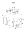
- Fig. 1 is a perspective view showing the embodiment in the case where a switching device according to the invention is applied to a direct current breaking relay.
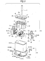
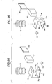
- Fig. 2 is an exploded perspective view of Fig. 1.
- Fig. 3 is an exploded perspective view of the relay main body shown in Fig. 2.
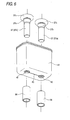
- Fig. 4 is an exploded perspective view of the electromagnetic block shown in Fig. 3.
- Fig. 5 is a partly broken perspective view of a sealing case shown in Fig. 4.
- Fig. 6 is an exploded perspective view of the sealing case shown in Fig. 4.
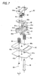
- Fig. 7 is an exploded perspective view of a movable contact block shown in Fig. 3.
- Fig. 8 is an exploded perspective view of a fixed contact block shown in Fig. 3.
- Figs. 9A and 9B are exploded perspective views of an important portion of the fixed contact block shown in Fig. 8.
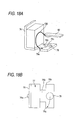
- Fig. 10A is a perspective view of the insulation case shown in Fig. 3 and Fig. 10B is a variation example of the insulation case.
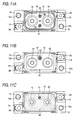
- Figs. 11A, 11B, and 11C are plan views showing the sealing process.
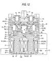
- Fig. 12 is a vertical cross sectional front view of the direct current breaking relay shown in Fig. 1.
- Fig. 13 is a partly enlarged cross sectional view of Fig. 12.
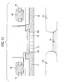
- Fig. 14 is an enlarged cross sectional view of an important portion of the direct current breaking relay shown in Fig. 12.
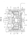
- Fig. 15 is a vertical cross secti onal lateral side view of the direct current breaking relay shown in Fig. 1.
- Fig. 16A is a partial perspective view showing the operation principle of the sealing case shown in Fig. 5 and Fig. 16B is a partial perspective view showing the operation principle of the sealing case according to the conventional example.
- Figs. 17A, 17B, and 17C are partial perspective views showing the movement of the generation source of the arc current according to the embodiment.
- Fig. 18A is a partial perspective view show ing the movement of the generation source of the arc current, continued from Fig. 17C and Fig. 18B is a plan view showing the movement of the generation source of the arc current.
- Fig. 19 is a perspective view showing the supporting structure of the contact piece according to a conventional example.
- Fig. 20 is a perspective view showing the supporting structure of the contact piece according to another conventional example.
-
- A preferred embodiment of the invention will be described according to the accompanying drawings of Fig. 1 to Fig. 18.
- This description will be made in the case where this embodiment is used for a relay for switching a direct current load, and as illustrated in Fig. 1 and Fig. 2, the main body of a
relay 20 is housed in a space integrally formed by abox case 10 and abox cover 15. - The
box case 10 has arecessed portion 11 capable of housing anelectromagnetic block 30 described later, and it is provided with throughholes 12 for fixing respectively at two corners positioned on one of the diagonal lines and withjointing concaves 13 at the remaining two corners, as illustrated in Fig. 2. A reinforcingcylinder 12a is inserted into each of the throughholes 12 and ajoint nut 13a is inserted into each of the jointing concaves 13. - The
box cover 15 can be fixed to thebox case 10 and it has a shape capable of housing a sealingcase block 40 described later. Thebox cover 15 is provided withcontact holes contact terminals main body 20 described later protrude respectively as well as with protrudingportions gas discharge pipe 21, on its ceiling surface. Apartition wall 18 connects the both protrudingportions engagement hole 19 provided on the lower end portion of thebox cover 15 is engaged with eachengagement claw 14 provided on the upper end portion of thebox case 10, hence to combine the both integrally. - The relay
main body 20 is constituted by sealing acontact mechanism block 50 within thesealing case block 40 mounted on theelectromagnetic block 30, as illustrated in Fig. 2 and Fig. 3. - As illustrated in Fig. 4, the
electromagnetic block 30 includes a pair ofspools coil 31 wound around, combined with twoiron cores shaped yoke 39. - In the
spool 32,relay terminals lower collar portion 32a, ofcollar portions coil 31 wound around thespool 32 is entwined with one end (entwined portion) 34a of onerelay terminal 34 and soldered there and the other end is entwined with the other end (entwined portion) 35a of theother relay terminal 35 and soldered there. In therelay terminals portion 34a is curved and the other end (joint portion) 35b is also curved. Of therelay terminals spools joint portion 35b of oneadjacent relay terminal 35 is jointed to the entwinedportion 34a of the otheradjacent relay terminal 34 and soldered there. Further, the entwinedportion 35a of oneadjacent relay terminal 35 is jointed to thejoint portion 34b of theother relay terminal 34 and soldered there, hence to connect the twocoils coil terminals lower collar portions spools 32 and respectively connected to thejoint portions relay terminals 34 and 35 (Fig. 3). - The sealing
case block 40 is formed by a sealingcase 41 capable of housing thecontact mechanism block 50 described later and a sealingcover 45 for sealing the opening portion of the sealingcase 41. A pair offitting holes iron cores 37 is formed on the bottom surface of the sealing case 41 (Fig. 6). A slit 43 for connecting the both holes is provided between thefitting holes cover 45, as illustrated in Fig. 3, a pair of throughholes contact terminals contact mechanism block 50 described later and aloose hole 47 for loosely fitting thegas discharge pipe 21 are provided on the bottom surface of the concave 45a. - Assembling the
electromagnetic block 30 and the sealingcase block 40 is performed in the following procedure. - At first, the
relay terminals collar portion 32a that is placed at one side of thespools 32, thecoil 31 is wound around thespools 32, each drawing line is entwined with each of the entwinedportions relay terminals spools 32 is aligned with the entwinedportions joint portions relay terminals portion 35a of therelay terminal 35 is jointed to thejoint portion 34b of the otheradjacent relay terminal 34 and soldered. Thejoint portion 35b of therelay terminal 35 is jointed to the entwinedportion 34a of the otheradjacent relay terminal 34 and soldered there, hence to connect thecoils - As illustrated in Fig. 6, the
respective iron cores 37 are inserted into the respective fitting holes 42 provided on the bottom surface of the sealingcase 41 andpipes 38 are respectively attached to theshafts 37a of the protrudingiron cores 37. Each of thepipes 38 is pushed to each of theiron cores 37 from the opening edge of thepipe 38 in a direction of the shaft. In theiron core 37, the diameter of theshaft portion 37a is smaller than the diameter of thefitting hole 42 of the sealingcase 41 and smaller than the inner diameter of thepipe 38. The diameter of abottleneck portion 37b of theiron core 37 is larger than the diameter of thefitting hole 42 of the sealingcase 41 and larger than the inner diameter of thepipe 38. Therefore, when theiron core 37 is pushed down in a direction of the shaft, thebottleneck portion 37b of theiron core 37 goes through thefitting hole 42 of the sealingcase 41 expanding it and further goes through thepipe 38 expanding the inner diameter of thepipe 38. The opening end portion of thepipe 38 and the head portion (magnetic pole portion) 37c of theiron core 37 are fixedly fitted to the opening portion of thefitting hole 42 upwardly and downwardly. The opening portion of thefitting hole 42 of the sealingcase 41 is caulked in three directions. - According to the embodiment, since the sealing
case 4 1 is made from material having the thermal expansion coefficient higher than theiron core 37 and thepipe 38, for example, aluminum, it is effective in securing airtightness even when a temperature changes. - Even when each component expands with an increa se in temperature, since the expansion of the sealing
case 41 in a thickness direction is relatively larger than that of the other components, the sealingcase 41 can be more strongly supported by thehead portions 37c of theiron cores 37 and thepipes 38. While, when each component shrinks with a decrease in temperature, since the shrinkage of thefitting hole 42 of the sealingcase 41 in a diameter direction is relatively larger than that of the other components, thebottleneck portion 37b of theiron core 37 is choked. In order to retrain generation of thermal stress while securing the airtightness, it is preferable that the thermal expansion coefficient of theiron core 37 is substantially equal to that of thepipe 38. - When the sealing
case 41 is mad e from aluminum that can be easily processed, a sealing work becomes easy and hydrogen becomes difficult to penetrate the case advantageously. - According to the embodiment, since the
slit 43 is provided in the bottom surface of the sealingcase 41, even when a change of magnetic flux occurs in theiron core 37, eddy currents can be prevented by this slit, as illustrated in Fig. 16. Therefore, by preventing generation of the magnetic flux caused by the above eddy currents, the return operation of amovable iron piece 66 described later can be smoothly performed. This can restrain the deterioration of the blocking performance caused by a delay of the return operation. - A method for preventing the generation of the eddy currents is not restricted to the above method of providing the
slit 43 of connecting the fitting holes 42 and 42 but also, for example, at least one cut-off portion individually formed around each of the fitting holes 42 and 42 may be provided. Generation of the eddy currents may be restrained by forming a rough uneven surface around the fitting holes 42 of the bottom surface of the sealingcase 41 to increase the electric resistance. - As illustrated in Fig. 4, the
respective iron cores 37 and therespective pipes 38 are inserted into respective center holes 32c of thespools 32, so that the respective distal ends of the protrudingiron cores 37 go throughrespective caulking holes 39a of theyoke 39, hence to fix the above components firmly. Thus, theelectromagnetic block 30 with the sealingcase 41 mounted there is completed. An insulatingsheet 39b in order to enhance the insulation performance is arranged between theyoke 39 and thecollar portion 32a of thespools 32. - The
coil terminals 36 are respectively hung over the upper andlower collar portions spools 32. The lower ends of thecoil terminals 36 are respectively connected to thejoints portions relay terminals electromagnetic block 30 and the sealingcase 41 is completed. The sealingmaterial 98 is injected into the bottom of the sealingcase 41 and hardened there, to seal theslit 43. The sealingmaterial 98 is made, for example, by adding alumina powder to an epoxy resin and when it is hardened, it has the almost same line expansion rate as aluminum. - The
contact mechanism block 50 comprises amovable contact block 60, fixed contact blocks 70 and 80 mounted on the both sides of theblock 60, and aninsulation case 90 for housing and unitizing these blocks, as illustrated in Fig. 3. - In the
movable contact block 60, amovable contact piece 62 and a pair ofcoil springs movable insulation base 61 with astopper 64, as illustrated in Fig. 7. A pair of return coil springs 65 and 65, amovable iron piece 66, and a shieldingplate 67 are firmly staked to themovable insulation base 61 with a pair ofrivets - In the
movable insulation base 61,deep grooves guide protrusion 61a protruding in the center of the base on its upper surface so as to accommodate the coil springs 63 without dropping them. On the bottom surface of themovable insulation base 61, aleg portion 61c having a substantially-cross shaped section is formed in its center andconcave portions concave portion 61d is not illustrated) for positioning the return coil springs 65 are formed on its both sides. - The
movable contact piece 62 is designed in that the both ends of band-shaped thick conductive material become semicircle and a guide long hollow 62a is provided in its center. The coil springs 63 are to add a contact pressure to themovable contact piece 62 and to always urge themovable contact piece 62 downward. - In assembling the
movable contact block 60, at first, the guide long hollow 62a of themovable contact piece 62 is fitted to theguide protrusion 61a of themovable insulation base 61. Then, a pair of the coil springs 63 and 63 are fitted to thedeep grooves stopper 64 is attached there. Therivets concave portions movable insulation base 61, passing throughcaulking holes 66a of themovable iron piece 66 andcaulking holes 67a of the shieldingplate 67. Then, therivets caulking holes movable insulation base 61 andcaulking holes 64a of thestopper 64, thereby staking the above components and completing the assembly work. According to the embodiment, themovable contact piece 62 is always urged downward by, the spring force of the coil springs 63 so as not to allow a wobble. - As illustrated in Fig. 8 and Fig. 9, the fixed contact blocks 70 and 80 have the same shape and the same structure. They are formed by attaching the fixed
contact terminals contact terminals permanent magnets contact bases - The fixed
contact bases protruding portions bases portions engagement projections engagement holes 71b and 81b that can be mutually engaged with each other are formed on the surface of the both edges. Further, in the protrudingportions grooves grooves grooves - As illustrated in Fig. 8 and Fig. 9, the fixed
contact terminals contact portions permanent magnets contact terminals positioning projections projections insulation case 90 described later (Fig. 13), hence to regulate the position of the fixedcontact terminals contacts contact terminals narrow portions fixed contact portions permanent magnets angles permanent magnets permanent magnets - The
insulation case 90 is to unitize the contact mechanism block 50, as illustrated in Fig. 3. Theinsulation case 90 is provided with a pair of the gas discharge holes 92 and 92 on the both sides symmetric with respect to a central line connecting the terminal holes 91 and 91 which are provided on the top surface of the case (Fig. 3 and Fig. 10A). It is in order to make the orientation indifferent in the assembly mode that a pair of the gas discharge holes 92 is provided symmetrically. Eachcircular protrusion 93 for preventing the intrusion of the sealing material may be integrated with each of the opening ends of the gas discharge holes 92 (Fig. 10B). - The procedure of assembling the
contact mechanism block 50 will be described below. - While pulling up each lower end of the return springs 65 of the assembled
movable contact block 60, the fixed contact blocks 70 and 80 are attached to themovable insulation base 61 on its both sides, and theengagement projections 71a of the respectivematching protruding portions matching protruding portions matching protruding portions engagement projections 81a of the respectivematching protruding portions contact bases insulation case 90 to the fixed contact blocks 70 and 80, thecontact terminals contact mechanism block 50. Here, the gas discharge holes 92 and 92 communicate with the operation holes 51 and 52 since they are positioned on the same axis (Fig. 15). - When the
contact mechanism block 50 is inserted into the sealingcase 41 containing the electromagnetic block 30 (Fig. 12), theleg portions contact bases head portions 37c that are the magnetic pole portions of theiron cores 37, and themovable iron piece 66 faces themagnetic pole portions 37c through the shieldingplate 67 in a removable way. A pair of measurement probes (not illustrated) are respectively inserted into the operation holes 51 and 52 provided between the respective gas discharge holes 92 and 92 of theinsulation case 90 and the respective fixedcontact bases rivets stopper 64 are pushed or released, in order to move themovable contact block 60 up and down and measure the operation characteristics of the contact pressure and the contact gap. As a result, when the operation characteristic is out of the tolerance level, fine adjustment is performed, while when the operation characteristic is within the tolerance level, the sealingcover 45 is attached to the sealingcase 41 and they are welded together (Fig. 11B). Agas discharge pipe 21 is pushed into one of the gas discharge holes 92 of theinsulation case 90 from theloose hole 47. Thesame sealing material 99 as the sealingmaterial 98 made from epoxy resin is injected into the sealingcover 45 and hardened there, so as to seal the basement around thecontact terminals case 41 is taken out through thegas discharge pipe 21 and a predetermined mixed gas is injected instead, and then thegas discharge pipe 21 is caulked and sealed. At last, thecoil terminals 36 are hung on a pair of thecollar portions spools 32, hence to complete the relay main body 20 (Fig. 2). - According to the embodiment, one of the gas discharge holes 92 is sealed by the
gas discharge pipe 21 and the other is covered with the sealingcover 45. Owing to this structure, even when the sealingmaterial 99 is injected, the sealingmaterial 99 will not intrude into theinsulation case 90. Since theloose hole 47 for inserting thepipe 21 is positioned at the position equally distant from therespective contact terminals - A liquid
elastic material 97 made from urethane resin is injected in the bottom surface of the recessedportion 11 of thecase 10, and the relaymain body 20 is accommodated in the recessedportion 11. Thecoil terminals 36 are positioned at thejointing concaves 13, and the liquidelastic material 97 is hardened there as it is with the relaymain body 20 hung within thecase 10. Thecover 15 is attached to thecase 10, hence to complete the direct current breaking relay. In the embodiment, although the liquidelastic material 97 filled and hardened is noise absorbing elastic material, it is not restricted to this but an elastic sheet may be used as a noise absorbing elastic material. Thecollar portions 32b of thespools 32 may be extended and hung within the recessedportion 11 of thecase 10. - The operation of the relay having the above structure will be described, this time.
- When no voltage is applied to the
coils 31 of theelectromagnetic block 30 , themovable insulation base 61 is pulled up by the spring force of the return springs 65 and 65 (Fig. 12). Therefore, themovable iron piece 66 is separated from themagnetic pole portions 37c of theiron cores 37 and the both ends of themovable contact piece 62 are separated from the fixedcontacts - When a voltage is applied to the
coils 31, themagnetic pole portions 37c of theiron cores 37 absorb themovable iron piece 66, and themovable iron piece 66 moves down against the spring force of the return springs 65. Thus, themovable insulation base 61 integrated with themovable iron piece 66 moves down, and after the both ends of themovable contact piece 62 come into contact with the fixedcontacts movable iron piece 66 is absorbed by themagnetic pole portions 37c of theiron cores 37. - According to the embodiment, since the shock when the
movable iron piece 66 comes into contact with themagnetic pole portions 37c of theiron cores 37 is absorbed and reduced by the hardened liquidelastic material 97 and thecoil terminals 36, collision sound can be restrained, hence to obtain a silent electromagnetic relay advantageously. - When the voltage applied to the
coils 31 is stopped, themovable insulation base 61 is raised by the spring force of the return springs 65, themovable iron piece 66 moving together with this is accordingly separated from themagnetic pole portions 37c of theiron cores 37, and the both ends of themovable contact piece 62 are separated from the fixedcontacts - According to the embodiment, when the both ends of the
movable contact piece 62 contact with and separate from the fixedcontacts contact bases grooves contact bases - When the both ends of the
movable contact piece 62 are separated from the fixedcontacts contact 78 and the generation source of the arc current 100 moves, it will never reach the permanent magnetic 77, which will not damage the permanent magnetic 77 advantageously. - More specifically, as illustrated in Fig. 17, even when the arc current 100 is generated in the fixed contact 78 (Fig. 17B) and the generation source of the arc current 100 is attracted by the magnetic force of the
permanent magnet 78 and moves (Fig. 17C, Fig. 18A, Fig. 18B), it will never arrive at thepermanent magnet 78. This is because the generation source of the arc current 100 has the characteristic of moving to a corner or an angle of the conductive material. According to the embodiment, thenarrow portion 76b is provided between the fixedcontact 78 and thepermanent magnet 77, hence to form theangle 76c in front of thepermanent magnet 77. Therefore, the generation source of the arc current 100 cannot move to thepermanent magnet 77 but move to theangle 76c. - In the embodiment, although the case of breaking the direct current has been described, the invention is not restricted to this case but it may be applied to the case of breaking an alternative current.
- The invention is not restricted to the above-mentioned electromagnetic relay, but it is needless to say that it may be applied to the supporting structure of fixed contact terminals concerned with a switch and a timer.
Claims (3)
- A supporting structure of fixed contact terminals in which basements of a pair of fixed contact terminals with respective fixed contacts provided on their free ends are supported by supporting bases and the both ends of a movable contact piece contact with and separate from the pair of the fixed contacts, comprising
insulation grooves each having a downwardly-broaden cross section which are formed on the surfaces of the supporting bases at each position near the fixed contacts so as to partition the basement of the pair of the fixed contact terminals. - The supporting structure of the fixed contact terminals according to Claim 1, in which
the insulation grooves have a converted T-shaped cross section. - The supporting structure of the fixed contact terminals according to Claim 1, in which
the insulation grooves have a substantially L-shaped cross section.
Applications Claiming Priority (2)
| Application Number | Priority Date | Filing Date | Title |
|---|---|---|---|
| JP2003424947 | 2003-12-22 | ||
| JP2003424947A JP4375012B2 (en) | 2003-12-22 | 2003-12-22 | Support structure for fixed contact terminals |
Publications (3)
| Publication Number | Publication Date |
|---|---|
| EP1548771A2 true EP1548771A2 (en) | 2005-06-29 |
| EP1548771A3 EP1548771A3 (en) | 2008-02-13 |
| EP1548771B1 EP1548771B1 (en) | 2012-10-03 |
Family
ID=34544936
Family Applications (1)
| Application Number | Title | Priority Date | Filing Date |
|---|---|---|---|
| EP04028951A Expired - Fee Related EP1548771B1 (en) | 2003-12-22 | 2004-12-07 | Supporting structure of fixed contact terminals |
Country Status (4)
| Country | Link |
|---|---|
| US (1) | US7286031B2 (en) |
| EP (1) | EP1548771B1 (en) |
| JP (1) | JP4375012B2 (en) |
| CN (1) | CN100351972C (en) |
Cited By (1)
| Publication number | Priority date | Publication date | Assignee | Title |
|---|---|---|---|---|
| EP3985705A1 (en) * | 2020-10-14 | 2022-04-20 | Gigavac, LLC | Switching device with improved epoxy hermetic seal |
Families Citing this family (16)
| Publication number | Priority date | Publication date | Assignee | Title |
|---|---|---|---|---|
| JP2011108452A (en) * | 2009-11-16 | 2011-06-02 | Fujitsu Component Ltd | Electromagnetic relay |
| JP5360291B2 (en) | 2010-03-15 | 2013-12-04 | オムロン株式会社 | Contact switchgear |
| JP5711044B2 (en) | 2010-12-02 | 2015-04-30 | 富士電機株式会社 | Magnetic contactor, gas sealing method of magnetic contactor, and method of manufacturing magnetic contactor |
| JP5689741B2 (en) * | 2011-05-19 | 2015-03-25 | 富士電機株式会社 | Magnetic contactor |
| JP5864902B2 (en) * | 2011-05-19 | 2016-02-17 | 富士電機機器制御株式会社 | Assembling method of arc extinguishing chamber of magnetic contactor |
| JP5727862B2 (en) | 2011-05-19 | 2015-06-03 | 富士電機機器制御株式会社 | Magnetic contactor |
| JP5778989B2 (en) * | 2011-05-19 | 2015-09-16 | 富士電機機器制御株式会社 | Magnetic contactor |
| JP5684649B2 (en) * | 2011-05-19 | 2015-03-18 | 富士電機機器制御株式会社 | Magnetic contactor |
| JP5856426B2 (en) * | 2011-10-07 | 2016-02-09 | 富士電機株式会社 | Contact device and electromagnetic contactor using the same |
| JP5876270B2 (en) * | 2011-11-01 | 2016-03-02 | 富士電機株式会社 | Magnetic contactor |
| USD713359S1 (en) * | 2012-10-29 | 2014-09-16 | Dynapar Corporation | Electrical contactor |
| JP6175764B2 (en) * | 2012-12-12 | 2017-08-09 | 富士電機機器制御株式会社 | Magnetic contactor |
| US20140285973A1 (en) * | 2013-03-21 | 2014-09-25 | Samsung Electro-Mechanics Co., Ltd. | Housing and power module having the same |
| CN105359243B (en) | 2013-06-28 | 2018-06-05 | 松下知识产权经营株式会社 | Contact making device and the electromagnetic relay for being equipped with the contact making device |
| JP7206831B2 (en) * | 2018-11-16 | 2023-01-18 | オムロン株式会社 | Contact device |
| JP7052687B2 (en) * | 2018-11-16 | 2022-04-12 | オムロン株式会社 | Contact device |
Citations (1)
| Publication number | Priority date | Publication date | Assignee | Title |
|---|---|---|---|---|
| DE3823315A1 (en) | 1988-07-09 | 1990-01-11 | Zettler Elektrotechn Alois | Insulating body between the live contacts of a contact spring set for electromagnetic relays |
Family Cites Families (11)
| Publication number | Priority date | Publication date | Assignee | Title |
|---|---|---|---|---|
| DE893829C (en) * | 1951-08-25 | 1953-10-19 | Siemens Ag | Insulating body preferably made of molded material for the contact fastening of switches, in particular cam switches |
| US4199740A (en) * | 1978-04-24 | 1980-04-22 | General Electric Company | Switch device and method of making |
| JPH0723871Y2 (en) * | 1987-07-24 | 1995-05-31 | 富士電機株式会社 | Electromagnetic contactor |
| US5519370A (en) * | 1991-03-28 | 1996-05-21 | Kilovac Corporation | Sealed relay device |
| JPH06290670A (en) * | 1993-03-30 | 1994-10-18 | Toshiba Lighting & Technol Corp | Switch and pushbutton switch |
| JP3166559B2 (en) * | 1994-10-25 | 2001-05-14 | 富士電機株式会社 | Electromagnetic device of electromagnetic contactor |
| JPH08329814A (en) * | 1995-05-31 | 1996-12-13 | Matsushita Electric Works Ltd | Electromagnetic relay |
| DE19537612C1 (en) * | 1995-10-09 | 1997-01-09 | Siemens Ag | Electromagnetic relay and process for its manufacture |
| DE19653637C2 (en) * | 1996-12-20 | 2001-02-01 | Siegfried Baer | Electrical switch |
| US6765463B2 (en) * | 2001-06-22 | 2004-07-20 | Tyco Electronics Austria, GmbH | Relay |
| JP4471859B2 (en) * | 2005-01-31 | 2010-06-02 | 富士通コンポーネント株式会社 | Electromagnetic relay |
-
2003
- 2003-12-22 JP JP2003424947A patent/JP4375012B2/en not_active Expired - Fee Related
-
2004
- 2004-12-07 EP EP04028951A patent/EP1548771B1/en not_active Expired - Fee Related
- 2004-12-16 US US11/014,637 patent/US7286031B2/en active Active
- 2004-12-21 CN CNB2004100819014A patent/CN100351972C/en not_active Expired - Fee Related
Patent Citations (1)
| Publication number | Priority date | Publication date | Assignee | Title |
|---|---|---|---|---|
| DE3823315A1 (en) | 1988-07-09 | 1990-01-11 | Zettler Elektrotechn Alois | Insulating body between the live contacts of a contact spring set for electromagnetic relays |
Cited By (2)
| Publication number | Priority date | Publication date | Assignee | Title |
|---|---|---|---|---|
| EP3985705A1 (en) * | 2020-10-14 | 2022-04-20 | Gigavac, LLC | Switching device with improved epoxy hermetic seal |
| US11621131B2 (en) | 2020-10-14 | 2023-04-04 | Gigavac, Llc | Switching device with improved epoxy hermetic seal |
Also Published As
| Publication number | Publication date |
|---|---|
| CN1637992A (en) | 2005-07-13 |
| EP1548771A3 (en) | 2008-02-13 |
| EP1548771B1 (en) | 2012-10-03 |
| CN100351972C (en) | 2007-11-28 |
| JP2005183277A (en) | 2005-07-07 |
| US7286031B2 (en) | 2007-10-23 |
| JP4375012B2 (en) | 2009-12-02 |
| US20050148216A1 (en) | 2005-07-07 |
Similar Documents
| Publication | Publication Date | Title |
|---|---|---|
| EP1548782B1 (en) | Switching device | |
| EP1548771B1 (en) | Supporting structure of fixed contact terminals | |
| US9640355B2 (en) | Contact apparatus | |
| EP2141723B1 (en) | Electromagnet device | |
| EP1548774A2 (en) | Switching device | |
| EP2141724B1 (en) | Contact device | |
| JP5966469B2 (en) | Sealed contact device | |
| US6486760B2 (en) | Electromagnetic relay | |
| EP3139396B1 (en) | Contact switching device | |
| JP3985628B2 (en) | Switchgear | |
| JP4321256B2 (en) | Electromagnetic relay | |
| JP2004071512A (en) | Switching device | |
| WO2007132773A1 (en) | Electromagnetic relay | |
| US6608539B2 (en) | Electromagnet driving apparatus and electromagnetic relay | |
| US5243312A (en) | Electromagnetic relay | |
| EP3979289A1 (en) | Direct current relay and manufacturing method therefor | |
| JP4273957B2 (en) | Electromagnetic relay | |
| JPH0330971Y2 (en) | ||
| JP7363619B2 (en) | electromagnetic contactor | |
| JPH09204867A (en) | Polarized relay | |
| JP2000100301A (en) | Signal switching device |
Legal Events
| Date | Code | Title | Description |
|---|---|---|---|
| PUAI | Public reference made under article 153(3) epc to a published international application that has entered the european phase |
Free format text: ORIGINAL CODE: 0009012 |
|
| AK | Designated contracting states |
Kind code of ref document: A2 Designated state(s): AT BE BG CH CY CZ DE DK EE ES FI FR GB GR HU IE IS IT LI LT LU MC NL PL PT RO SE SI SK TR |
|
| AX | Request for extension of the european patent |
Extension state: AL BA HR LV MK YU |
|
| PUAL | Search report despatched |
Free format text: ORIGINAL CODE: 0009013 |
|
| AK | Designated contracting states |
Kind code of ref document: A3 Designated state(s): AT BE BG CH CY CZ DE DK EE ES FI FR GB GR HU IE IS IT LI LT LU MC NL PL PT RO SE SI SK TR |
|
| AX | Request for extension of the european patent |
Extension state: AL BA HR LV MK YU |
|
| 17P | Request for examination filed |
Effective date: 20080530 |
|
| AKX | Designation fees paid |
Designated state(s): DE ES FR GB IT |
|
| 17Q | First examination report despatched |
Effective date: 20101228 |
|
| REG | Reference to a national code |
Ref country code: DE Ref legal event code: R079 Ref document number: 602004039512 Country of ref document: DE Free format text: PREVIOUS MAIN CLASS: H01H0009020000 Ipc: H01H0009480000 |
|
| RIC1 | Information provided on ipc code assigned before grant |
Ipc: H01H 9/02 20060101ALI20120217BHEP Ipc: H01H 9/48 20060101AFI20120217BHEP |
|
| GRAP | Despatch of communication of intention to grant a patent |
Free format text: ORIGINAL CODE: EPIDOSNIGR1 |
|
| GRAS | Grant fee paid |
Free format text: ORIGINAL CODE: EPIDOSNIGR3 |
|
| GRAA | (expected) grant |
Free format text: ORIGINAL CODE: 0009210 |
|
| RIN1 | Information on inventor provided before grant (corrected) |
Inventor name: NISHIDA, TAKESHI OMRON CORPORATION Inventor name: MASUI, YASUYUKI OMRON CORPORATION Inventor name: MIYASAKA, TAKESHI OMRON CORPORATION |
|
| AK | Designated contracting states |
Kind code of ref document: B1 Designated state(s): DE ES FR GB IT |
|
| REG | Reference to a national code |
Ref country code: GB Ref legal event code: FG4D |
|
| REG | Reference to a national code |
Ref country code: DE Ref legal event code: R096 Ref document number: 602004039512 Country of ref document: DE Effective date: 20121129 |
|
| REG | Reference to a national code |
Ref country code: DE Ref legal event code: R082 Ref document number: 602004039512 Country of ref document: DE Representative=s name: KILIAN KILIAN & PARTNER, DE Ref country code: DE Ref legal event code: R082 Ref document number: 602004039512 Country of ref document: DE Representative=s name: KILIAN KILIAN & PARTNER MBB PATENTANWAELTE, DE |
|
| PG25 | Lapsed in a contracting state [announced via postgrant information from national office to epo] |
Ref country code: ES Free format text: LAPSE BECAUSE OF FAILURE TO SUBMIT A TRANSLATION OF THE DESCRIPTION OR TO PAY THE FEE WITHIN THE PRESCRIBED TIME-LIMIT Effective date: 20130114 |
|
| PLBE | No opposition filed within time limit |
Free format text: ORIGINAL CODE: 0009261 |
|
| STAA | Information on the status of an ep patent application or granted ep patent |
Free format text: STATUS: NO OPPOSITION FILED WITHIN TIME LIMIT |
|
| 26N | No opposition filed |
Effective date: 20130704 |
|
| GBPC | Gb: european patent ceased through non-payment of renewal fee |
Effective date: 20130103 |
|
| REG | Reference to a national code |
Ref country code: DE Ref legal event code: R097 Ref document number: 602004039512 Country of ref document: DE Effective date: 20130704 |
|
| PG25 | Lapsed in a contracting state [announced via postgrant information from national office to epo] |
Ref country code: GB Free format text: LAPSE BECAUSE OF NON-PAYMENT OF DUE FEES Effective date: 20130103 |
|
| REG | Reference to a national code |
Ref country code: FR Ref legal event code: PLFP Year of fee payment: 12 |
|
| REG | Reference to a national code |
Ref country code: FR Ref legal event code: PLFP Year of fee payment: 13 |
|
| REG | Reference to a national code |
Ref country code: FR Ref legal event code: PLFP Year of fee payment: 14 |
|
| PGFP | Annual fee paid to national office [announced via postgrant information from national office to epo] |
Ref country code: DE Payment date: 20191126 Year of fee payment: 16 |
|
| PGFP | Annual fee paid to national office [announced via postgrant information from national office to epo] |
Ref country code: IT Payment date: 20191209 Year of fee payment: 16 Ref country code: FR Payment date: 20191115 Year of fee payment: 16 |
|
| REG | Reference to a national code |
Ref country code: DE Ref legal event code: R119 Ref document number: 602004039512 Country of ref document: DE |
|
| PG25 | Lapsed in a contracting state [announced via postgrant information from national office to epo] |
Ref country code: IT Free format text: LAPSE BECAUSE OF NON-PAYMENT OF DUE FEES Effective date: 20201207 Ref country code: FR Free format text: LAPSE BECAUSE OF NON-PAYMENT OF DUE FEES Effective date: 20201231 |
|
| PG25 | Lapsed in a contracting state [announced via postgrant information from national office to epo] |
Ref country code: DE Free format text: LAPSE BECAUSE OF NON-PAYMENT OF DUE FEES Effective date: 20210701 |