EP1548731A2 - Optical disk apparatus, method for controlling the same, and recording medium - Google Patents
Optical disk apparatus, method for controlling the same, and recording medium Download PDFInfo
- Publication number
- EP1548731A2 EP1548731A2 EP04029203A EP04029203A EP1548731A2 EP 1548731 A2 EP1548731 A2 EP 1548731A2 EP 04029203 A EP04029203 A EP 04029203A EP 04029203 A EP04029203 A EP 04029203A EP 1548731 A2 EP1548731 A2 EP 1548731A2
- Authority
- EP
- European Patent Office
- Prior art keywords
- optical disk
- layer
- medium
- double
- optical
- Prior art date
- Legal status (The legal status is an assumption and is not a legal conclusion. Google has not performed a legal analysis and makes no representation as to the accuracy of the status listed.)
- Granted
Links
Images


Classifications
-
- G—PHYSICS
- G11—INFORMATION STORAGE
- G11B—INFORMATION STORAGE BASED ON RELATIVE MOVEMENT BETWEEN RECORD CARRIER AND TRANSDUCER
- G11B19/00—Driving, starting, stopping record carriers not specifically of filamentary or web form, or of supports therefor; Control thereof; Control of operating function ; Driving both disc and head
- G11B19/02—Control of operating function, e.g. switching from recording to reproducing
- G11B19/12—Control of operating function, e.g. switching from recording to reproducing by sensing distinguishing features of or on records, e.g. diameter end mark
- G11B19/127—Control of operating function, e.g. switching from recording to reproducing by sensing distinguishing features of or on records, e.g. diameter end mark involving detection of the number of sides, e.g. single or double, or layers, e.g. for multiple recording or reproducing layers
-
- G—PHYSICS
- G11—INFORMATION STORAGE
- G11B—INFORMATION STORAGE BASED ON RELATIVE MOVEMENT BETWEEN RECORD CARRIER AND TRANSDUCER
- G11B7/00—Recording or reproducing by optical means, e.g. recording using a thermal beam of optical radiation by modifying optical properties or the physical structure, reproducing using an optical beam at lower power by sensing optical properties; Record carriers therefor
- G11B2007/0003—Recording, reproducing or erasing systems characterised by the structure or type of the carrier
- G11B2007/0006—Recording, reproducing or erasing systems characterised by the structure or type of the carrier adapted for scanning different types of carrier, e.g. CD & DVD
-
- G—PHYSICS
- G11—INFORMATION STORAGE
- G11B—INFORMATION STORAGE BASED ON RELATIVE MOVEMENT BETWEEN RECORD CARRIER AND TRANSDUCER
- G11B7/00—Recording or reproducing by optical means, e.g. recording using a thermal beam of optical radiation by modifying optical properties or the physical structure, reproducing using an optical beam at lower power by sensing optical properties; Record carriers therefor
- G11B7/007—Arrangement of the information on the record carrier, e.g. form of tracks, actual track shape, e.g. wobbled, or cross-section, e.g. v-shaped; Sequential information structures, e.g. sectoring or header formats within a track
- G11B7/00736—Auxiliary data, e.g. lead-in, lead-out, Power Calibration Area [PCA], Burst Cutting Area [BCA], control information
-
- G—PHYSICS
- G11—INFORMATION STORAGE
- G11B—INFORMATION STORAGE BASED ON RELATIVE MOVEMENT BETWEEN RECORD CARRIER AND TRANSDUCER
- G11B7/00—Recording or reproducing by optical means, e.g. recording using a thermal beam of optical radiation by modifying optical properties or the physical structure, reproducing using an optical beam at lower power by sensing optical properties; Record carriers therefor
- G11B7/24—Record carriers characterised by shape, structure or physical properties, or by the selection of the material
- G11B7/2403—Layers; Shape, structure or physical properties thereof
- G11B7/24035—Recording layers
- G11B7/24038—Multiple laminated recording layers
Definitions
- the present invention relates to an optical disk apparatus that records and reproduces information on and from an optical disk, as well as a method for controlling the optical disk apparatus, and in particular, to an optical disk apparatus that automatically determines a standard for the optical disk.
- Optical disks of this kind include, for example, a reproduction-only DVD-ROM (Digital Versatile Disk-Read Only Memory), a rewritable DVD-RAM (Random Access Memory), a DVD-RW (Rewritable), a +RW, and a recordable DVD-R (Recordable), which conform to various standards.
- DVD-ROM Digital Versatile Disk-Read Only Memory
- rewritable DVD-RAM Random Access Memory
- DVD-RW Rewritable
- +RW +RW
- recordable DVD-R Recordable
- An optical disk apparatus that can execute recording and reproduction on optical disks conforming to several types of standards comprises a function utilizing the fact that the light reflectance of the optical disk varies depending on the standard. This function automatically determines the standard for the optical disk installed to regulate each section of the optical disk apparatus and change settings on the basis of the result of the determination.
- rewritable optical disks there are two types of rewritable optical disks.
- One of them has a high light reflectance and records data after inverting (initializing) a characteristic of a recording film so that the film, which otherwise photoelectrically converts reflected light into an H (High) level, photoelectrically converts the reflected light into a L (Low) level (this type of optical disk will hereinafter be referred to as an L-H medium).
- the other has a low light reflectance and records data after inverting (initializing) the characteristic of the recording film so that the film, which otherwise photoelectrically converts the reflected light into the L level, photoelectrically converts the reflected light into the H level (this type of optical disk will hereinafter be referred to as an H-L medium).
- each of the rewritable optical disks conforming to the same standard is an L-H or H-L medium to regulate each section of the optical disk apparatus, and change settings.
- Jpn. Pat. Appln. KOKAI Publication No. 2001-266367 discloses a configuration that executes a focus search on an optical disk installed to measure the light reflectance of the optical disk on the basis of a focus error signal obtained.
- the configuration thus determines whether the disk is a CD (Compact Disk)-ROM, a CD-R, or a CD-RW to switch recording and reproducing circuits in accordance with the result of the determination.
- CD Compact Disk
- the present invention has been made in view of the above circumstances. It is an object of the present invention to provide an optical disk apparatus that automatically determine the type of rewritable optical disks conforming to the same standard, the type of which is based on a characteristic of a recording film, as well as a method for controlling the optical disk apparatus.
- an optical disk apparatus in which a first,. second, third, and fourth optical disks are selectively installed, the first and second optical disks having different recording film characteristics and both having a single-layer recording layer, the third and fourth optical disks having different recording film characteristics and both having a double-layer recording layer, the optical disk apparatus recording and reproducing information on and from the optical disk installed.
- the optical disk apparatus comprises an optical head which irradiates the optical disk installed with a light beam to provide a reproduction signal corresponding to reflected light and a determining section which uses the optical head to reproduce information from an innermost peripheral portion of the optical disk installed to determine which of the first to fourth optical disks has been installed, on the basis of the level of a reproduction signal obtained.
- the optical disk apparatus further comprises a reproduction signal processing section which processes the reproduction signal provided by the optical head to extract information from the reproduction signal, and a control section which controls the reproduction signal processing section on the basis of the result of the determination by the determining section.
- the control section controls the reproduction signal processing section on the basis of the result of the determination by the determining section to reproduce information indicating the type of the optical disk recorded in the inner peripheral portion of the optical disk installed.
- the control section then checks the information reproduced against the result of the determination by the determining section to determine which of the first to fourth optical disks has been installed.
- a recording medium according to the present invention serves as an optical disk applied to the above optical disk apparatus.
- the innermost peripheral portion of the recording medium has a BCA and includes a double-layer L-H medium and a double-layer H-L medium.
- the range of light reflectance of an L0 layer of the double-layer L-H medium in an initialized state does not overlap the range of light reflectance of an L0 layer of the double-layer H-L medium in an uninitialized state.
- the recording medium includes a single-layer L-H medium and a single-layer H-L medium.
- the light reflectances of the single-layer L-H medium in the initialized state, the L0 layer of the double-layer H-L medium in the initialized state, and the L0 layer of the double-layer L-H medium in the uninitialized state do not overlap the light reflectance of the single-layer H-L medium in the initialized state.
- the recording media according to the present invention are formed so that the light reflectances of the single-layer L-H medium in the initialized state, the L0 layer of the double-layer H-L medium in the initialized state, and the L0 layer of the double-layer L-H medium in the initialized state and uninitialized state are each set at 4 to 10%.
- the light reflectance of the single-layer H-L medium in the initialized state is set at 12 to 40%.
- the reflectance in the initialized state at a value larger than the minimum one at which an electric circuit can execute reproduction, it is possible to ensure that address information or the like is obtained during reproduction. Further, by setting both reflectances within the range in which a good reproduction signal is obtained, it is possible to produce an apparatus that can make determinations while retaining the high manufacturing quality of the medium.
- the first to fourth optical disks conforming to the same standard but having different recording film characteristics it is determined which of the first to fourth optical disks has been installed, on the basis of the level of a reproduction signal obtained by reproducing information from the innermost peripheral portion of the disk. This makes it possible to not only determine the basic standard for the optical disk but also automatically determine the type of the rewritable optical disks conforming to the same standard, the type of which is based on the characteristic of the recording film.
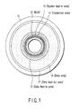
- FIG. 1 shows the structure of an information recording area in a single-layer rewritable optical disk 11.
- the following areas are formed in the optical disk from its inner periphery to its outer periphery: a BCA (Burst Cutting Area) 12, a system lead-in area 13, a connection area 14, a data lead-in area 15, a data area 16, and a data lead-out area 17.
- BCA Breast Cutting Area
- the data lead-in area 15, the data area 16, and the data lead-out area 17 employ a land groove system that uses concaves and convexes in the information recording layer to form an information recording track. Further, recorded information is read from the innermost peripheral BCA 12 to the outer periphery.
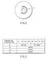
- Information is written in the BCA 12 of the optical disk 11 using a bar code as shown in FIG. 2.
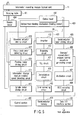
- the information written using the bar code includes the book version of standards and information on copyright protection as shown in FIG. 3.
- Two techniques are available for using a bar code to write information in the BCA 12.
- One of the techniques initializes a recoding film of the entire optical disk 11 and then removes the recording film and a reflecting film by laser trimming.
- the other utilizes a difference in light reflectance between an initialized state and uninitialized state of the recording film.
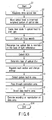
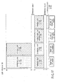
- FIG. 4 shows the data structure of the system lead-in area 13, connection area 14, and data lead-in area 15.
- Four zones including an initial zone 13a, a buffer zone 13b, a control data zone 13c, and a buffer zone 13d are constructed in the system lead-in area 13 in this order from inner periphery to outer periphery.
- connection area 14 is composed only of a connection zone 14a.
- Six zones including a guard track zone 15a, a disk test zone 15b, a drive test zone 15c, guard track zone 15d, a disk identification zone 15e, and DMA1 & DMA2 15f are formed in the data lead-in area 15 in this order from inner periphery to outer periphery.
- FIG. 5 is a block diagram showing the configuration of the information recording and reproducing apparatus.
- Reference numerals 401 and 402 denote an information recording medium (optical disk) and an optical head, respectively.
- Reference numeral 403 denotes a head feeding mechanism that controllably moves the optical head in a radial direction of the disk.
- a host apparatus (not shown) inputs record signal to an ECC encoding circuit 408 via a data I/O interface 422.
- the record signal is ECC-blocked and then supplied to a modulating circuit 407.
- the modulating circuit 407 then subjects the information to, for example, an 8/16 modulation.
- the information modulated is then input to a recording, reproduction, erasure, and control waveform generating circuit 406 to become a recording signal.
- the recording signal is supplied to a laser driving circuit 405 to control the intensity of a laser beam from the optical head 402.
- the optical head 402 reads a reproduction signal and an amplifier 413 amplifies the signal.
- the signal amplified is then input to a binarizing circuit 412, which binarizes the signal.
- the binarized signal is input to a PLL circuit 411 and a demodulating circuit 410.
- the demodulating circuit 410 carries out 16/8 demodulation.
- An error correcting circuit 409 then corrects errors in the signal demodulated for each ECC block.
- a semiconductor memory 419 is utilized.
- the amplifier 413, the binarizing circuit, the PLL circuit 411, and the demodulating circuit constitute a reproducing circuit (reproduction signal processing circuit) 430.
- the reproducing circuit 430 executes, for example, PRML (Partial Response and Maximum Likelihood) signal processing to execute information from a reproduction signal 30.
- PRML Partial Response and Maximum Likelihood
- the reproducing circuit 430 changes the gain of the amplifier 413 or processing parameters for the PRML signal processing for each area on the disk, that is, the BCA 12, the system lead-in area 13, or the like, on the basis of an instruction from a control section 420.
- the reproducing circuit 430 thus appropriately extracts information from the reproduction signal 30.
- a clock from the PLL circuit is input to a medium rotation speed detecting circuit 414.
- Rotation speed information detected by the medium rotation speed detecting circuit 414 is input to a spindle motor control section 415.
- the spindle motor control section 415 controls the rotation of a motor 404 to rotate a rotating table 421 so as to obtain the desired rotation speed of the optical disk 11.
- a feeding motor driving circuit 416 controls a feeding motor of the head feeding mechanism 403 and thus the relative positions of the optical head 402 and disk 401.
- a focus tracking error detecting circuit 417 detects a focus error, a tracking error, or the like in an optical head signal.
- the focus tracking error detecting circuit 417 provides an objective actuator driving mechanism 418 with a control signal for the error. This corrects the focus or tracking of the optical head 402.
- the control section 420 controls all the blocks and makes determination for the optical disk installed in the present apparatus. During recording, the control section 420, for example, generates management information recorded in the disk. During reproduction, the control section 420 recognizes, for example, a position from which management information is read and reproduced.
- the recording films are intended to, for example, improve the reliability of information recorded or reproduced, increase the number of times that information can be rewritten, or increase the recording speed.
- the optical disk 11 is an L-H or H-L medium, previously described, depends on the characteristics of the recording film used.
- the reproduction signal characteristic of the rewritable optical disk 11 is strictly defined. Accordingly, it is impossible to deal with the mixture of optical disks 11 with different types of recording films for the respective purposes or applications. In other words, the conventional optical disk apparatus cannot be adapted for the optical disk of an L-H medium as well as the optical disk 11 of an H-L medium in connection with recording or reproduction.
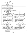
- FIG. 6 is a flowchart showing an operation performed by the optical disk apparatus 18 to automatically determine whether the optical disk 11 installed is an L-H or H-L medium to realize a recording or reproducing process adapted for the optical disk 11, that is, to enable the mixed use of the L-H and H-L media.
- the optical disk 11 is installed on the rotating table 421 to cause the apparatus to start operation (step S1).
- the control section 420 rotatively drives the optical disk.
- the control section 420 moves the optical head 402 to the innermost peripheral portion of the optical disk 11.
- the control section 420 causes a laser diode in the optical head 402 to emit light.
- step S5 the control section 420 carries out what is called a focus search; the control section 420 finds a surface reflection position of the optical disk 11 and moves an objective lens in the optical head 402 in a focus direction to search for a focused position of the lens.
- step S6 the control section 420 measures the light reflectance on the basis of the level of a reproduction signal. The control section 420 thus recognizes that the rewritable optical disk 11 has been installed.
- step S7 the control section 420 moves the optical head 402 in the radial direction of the optical disk 11 to detect the BCA 12.
- step S8 the control section 420 thus determines whether the optical disk is an L-H or H-L medium. Although described later in detail, this determination is made on the basis of a difference in reproduction signal level resulting from a difference in the reflectance of the recording film in the BCA 12 as well as the results of reading of bar code information (book version) recorded in the BCA 12.
- step S9 the control section 420 regulates each section of the apparatus and changes settings so as to adapt the apparatus for recording or reproduction executed on the optical disk 11 for which determination was made in step S8.
- step S10 the control section 420 carries out envelope detection to detect the system lead-in area 13.
- step S11 the control section 420 passes through the connection area 14.
- step S12 the control section 420 detects the data lead-in area 15.
- step S13 the control section 420 executes recording or reproduction on the data area 16. The control section 420 thus finishes the operation (step S14).
- the control section 420 determines whether the optical disk 11 is an L-H or H-L medium. Accordingly, in particular, the present invention has the advantage of reducing the time required to activate a circuit section that executes reproduction on the lead-in area.
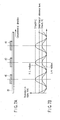
- FIG. 7A shows a disk in which after a formation of a recording film 40 and an initializing process has been executed to all over the surface of a disk substrate 39, bar code information is written by partly removing the recording film 40.
- the receding film 40 in an H-L. medium has a higher light reflectance than that in an L-H medium.
- the recoding film 40 in the H-L medium has a higher reproduction signal level than that in the L-H medium.
- FIG. 7B shows the reproduction signal levels of bar code information written in the BCAs 12 of optical disks of an L-H and H-L media.
- Parts of the optical disk free from the recording film have a light reflectance of almost 0%. Accordingly, the intensity of reflected light from these parts, that is, the minimum level of reproduction signals is almost zero.
- the maximum level Smax of a reproduction signal from a certain part of the recording film 40 corresponds to a light reflectance characteristic of the recording film 40. It is thus possible to accurately evaluate a difference in light reflectance between the L-H medium and the H-L medium.
- a determination reference level is set between the lower limit (the level of the lowest peak) of the maximum level Smax (H-L) of a reproduction signal from the H-L medium and the upper limit (the level of the highest peak) of the maximum level Smax (L-H) of a reproduction signal from the L-H medium.
- the maximum level Smax of the reproduction signal is compared with the determination reference level to determine the optical disk to be an L-H or H-L medium.
- the result of the determination is checked against the information on the book version of the standards read from the BCA 12. This further improves the reliability of the result of the determination.
- FIG. 8A an uninitialized recording film 42 is formed over the entire surface of a disk substrate 41. Bar code information is written in the recording film 42 by partly initializing the recording film 42.
- shaded parts denote the initialized parts.
- almost the entire recording film 42 in the BCA is uninitialized.
- the probability of reproduction signal from the BCA which is at a level obtained in the uninitialized state is much larger than that of reproduction signal from the BCA which is at a level obtained in the initialized state.
- the uninitialized part has a higher reflectance, and a reproduction signal from the uninitialized part is at the H level.
- the initialized part has a lower reflectance, and a reproduction signal from the initialized part is at the L level.
- the rate at which a reproduction signal at the H level is obtained is much higher than that at which a reproduction signal at the L level is obtained. This makes it possible to determine that the optical disk is an L-H medium.
- the uninitialized part has a lower reflectance, and a reproduction signal from the uninitialized part is at the L level.
- the initialized part has a higher reflectance, and a reproduction signal from the initialized part is at the H level.
- the rate at which a reproduction signal at the L level is obtained is much higher than that at which a reproduction signal at the H level is obtained. This makes it possible to determine that the optical disk is an H-L medium.
- the optical disk can be determined to be an L-H or H-L medium on the basis of the reproduction signal level as described above.
- the optical disk is determined to be an H-L disk when the rate at which a reproduction signal at the H level is obtained is higher than the rate at which a reproduction signal at the L level is obtained.
- the optical disk is determined to be an L-H disk when the rate at which a reproduction signal at the L level is obtained is higher than the rate at which a reproduction signal at the H level is obtained. In this manner, the result of the determination is opposite to that described above.
- the reliability of the determination result can also further be improved by checking the result of the determination against the information on the book version of the standards read from the BCA 12.
- FIG. 9 is a flowchart illustrating, in detail, an operation for making determination for the optical disk 11 as described above, particularly an operation performed in steps S7 to S9, shown in FIG. 6.
- step S15 an operation is started (step S15).
- step S16 the BCA 12 is detected.
- step S17 the control section 420 evaluates the reproduction signal level.
- step S18 the control section 420 determines whether the optical disk is an L-H or H-L medium.
- step S19 the control section 420 switches the gain of the amplifier 413 in the reproducing circuit 430, which processes a reproduction signal from the BCA 12, to a value compatible with the L-H medium.
- step S20 the control section 420 reads and reproduces the book version information, that is, the bar code information, from the BCA 12.
- step S21 the control section 420 checks the book version information against the result of the determination in step S18.
- step S22 the control section 420 determines whether or not they match.
- step S24 the control section 420 sets the signal processing section for recording and reproduction so that it is compatible with the L-H medium. The control section 420 then finishes the operation (step S24).
- the control section 420 switches the gain of the amplifier 413, which amplifies a reproduction signal from the BCA 12, to a value compatible with the H-L medium.
- step S26 the control section 420 reads and reproduces the book version information, that is, the bar code information, from the BCA 12.
- step S27 the control section 420 checks the book version information against the result of the determination in step S18.
- step S28 the control section 420 determines whether or not they match.
- step S24 the control section 420 sets the signal processing section for recording and reproduction so that it is compatible with the H-L medium. The control section 420 then finishes the operation (step S24).
- the light reflectance of the L-H medium in its initialized state is set 4 to 10%.
- the light reflectance of the H-L medium in its initialized state is set at 12 to 40%.
- a phase changing film used in the rewritable optical disk 11 similarly to conventional determining means based on the measurement of the light reflectance generally has a reflectance lower than 40%. Accordingly, the light reflectance at the L level is desirably as low as possible (as close to 0% as possible) so that the reproduction signal has a good contrast.
- reproduction signals obtained from all the areas are at the L level. Accordingly, since address information is reproduced, it is necessary to set the light reflectance at the L level to at least a reproducible level.
- the light reflectance be at least 5%. Circuit parts must be improved in order to detect a reproduction signal of a lower light reflectance than 5%. At present, it is thus difficult to realize an apparatus which can detect the lower light reflectance.
- the light reflectance of the L-H medium in the initialized state is desirably set to at most about 8%.
- the light reflectance of the L-H medium in the initialized state must be set at 4 to 10% as shown in FIG. 10, in order to manufacture a medium that provides good signal characteristics.
- the light reflectance in the initialized state (H level) must be set at about 15% in order to obtain good signal characteristics.
- the medium can be manufactured with a lower light reflectance.
- the light reflectance of the H-L medium at the H level must be higher than 10%, which corresponds to the upper limit light reflectance of the L-H medium at the L level. Accordingly, the light reflectance is defined to be at least 12% as shown in FIG. 10.
- the upper limit light reflectance of the H-L medium at the H level may be about 40% of the upper limit of the light reflectance of common phase changing materials. Accordingly, the upper limit light reflectance is defined as 40% as shown in FIG. 10. As described above, by specifying the light reflectance of the single-layer rewritable optical disk 11 in the initialized state, it is possible to accurately determine whether the optical disk is an H-L or L-H medium, while retaining a good reproduction signal quality.
- a layer (L0 layer) closer to a read-side surface and a layer (L1 layer) further from the read-side surface are present as recording surfaces.
- Information is reproduced and recorded by focusing laser light on one of the recording surfaces.
- the recording film characteristics are H-L and L-H.
- the apparent reflectance of the L1 layer (the ratio of the intensity of reflected light to the intensity of incident light observed at the optical head) is about one-fourth the actual reflectance (the ratio of the intensity of light reflected directly from the recording film to the intensity of light incident directly on the recording film) taking the reflection and absorption by the L0 layer into account.
- the phase changing film generally has a reflectance of at most about 40%.
- the L1 layer has an apparent reflectance of at most about 10%. Further, it is known in connection with problems with a detection circuit that the reflectance of the recording film must be at least about 5% in order to carry out detection of address information, tracking, and focusing on the recording film. Accordingly, the apparent reflectance of the L1 layer in the initialized state must be at least about 5%.
- the apparent reflectance of the L1 layer is at least about 5% in the initialized state (L level) and at most about 10% in the recording state (H level).
- the apparent reflectance in the initialized state (H level) is at most about 10%.
- the reflectance in the recording state (L level) can be set as close to 0% as possible in order to improve the SN ratio.
- the L0 layer must have a sufficient light transmittance to allow information to be read from the L1 layer. Accordingly, the reflectance of the L0 layer in the initialized state is preferably as low as possible.
- the reflectance of the L0 layer in the initialized state must be at least about 5% in order to carry out, for example, detection of the address section.
- an excessively high reflectance in the recording state (H level) increases inter-layer crosstalk. This affects reads from the L1 layer.
- the reflectance in the recording state (L level) can be set close to 0% in order to increase the SN ratio.
- a double-layer medium can be produced by using different recording films, for example, the L-H characteristic in a first layer and the H-L characteristic in a second layer.
- the reproducing circuit must be switched before accessing information recorded in the other layer, so that highspeed accesses from the L0 layer to the L1 layer are impossible. Consequently, this configuration is not practical. Accordingly, the embodiment of the present invention relates to a medium having two layers with the same recording film characteristic.
- the four types of media are mixed together using the determining method based on the evaluation of the intensity of a reproduction signal from the BCA area. as in the case of only the single-layer medium.
- This determining method can be roughly divided into two types in terms of a technique for writing bar code information in the BCA area.
- One of these methods writes a bar code in the BCA area by removing the recording film in the BCA area by laser trimming or the like.
- the other method records a bar code utilizing a difference in the reflectance of the recording film between the initialized state and the uninitialized state.
- the reflectance in the BCA area of the double-layer medium is evaluated by evaluating the intensity of a signal from the L0 layer as in the case of a reproduction-exclusive medium such as a DVD-ROM. This is because a signal from the L1 layer has passed through the L0 layer, an intermediate layer, and the like and is thus likely to be affected by environment, so that a signal from the L0 layer is more stable.
- the intensity of a reproduction signal corresponding to the reflectance of the recording film in the initialized state is first determined.
- a reference value for the reproduction signal intensity is preset on the basis of the difference between the lower limit reflectance of the single-layer H-L medium in the initialized state (H level) and the upper limit reflectance of the single-layer L-H medium in the initialized state (L level).
- the maximum value for the reflection signal intensity is larger than the reference value.
- the maximum value for the reflection signal intensity is smaller than the reference value. Consequently, medium determination is possible.
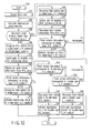
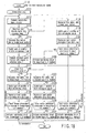
- FIG. 12 is a flowchart of medium determinations using a difference in reproduction signal intensity resulting from a difference in the reflectance of the recording film.
- a determining operation is started (step S30).
- the control section ,420 first detects the BCA area (step S31).
- the control section 420 thus detects the maximum value for the reproduction signal intensity (step S32).
- the control section 420 determines that the optical disk is a single-layer L-H medium or a double-layer L-H or H-L medium (step S34). On the basis of the result of the determination, the control section 420 adjusts, for example, the gain of the amplifier of the BCA reproducing circuit 430 (step S35). The control section 420 then accurately reproduces the book version information in the bar code information recorded in the BCA area (step S36). The control section 420 checks whether or not the book version information read corresponds to a single-layer L-H medium (step S37).
- the control section 420 determines that the optical disk is a single-layer L-H medium (step S38). The control section 420 then activates a reproducing circuit for a single-layer L-H medium, that is, sets, for example, the processing parameters of the reproducing circuit 430 for a single-layer L-H medium (step S39).
- the control section 420 checks whether or not the book version information corresponds to a double-layer H-L medium (step S40). If the book version information corresponds to a double-layer H-L medium (YES in step S40), the control section 420 determines that the optical disk is a double-layer H-L medium (step S41). The control section 420 then activates a reproducing circuit for a double-layer H-L medium, that is, sets, for example, the processing parameters of the reproducing circuit 430 for a double-layer H-L medium (step S42).
- the control section 420 checks whether or not the book version information corresponds to a double-layer L-H medium (step S43). If the book version information corresponds to a double-layer L-H medium (YES in step S43), the control section 420 determines that the optical disk is a double-layer L-H medium (step S44). The control section 420 then activates a reproducing circuit for a double-layer L-H medium, that is, sets, for example, the processing parameters of the reproducing circuit 430 for a double-layer L-H medium (step S45). If the book version information does not correspond to a double-layer L-H medium (NO in step S43), the flow returns to the evaluation of the reproduction signal intensity (step S32).
- step S32 if the maximum value of the reproduction signal intensity is larger than the reference value (YES in step S33), the control section 420 determines that the optical disk is a single-layer H-L medium (step S46). Then, the control section 420 adjusts the gain of the amplifier of the BCA reproducing circuit 430 (step S47). The control section 420 then reads and reproduces the book version information in the bar code information recorded in the BCA area (step S48). Then, the control section 420 checks whether or not the book version information read corresponds to a single-layer H-L medium (step S49).
- the control section 420 determines that the optical disk is a single-layer H-L medium (step S50). The control section 420 then activates a reproducing circuit for a single-layer H-L medium, that is, sets, for example, the processing parameters of the reproducing circuit 430 for a single-layer H-L medium (step S50). If the book version information does not match the result of evaluation of the reproduction signal intensity (NO in step S49, the flow returns to the evaluation of the reproduction signal intensity (step S32). During the above determining process, if a loop returning to the reevaluation of the reproduction signal intensity is entered many times, the control section 420 may output a medium determination error to allow the disk to be removed. Further, actually, not all these recording films need to be used, so that any steps of the determining method may be omitted.
- medium determinations can be made by providing a reference value (reference value 1) for a signal intensity level corresponding to a reflectance that is not included in both reflectance ranges of the single-layer H-L and L-H media.
- reference value 2 to compare the intensity of a signal from the double-layer L-H medium in the initialized state (L level) with that from the double-layer H-L medium in the uninitialized state (L level).
- the reproduction signal characteristic depends on a method for producing a bar code in the BCA area, that is, whether the bars of the bar code are initialized or uninitialized. Possible problems can be prevented by predetermining whether the bars of the bar code are initialized or uninitialized.
- the double-layer H-L medium has a reflectance lower than a detection sensitivity. Accordingly, when the bar code portion is initialized while the other portions are uninitialized, almost the entire BCA has such a low reflectance that detection is impossible.
- the double-layer H-L medium it is necessary to produce the bar code except for the bars in the initialized state, which provides a high reflectance, and the bar portions in the uninitialized state, which provides a low reflectance. Consequently, for the double-layer H-L medium, the bars in the bar code information recorded in the BCA area must be written in the uninitialized state. Therefore, the reproduction signal characteristic is uniquely determined.
- the reflectance of the L0 layer is about 5% in the initialized state and about 7% in the uninitialized state. Accordingly, for the double-layer L-H medium, the bars in the bar code information may be written in the initialized or uninitialized state.
- FIG. 13 shows signal characteristics observed when a bar code is produced, in the uninitialized state, in the BCA areas of a single- and double-layer rewritable media.
- FIG. 13A is a schematic diagram of the conditions of a recording film in this case. Here, shaded parts in the recording film indicate bar portions.
- FIGS. 13B and 13C show a comparison of the reflection signal intensity with reference values 1 and 2. The reference value 1 is the same as in the previously described embodiment.
- FIG. 13B shows the case of a single-layer L-H medium. The bars in the bar code information provide L signals.
- a comparison of the reproduction signal intensity with the reference value 1 indicates that the intensity of a signal from the bar is smaller than the reference value and that the intensity of a signal from the bar code except for the bars is larger than the reference value 1.
- FIG. 13C shows the case of a single-layer H-L medium. The bars in the bar code information provide H signals. In this case, the intensity of a signal from the bar is larger than the reference value. The intensity of a signal from the bar code except for the bars is smaller than the reference value 1.
- FIG. 13D shows the case of the L0 layer of a double-layer L-H medium.
- the bar portions in the bar code signal provide L signals.
- both a signal from the bar and a signal from the bar code except for the bars have an intensity smaller than the reference value 1.
- FIG. 13E shows the case of the L0 layer of a double-layer H-L medium.
- the bar portions in the bar code signal provide L signals.
- both a signal from the bar and a signal from the bar code except for the bars have an intensity smaller than the reference value 1.
- a difference in signal characteristic between the double-layer L-H medium and the double-layer H-L medium is a difference in the intensity of the L signal.
- a comparison using the reference value 2 for a detection limit value indicates that the L signal from the double-layer L-H medium (the signal in the initialized state) requires a reflectance of at least about 5% in order to carry out reading of the address section, focusing, and tracking as previously described. Therefore, the L signal from the double-layer L-H medium must have an intensity larger than the reference value 2.
- the double-layer H-L medium has a reflectance of about 0 to 2% in the uninitialized state and thus has an intensity smaller than the reference value 2. Therefore, a comparison with the reference value 2 makes it possible to determine whether the optical disk is a double-layer L-H or H-L medium.
- FIG. 14 shows signal characteristics observed if bars of a bar code are produced, in the uninitialized state, in the BCA areas of a single- and double-layer rewritable media.
- FIG. 14A is a schematic diagram of the conditions of a recording film in this case. Here, shaded parts in the recording film indicate bar portions.
- FIGS. 14B to 14E show a comparison of the reflection signal intensity with reference values 1 and 2.
- FIG. 14B shows the case of a single-layer L-H medium.
- the bar portions in the bar code information provide H signals.
- a comparison the reproduction signal intensity with the reference value 1 indicates that the intensity of a signal from the bar portion is larger than the reference value and that the intensity of a signal from the bar code except for the bars is smaller than the reference value 1.
- FIG. 14A is a schematic diagram of the conditions of a recording film in this case. Here, shaded parts in the recording film indicate bar portions.
- FIGS. 14B to 14E show a comparison of the reflection signal intensity with
- FIG. 14C shows the case of a single-layer H-L medium.
- the bar portions in the bar code information provide L signals.
- the intensity of a signal from the bar is smaller than the reference value.
- the intensity of a signal from the bar code except for the bars is larger than the reference value 1.
- FIG. 14D shows the case of the L0 layer of a double-layer L-H medium.
- the bar portions in the bar code signal provide H signals.
- both a signal from the bar and a signal from the bar code except for the bars have an intensity smaller than the reference value 1.
- the intensity of the signal from the bar code except for the bars is larger than the reference value 2 on the basis of the signal detection conditions previously described.
- FIG. 13E shows the case of the L0 layer of a double-layer H-L medium.
- the bar portions are reproduced using L signals. Both a signal from the bar and a signal from the bar code except for the bars have an intensity smaller than the reference value 1. Further, the intensity of the signal from the bar portion is smaller than the reference value 2
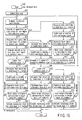
- FIG. 15 is a flow chart of determinations made if bars of a bar code are written, in the initialized state, in the BCA areas of a single- and double-layer rewritable media.
- a determining operation is started (step S50).
- the control section 420 first detects the BCA area (step S51). The control section 420 then evaluates the reproduction signal intensity using the method shown in FIG.
- step S52 If a signal from the bar code except for the bars in the BCA area has an intensity smaller than the reference value (NO in step S53), the control section 420 recognizes that the optical disk is a single H-L medium or a double-layer medium (step S54). Then, the control section 420 evaluates the reproduction intensity of the bar portion of the bar code (step S55). If the reproduction intensity of the bar portion is larger than the reference value 1, the control section 420 determines that the optical disk is a single-layer H-L medium (step S57). On the basis of the result of the determination, the control section 420 adjusts the gain of the amplifier of the BCA reproducing circuit 430 (step S58).
- the control section 420 then reproduces the book version contained in the bar code information (step S59). Then, the control section 420 checks whether or not the book version matches a single-layer H-L medium determined on the basis of the evaluation of the signal intensity (step S60). If the book version matches the single-layer H-L medium, the control section 420 activates a reproducing circuit for a single-layer H-L medium as previously described (step S61). If the book version does not match the single-layer H-L medium, the flow returns to the evaluation of the reproduction signal intensity. Further, when the reproduction intensity of the bar portion of the bar code is evaluated (step D56), if it is smaller than the reference value 1, then the control section 420 recognizes that the optical disk is a double-layer medium (step S62).
- control section 420 similarly adjusts the gain of the amplifier of the BCA reproducing circuit 430 (step S63).
- the control section 420 compares the L signal intensity with the reference value 2 (step S64). If the L signal has an intensity larger than the reference value 2 (or the L signal can be detected), the control section 420 recognizes that the optical disk is a double-layer L-H medium (step S66). The control section 420 then reproduces the book version information contained in the bar code information (step S67). The control section 420 checks whether the book version read corresponds to the double-layer L-H medium (step S68).
- the control section 420 activates a reproducing circuit for a double-layer L-H medium (step S69). Further, if the L signal has an intensity smaller than the reference value 2 (or the L signal cannot be detected), the control section 420 recognizes that the optical disk is a double-layer H-L medium (step S70). The control section 420 then reproduces the book version information contained in the bar code information (step S71). The control section 420 checks whether the book version read corresponds to the double-layer H-L medium (step S72). If the book version read corresponds to the double-layer H-L medium, the control section 420 activates a reproducing circuit for a double-layer H-L medium (step S73).
- the control section 420 determines that the optical disk is a single-layer L-H medium (step S74). As described above, for reproduction signals from the BCA, located in the innermost peripheral portion, if the rate at which a reproduction signal at a level above the reference value 1 is higher than that at which a reproduction signal at a level below the reference value 1, the control section 420 determines that the optical disk installed is a single-layer L-H. On the basis of the result of the determination, the control section 420 adjusts the gain of the amplifier of the BCA reproducing circuit 430 (step S75).
- the control section 420 then reproducibly reads the book version contained in the bar code information (step S76). Then, the control section 420 checks whether or not the book version matches a single-layer L-H medium (step S77). If the book version matches the single-layer L-H medium, the control section 420 activates a reproducing circuit for a single-layer L-H medium as previously described (step S78). During the above determining process, if the book version does not match the result of the determination based on the signal intensity, the flow returns to the reflection evaluation based on the reproduction signal intensity. Further, if the loop is repeated many times during the determining step, the control section 420 may output a disk recognition error to allow the disk to be removed.
- FIG. 16 is a flow chart of determinations made if a bar code is written, in the uninitialized state, in the BCA area of a single-layer medium. This process is basically the same as the determining step described above. However, the signal characteristics of a single-layer-H-L and L-H media are inverted, so that the results of determinations for the single layer are opposite to those shown in FIG. 15. Accordingly, the detailed description of operations is omitted.
- information can be recorded using the mixture of the four types of media, a single-layer L-H and H-L media and a double-layer H-L and L-H media. It is thus possible to select a medium having a recording film suitable for a recording purpose or application, from a group of a larger number of media. Further, the medium determination in the BCA area enables the information reproducing and recording circuit to be switched before entering the lead-in area. This allows recording speed information written in the system lead-in area to be read earlier. Therefore, set information recording at a specified speed before entering the data area. This allows the information recording circuit (the spindle motor driving circuit 415 and the like) to be quickly activated.
- the information recording circuit the spindle motor driving circuit 415 and the like
- FIG. 17 is a diagram showing the ranges of reflectances of recording films in a single- and double-layer rewritable media.
- H level the initialized state of a single-layer H-L medium does not overlap the initialized state (L level) of a single-layer L-H medium.
- the reflectance of the single-layer H-L medium in the initialized state (H level) is defined as the range of 12 to 40%.
- the reflectance of the single-layer L-H medium in the initialized state (L level) is defined as the range of 4 to 10%. Similarly, it is only necessary that the initialized state (H level) of the L0 layer of a double-layer H-L medium and the uninitialized state (H level) of the L0 layer of a double-layer L-H medium do not overlap the initialized state (H level) of a single-layer H-L medium. Therefore, as shown in FIG.
- the above medium determining method can be accurately executed in the BCA area when the reflectances of the L0 layer of the double-layer H-L medium in the initialized state (H level) and the L0 layer of the double-layer L-H medium in the uninitialized state (H level) are defined as the range of 4 to 10% similarly to the reflectance of the single-layer H-L medium in the initialized state (H level).
- the range of the reference value 1 is equal to the range of the reproduction signal intensity corresponding to a reflectance higher than 10% and lower than 12%.
- the reflectance of the L0 layer of a double-layer medium with a high reproduction signal quality is about 5 to 7% as described above. This definition of the reflectance ensures the reproduction signal quality.
- determinations can be made using only the book version information, the use of a medium with a defined reflectance enables the type of the medium to be determined on the basis of the reproduction signal intensity corresponding to the reflectance. This enables the gain of the amplifier to be pre-adjusted. Consequently, errors in reading of the book version information reproduced need not substantially be taken into account. Therefore, accurate reads can be accomplished. Since the book version information read can be compared with the result of the signal intensity evaluation, very accurate medium determinations can finally be made. Further, this determining method does not include any vertical operation of the lens as in the case of a focus search; it can be accomplished simply by processing the electric signals. Therefore, very quick determinations can be made.
- the reference value 2 is used to determine whether the optical disk is a double-layer.
- L-H or H-L medium that is, to compare L signals from these media. Accordingly, to provide this reference value, it is necessary that the reflectance of the double-layer L-H medium in the initialized state (L level) does not overlap the reflectance of the double-layer L-H medium in the uninitialized state (L level). It is essential to be able to detect the L signal from the L-H medium in the initialized state in order to carry out detection of addresses, focusing, and tracking. However, this does not apply to the H-L medium.
- the reflectance of the H-L medium at the L level is preferably as close to 0% as possible in order to improve the SN ratio and is at 2% or less. Accordingly, by defining the reflectance of the double-layer L-H medium in the initialized state (L level) as the range of 4 to 10% and defining the reflectance of the double-layer H-L medium in the uninitialized state (L level) as the range of 0 to 2%, it is possible to provide the range of the reference value 1 which is equal to the range of the reproduction signal range corresponding to a reflectance higher than 10% and lower than 12%. Consequently, a determining apparatus can be provided which uses the reference value 2 to determine whether the optical disk is a double-layer L-H or H-L medium.
- the signal intensity level corresponding to a detection limit corresponds to the reference value 2.
- the upper limit of the reflectance of the double-layer L-H medium in the initialized state is defined as 10% for the following reason: the uninitialized state corresponds to the H level and the reflectance in the uninitialized state is defined as the range of 4 to 10% in order to provide the reference value 1, so that the reflectance at the L level is always lower than that at the H level.
- medium comparisons are made using the fixed method for producing a BCA area.
- the production of a bar code in the BCA area can also be defined using the signal characteristic.
- the reproduction signal characteristic is fixed
- medium determinations can also be made using the above reference values and definitions for the reflectance of the medium reflection film.
- existing DVDs are generally produced so that the bar portions of the bar code provide L signals. Accordingly, description will be given of a determining scheme for setting the reproduction signal characteristic such that the bar portion provides the L signal, while the bar code except for the bar portions provides the H signal.
- the bar code is written by removing the recording film, the bar portion provides the L signal, while the bar code except for the bar portions provides the H signal. Accordingly, .determinations can be made using the scheme shown in FIG. 12.
- the bar code is written on the basis of the initialized state and uninitialized state of the recording film, then for both single- and double-layer media, the bar code portion is written to the H-L medium in the uninitialized state and to the L-H medium in the initialized state in order to obtain the same reproduction signal characteristic.
- FIG. 18 shows a determining scheme for a medium for which the bars in the bar code information are defined to provide L signals. Also in this case, the reference values 1 and 2 are used.
- the control section 420 starts a determining operation (step S110).
- the control section 420 detects the BCA (step S111) and then evaluates the reproduction signal intensity (step S112).
- the control section 420 first evaluates the H signal of the reproduction signal. If the H signal has an intensity smaller than the reference value 1 (NO in step S113), the control section 420 determines that the optical disk is a double-layer medium (step S114).
- the control section 420 adjusts the gain of the amplifier (step S115) and then evaluates the signal intensity of the L signal (step S116).
- the control section 420 determines that the optical disk is a double-layer L-H medium (step S118). Subsequently, the control section 420 further adjusts the amplifier gain circuit (step S119), and then reproduces the book version contained in the bar code information in the BCA area (step S120). The control section 420 then checks whether the optical disk is a double-layer L-H medium (step S121). If the result of the signal intensity evaluation matches the book version, the control section 420 activates a reproducing and recording circuit for a double-layer L-H medium as previously described (step S122).
- the control signal 420 recognizes that the optical disk is a double-layer H-L medium (step S123).
- the control section 420 similarly adjusts the amplifier gain circuit (step S124), and then reproduces the book version contained in the bar code information (step S125).
- the control section 420 checks whether the optical disk is a double-layer H-L medium (step S126). If the result of the signal intensity evaluation matches the book version, the control section 420 activates a reproducing and recording circuit for a double-layer H-L medium as previously described (step S127). If the result of the evaluation does not match in both cases, the flow returns to the initial signal intensity evaluation.
- the control signal 420 recognizes that the optical disk is a single-layer medium (step S128).
- the control section 420 adjusts the amplifier gain circuit (step S129), and then reproduces the book version contained in the bar code information (step S130).
- the control section 420 first checks whether the optical disk is a single-layer L-H medium (step S131). If the optical disk is a single-layer L-H medium, the control section 420 activates a reproducing and recording circuit for a single-layer L-H medium (step S132).
- the control section 420 checks whether the optical disk is a single-layer H-L medium (step S133). If the result of the evaluation matches the book version, the control section 420 activates a reproducing and recording circuit for a single-layer H-L medium (step S134). Also in this case, if the result of the evaluation does not match the book version, the flow returns to the initial signal intensity evaluation.
- (1) settings are made such that the reflectance of the single-layer H-L medium in the initialized state (H level) does not overlap the reflectances of the single-layer L-H medium in the initialized state (L level), the L0 layer of the double-layer L-H medium in the uninitialized state (H level) or the L0 layer of the double-layer H-L medium in the initialized state (H level).
- the reflectance of the L0 layer of the double-layer H-L medium in the uninitialized state (L level) is set to at most the detection limit value. This makes it possible to use the mixture of the four types of media conforming to the same standard for rewritable optical disks. Further, as shown in FIG.
- the reflectance of the single-layer H-L medium in the initialized state (H level) is defined as 12 to 40%.
- the reflectances of the single-layer L-H medium in the initialized state (L level), the L0 layer of the double-layer L-H medium in the uninitialized state (H level), and the L0 layer of the double-layer H-L medium in the initialized state (H level) are each defined as 4 to 10%. This makes it possible to produce a determining apparatus that meets conditions for avoiding the overlapping of the reflectances, while maintaining a high signal quality.
Landscapes
- Optical Recording Or Reproduction (AREA)
- Optical Record Carriers And Manufacture Thereof (AREA)
Abstract
Description
Claims (21)
- An optical disk apparatus in which a first, second, third, and fourth optical disks are selectively installed, the first and second optical disks having different recording film characteristics each other and both having a single-layer recording layer, the third and fourth optical disks having different recording film characteristics each other and both having a double-layer recording layer, the optical disk apparatus recording and reproducing information on and from the optical disk installed, the optical disk apparatus characterized by comprising:an optical head (202) which irradiates the optical disk installed with a light beam to provide a reproduction signal corresponding to reflected light; anda determining section (220, S53, S56) which uses the optical head to reproduce information from an innermost peripheral portion of the optical disk installed to determine which of the first to fourth optical disks has been installed, on the basis of the level of a reproduction signal obtained.
- The optical disk apparatus according to claim 1, characterized by further comprising:a reproduction signal processing section (430) which processes the reproduction signal provided by the optical head to extract information from the reproduction signal; anda control section (220, S58, S63, S75) which controls the reproduction signal processing section on the basis of the result of the determination by the determining section.
- The optical disk apparatus according to claim 2, characterized in that the determining section comprises:a section (S54, S74) which determines that the optical disk installed is the first optical disk if a rate at which a reproduction signal at a level above a first reference value is obtained from the innermost peripheral portion is higher than a rate at which a reproduction signal at a level below the first reference value is obtained from the innermost peripheral portion;a section (S56, S62) which determines that one of the second to fourth disk from which a reproduction signal level higher than the first reference value is obtained is the second optical disk; anda section (S65, S66) which determines that one of the third and fourth optical disks for which all of the reproduction signals obtained are at a signal level substantially above a second reference value smaller than the first reference value is the third optical disk.
- The optical disk apparatus according to claim 3, characterized in that the determining section determines the first optical disk to be a single-layer L-H medium (S74), the second optical disk to be a single-layer H-L medium (S57), the third optical disk to be a double-layer L-H medium (S66), and the fourth optical disk to be a double-layer H-L medium (S70).
- The optical disk apparatus according to claim 3, characterized in that the determining section determines the first optical disk to be a single-layer H-L medium (S104), the second optical disk to be a single-layer L-H medium (S87), the third optical disk to be a double-layer L-H medium (S96), and the fourth optical disk to be a double-layer H-L medium (S100).
- The optical disk apparatus according to claim 2, characterized in that the control section uses the optical head to reproduce information indicating the type of the optical disk itself recorded in the inner peripheral portion of the optical disk installed, and checks the information reproduced against the result of the determination by the determining section to determine which of the first to fourth optical disks has been installed (S60).
- The optical disk apparatus according to claim 3, characterized in that the control section uses the optical head to reproduce information indicating the type of the optical disk itself recorded in the inner peripheral portion of the optical disk installed, and checks the information reproduced against the result of the determination by the determining section to determine which of the first to fourth optical disks has been installed (S60).
- The optical disk apparatus according to claim 4, characterized in that the control section uses the optical head to reproduce information indicating the type of the optical disk itself recorded in the inner peripheral portion of the optical disk installed, and checks the information reproduced against the result of the determination by the determining section to determine which of the first to fourth optical disks has been installed (S60).
- The optical disk apparatus according to claim 5, characterized in that the control section uses the optical head to reproduce information indicating the type of the optical disk itself recorded in the inner peripheral portion of the optical disk installed, and checks the information reproduced against the result of the determination by the determining section to determine which of the first to fourth optical disks has been installed (S60).
- The optical disk apparatus according to claim 1, characterized in that the determining section comprises:a section (S54, S74) which determines that the optical disk installed is the first optical disk if a rate at which a reproduction signal at a level above a first reference value is obtained from the innermost peripheral portion is higher than a rate at which a reproduction signal at a level below the first reference value is obtained from the innermost peripheral portion;a section (S56, S62) which determines that one of the second to fourth disk from which a reproduction signal level higher than the first reference value is obtained is the second optical disk; anda section (S65, S66) which determines that one of the third and fourth optical disks for which all of the reproduction signals obtained are at a signal level substantially above a second reference value smaller than the first reference value is the third optical disk.
- The optical disk apparatus according to claim 10, characterized in that the determining section determines the first optical disk to be a single-layer L-H medium (S74), the second optical disk to be a single-layer H-L medium (S57), the third optical disk to be a double-layer L-H medium (S66), and the fourth optical disk to be a double-layer H-L medium (S70).
- The optical disk apparatus according to claim 10, characterized in that the determining section determines the first optical disk to be a single-layer H-L medium (S104), the second optical disk to be a single-layer L-H medium (S87), the third optical disk to be a double-layer L-H medium (S96), and the fourth optical disk to be a double-layer H-L medium (S100).
- The optical disk apparatus according to claim 11, characterized in that the control section uses the optical head to reproduce information indicating the type of the optical disk itself recorded in the inner peripheral portion of the optical disk installed, and checks the information reproduced against the result of the determination by the determining section to determine which of the first to fourth optical disks has been installed (S60).
- The optical disk apparatus according to claim 12, characterized in that the control section uses the optical head to reproduce information indicating the type of the optical disk itself recorded in the inner peripheral portion of the optical disk installed, and checks the information reproduced against the result of the determination by the determining section to determine which of the first to fourth optical disks has been installed (S60).
- The optical disk apparatus according to claim 1, characterized in that the determining section comprises:a judging section (S46) which judges that an optical disk from which a reproduction signal at a level above a predetermined reference value is obtained from the innermost peripheral portion is the first optical disk;a reproduction signal processing section (430) which processes the reproduction signal provided by the optical head to extract information from the reproduction signal; anda section which controls the reproduction signal processing section on the basis of the result of the judge by the judging section to reproduce the information indicating the type of the optical disk itself recorded in the inner peripheral portion of the optical disk installed, and identifies the optical disk installed on the basis of the information reproduced.
- A recording medium serving as an optical disk applied to the optical disk apparatus according to claim 1,
characterized in that the innermost peripheral portion has a BCA (Burst Cutting Area) and contains a double-layer L-H medium and a double-layer H-L medium, and
the range of light reflectance of an L0 layer of the double-layer L-H medium in an initialized state does not overlap the range of light reflectance of an L0 layer of the double-layer H-L medium in an uninitialized state. - The rewritable recording medium according to claim 16, characterized in that the light reflectance of the double-layer L-H medium in the initialized state is set within a range of 4 to 10%, and the light reflectance of the double-layer H-L medium in the uninitialized state is set within a range of 0 to 2%.
- The rewritable recording medium according to claim 16, characterized in that the recording medium includes a single-layer L-H medium and a single-layer H-L medium, and
the light reflectances of the single-layer L-H medium in the initialized state, the L0 layer of the double-layer H-L medium in the uninitialized state, and the L0 layer of the double-layer L-H medium in the uninitialized state do not overlap the light reflectance of the single-layer H-L medium in the initialized state. - The rewritable recording medium according to claim 18, characterized in that the light reflectances of the single-layer L-H medium in the initialized state and the L0 layers of the double-layer H-L medium and the double-layer L-H medium are each set t at 4 to 10%, and the light reflectance of the single-layer H-L medium in the initialized state is set within a range of 12 to 40%.
- A method for controlling an optical disk apparatus in which a first, second, third, and fourth optical disks are selectively installed, the first and second optical disks having different recording film characteristics each other and both having a single-layer recording layer, the third and fourth optical disks having different recording film characteristics each other and both having a double-layer recording layer, the method characterized by comprising:reproducing information from an innermost peripheral portion of one of the first to fourth optical disks which has been installed, to provide a reproduction signal;determining which of the first to fourth optical disks has been installed, on the basis of the level of the reproduction signal (S57, S66, S74); andcontrolling a signal processing section for reproducing information, on the basis of a result of the determination.
- The controlling method according to claim 20, characterized in that in the determining step comprises:determining that the optical disk installed is the first optical disk if a rate at which a reproduction signal at a level above a first reference value is obtained from the innermost peripheral portion is higher than a rate at which a reproduction signal at a level below the first reference value is obtained from the innermost peripheral portion (S74);determining that one of the second to fourth disk from which a reproduction signal level higher than the first reference value is obtained is the second optical disk (S57); anddetermining that one of the third and fourth optical disks for which all of the reproduction signals obtained are at a signal level substantially above a second reference value smaller than the first reference value is the third optical disk (S66).
Applications Claiming Priority (2)
| Application Number | Priority Date | Filing Date | Title |
|---|---|---|---|
| JP2003431437 | 2003-12-25 | ||
| JP2003431437A JP4342930B2 (en) | 2003-12-25 | 2003-12-25 | Optical disc apparatus, control method therefor, and recording medium |
Publications (3)
| Publication Number | Publication Date |
|---|---|
| EP1548731A2 true EP1548731A2 (en) | 2005-06-29 |
| EP1548731A3 EP1548731A3 (en) | 2006-10-25 |
| EP1548731B1 EP1548731B1 (en) | 2008-08-20 |
Family
ID=34545050
Family Applications (1)
| Application Number | Title | Priority Date | Filing Date |
|---|---|---|---|
| EP04029203A Expired - Lifetime EP1548731B1 (en) | 2003-12-25 | 2004-12-09 | Optical disk apparatus, method for controlling the same, and recording medium |
Country Status (7)
| Country | Link |
|---|---|
| US (1) | US7477586B2 (en) |
| EP (1) | EP1548731B1 (en) |
| JP (1) | JP4342930B2 (en) |
| KR (1) | KR100661383B1 (en) |
| CN (1) | CN100377245C (en) |
| DE (1) | DE602004015925D1 (en) |
| TW (1) | TWI314728B (en) |
Cited By (2)
| Publication number | Priority date | Publication date | Assignee | Title |
|---|---|---|---|---|
| EP1517323A3 (en) * | 2003-09-16 | 2006-09-13 | Kabushiki Kaisha Toshiba | Optical disk apparatus and method for controlling the same |
| EP2221812A3 (en) * | 2006-06-02 | 2011-01-05 | Kabushiki Kaisha Toshiba | Optical recording medium, information recording method, and information reproducing method |
Families Citing this family (5)
| Publication number | Priority date | Publication date | Assignee | Title |
|---|---|---|---|---|
| JP2005174528A (en) * | 2003-11-18 | 2005-06-30 | Hitachi Maxell Ltd | Optical disc, manufacturing method thereof, and recording / reproducing apparatus |
| EP2192582B1 (en) * | 2004-11-02 | 2011-08-31 | Panasonic Corporation | Optical recording medium and reproduction device |
| JP2007052862A (en) | 2005-08-18 | 2007-03-01 | Toshiba Corp | Optical disc, optical disc device, digital work publication |
| JP2010067313A (en) * | 2008-09-10 | 2010-03-25 | Sanyo Electric Co Ltd | Optical disk and optical disk apparatus |
| EP2402945A1 (en) | 2009-02-27 | 2012-01-04 | Mitsubishi Electric Corporation | Bca recording device for optical disc, optical disc reproducing device, and recordable optical disc |
Family Cites Families (39)
| Publication number | Priority date | Publication date | Assignee | Title |
|---|---|---|---|---|
| JP2809835B2 (en) * | 1990-07-30 | 1998-10-15 | 松下電器産業株式会社 | Optical disk device and optical disk |
| JPH05159326A (en) * | 1991-12-09 | 1993-06-25 | Matsushita Electric Ind Co Ltd | Focus control device |
| US5592448A (en) * | 1992-05-08 | 1997-01-07 | Hitachi, Ltd. | Access control apparatus for optical disk according change of track pitch |
| JP2835250B2 (en) | 1992-08-10 | 1998-12-14 | シャープ株式会社 | Light amount control device in optical disk recording / reproducing device |
| JPH06162743A (en) * | 1992-11-13 | 1994-06-10 | Sony Corp | Method and device for optical disk reproducing |
| JPH06333248A (en) * | 1993-02-24 | 1994-12-02 | Nippon Columbia Co Ltd | Optical recording and reproducing device |
| JPH0757442A (en) * | 1993-08-18 | 1995-03-03 | Sony Corp | Electronics |
| JPH08321129A (en) * | 1995-05-24 | 1996-12-03 | Sony Corp | Recording or playback device |
| US5831952A (en) * | 1995-07-27 | 1998-11-03 | Matsushita Electric Industrial Co., Ltd. | Optical disk thickness discriminating apparatus |
| JP2728065B2 (en) * | 1995-12-04 | 1998-03-18 | 日本電気株式会社 | Optical disc automatic discrimination method and system |
| TW453493U (en) * | 1996-02-13 | 2001-09-01 | Tokyo Shibaura Electric Co | Reproducing device of optical disk |
| KR200148566Y1 (en) * | 1996-10-11 | 1999-06-15 | 구자홍 | Device for discriminating kinds of disks for optical disc player |
| JP3619625B2 (en) * | 1996-10-25 | 2005-02-09 | ソニー株式会社 | Disk discriminating apparatus and method |
| JP3753267B2 (en) * | 1996-10-25 | 2006-03-08 | ソニー株式会社 | Disc recording / reproducing apparatus and method |
| KR19980030569A (en) * | 1996-10-30 | 1998-07-25 | 배순훈 | Disc determination method of digital video disc player |
| EP1589532A3 (en) * | 1996-12-19 | 2008-06-25 | Matsushita Electric Industrial Co., Ltd. | Optical disk and method for recording and reproducing write-once information on and from optical disk |
| KR100521667B1 (en) * | 1997-01-10 | 2006-01-27 | 소니 가부시끼 가이샤 | Optical Disc Device and Optical Disc Discrimination Method |
| JP3831063B2 (en) | 1997-04-25 | 2006-10-11 | パイオニア株式会社 | Optical disc discrimination device |
| KR19990004486A (en) * | 1997-06-28 | 1999-01-15 | 구자홍 | Method and apparatus for discriminating type of optical recording medium |
| JP3045041U (en) * | 1997-07-03 | 1998-01-23 | 船井テクノシステム株式会社 | Disk drive device |
| KR100255191B1 (en) * | 1997-12-31 | 2000-06-01 | 윤종용 | Disc and method for detecting kind of the disc in optical disc player |
| KR100524297B1 (en) * | 1998-03-24 | 2006-01-12 | 엘지전자 주식회사 | Rewritable disc and recording methods using the same |
| JPH11353785A (en) * | 1998-06-03 | 1999-12-24 | Sony Corp | Optical disc discriminating apparatus and discriminating method |
| JP2000215454A (en) | 1999-01-27 | 2000-08-04 | Matsushita Electric Ind Co Ltd | Optical disk recording apparatus and information recording method on optical disk |
| JP2000235732A (en) * | 1999-02-12 | 2000-08-29 | Sony Corp | Multilayer optical disc |
| JP2000311427A (en) * | 1999-04-27 | 2000-11-07 | Hitachi Ltd | Disk discriminating method and apparatus |
| JP2001118331A (en) * | 1999-10-19 | 2001-04-27 | Sony Corp | Recording device, recording / reproducing device, recording method |
| JP2001266367A (en) | 2000-03-17 | 2001-09-28 | Matsushita Electric Ind Co Ltd | Optical disk drive |
| JP3696044B2 (en) | 2000-04-21 | 2005-09-14 | 松下電器産業株式会社 | Optical disc apparatus and optical disc discrimination method |
| AU6425401A (en) * | 2000-06-16 | 2001-12-24 | Mitsubishi Chemical Corporation | Optical information recording medium |
| JP2002251777A (en) | 2001-02-21 | 2002-09-06 | Taiyo Yuden Co Ltd | Method of inspecting characteristic of optical head and method of correcting variation |
| JP3857905B2 (en) | 2001-10-31 | 2006-12-13 | 三洋電機株式会社 | Optical disc discrimination device |
| JP2003203423A (en) * | 2001-12-28 | 2003-07-18 | Pioneer Electronic Corp | Recording medium reproducing apparatus, reproducing method thereof, and program for reproducing recording medium |
| KR100857082B1 (en) * | 2002-02-07 | 2008-09-05 | 주식회사 히타치엘지 데이터 스토리지 코리아 | Disc Determination Method in Optical Disk Unit |
| TWI220512B (en) | 2002-06-27 | 2004-08-21 | Mediatek Inc | Method for controlling a compact disc recorder to record data onto a CD |
| KR100716966B1 (en) * | 2002-11-04 | 2007-05-10 | 삼성전자주식회사 | Optical disc having tracking polarity information, apparatus and method for recording and reproducing the same thereon |
| JP4060771B2 (en) * | 2003-09-16 | 2008-03-12 | 株式会社東芝 | Optical disc apparatus and control method thereof |
| JP2005174528A (en) * | 2003-11-18 | 2005-06-30 | Hitachi Maxell Ltd | Optical disc, manufacturing method thereof, and recording / reproducing apparatus |
| JP2005166096A (en) * | 2003-11-28 | 2005-06-23 | Toshiba Corp | Optical disc, optical disc device, optical disc recording / reproducing method, BCA code recording device, and BCA code recording method |
-
2003
- 2003-12-25 JP JP2003431437A patent/JP4342930B2/en not_active Expired - Fee Related
-
2004
- 2004-12-09 DE DE602004015925T patent/DE602004015925D1/en not_active Expired - Lifetime
- 2004-12-09 EP EP04029203A patent/EP1548731B1/en not_active Expired - Lifetime
- 2004-12-09 TW TW093138148A patent/TWI314728B/en not_active IP Right Cessation
- 2004-12-22 US US11/018,152 patent/US7477586B2/en not_active Expired - Fee Related
- 2004-12-23 KR KR1020040110992A patent/KR100661383B1/en not_active Expired - Fee Related
- 2004-12-24 CN CNB2004100114973A patent/CN100377245C/en not_active Expired - Fee Related
Cited By (4)
| Publication number | Priority date | Publication date | Assignee | Title |
|---|---|---|---|---|
| EP1517323A3 (en) * | 2003-09-16 | 2006-09-13 | Kabushiki Kaisha Toshiba | Optical disk apparatus and method for controlling the same |
| US7512046B2 (en) | 2003-09-16 | 2009-03-31 | Kabushiki Kaisha Toshiba | Optical disk apparatus and method for controlling the same |
| EP2221812A3 (en) * | 2006-06-02 | 2011-01-05 | Kabushiki Kaisha Toshiba | Optical recording medium, information recording method, and information reproducing method |
| US8509049B2 (en) | 2006-06-02 | 2013-08-13 | Kabushiki Kaisha Toshiba | Optical recording medium having intermediate layer of prescribed thickness and thickness range for use with 405nm laser |
Also Published As
| Publication number | Publication date |
|---|---|
| KR100661383B1 (en) | 2006-12-27 |
| JP4342930B2 (en) | 2009-10-14 |
| US7477586B2 (en) | 2009-01-13 |
| DE602004015925D1 (en) | 2008-10-02 |
| TWI314728B (en) | 2009-09-11 |
| KR20050065381A (en) | 2005-06-29 |
| EP1548731B1 (en) | 2008-08-20 |
| CN100377245C (en) | 2008-03-26 |
| EP1548731A3 (en) | 2006-10-25 |
| TW200531044A (en) | 2005-09-16 |
| JP2005190591A (en) | 2005-07-14 |
| US20050141379A1 (en) | 2005-06-30 |
| CN1637908A (en) | 2005-07-13 |
Similar Documents
| Publication | Publication Date | Title |
|---|---|---|
| US7710842B2 (en) | Optical disc apparatus and recording power determining method thereof | |
| US7936653B2 (en) | Information processing device, access device, recording medium, information processing method, and information processing program | |
| KR20000066576A (en) | Method for kind judging of optical record medium | |
| JP4060771B2 (en) | Optical disc apparatus and control method thereof | |
| US7369474B2 (en) | Method of and apparatus for differentiating between writable disc types | |
| EP1548731B1 (en) | Optical disk apparatus, method for controlling the same, and recording medium | |
| KR100430249B1 (en) | Apparatus for and method of determining information record medium | |
| JP2006059446A (en) | Optical disk medium and optical disk device | |
| US20070171794A1 (en) | Recording method, recording apparatus, and storage medium | |
| JP4553940B2 (en) | Method and drive for identifying the type of optical record carrier | |
| US20080192598A1 (en) | Recording System For Setting Write Strategy | |
| KR20040048476A (en) | Optical information reproducing apparatus and method | |
| JP4329731B2 (en) | Optical disk device | |
| JP2008234831A (en) | Rewritable recording medium | |
| US7830763B2 (en) | Optical recording medium, recording/reproducing apparatus provided with optimum power control (OPC) and method for controlling the same | |
| US7453776B2 (en) | Optical disc recording/reproducing apparatus and a method for determining write strategy thereof | |
| JP2006179127A (en) | Optical disc apparatus and control method thereof | |
| US20070076546A1 (en) | Optical disc apparatus and tracking error signal selecting method | |
| JP3996339B2 (en) | Optical recording / reproducing apparatus, optical disc discrimination method, and optical recording / reproducing apparatus start-up method | |
| US7961567B2 (en) | Optical disk apparatus | |
| US20070165492A1 (en) | Recording type optical disc apparatus and optical disc medium | |
| JP2004022010A (en) | Disc playback device |
Legal Events
| Date | Code | Title | Description |
|---|---|---|---|
| PUAI | Public reference made under article 153(3) epc to a published international application that has entered the european phase |
Free format text: ORIGINAL CODE: 0009012 |
|
| 17P | Request for examination filed |
Effective date: 20041209 |
|
| AK | Designated contracting states |
Kind code of ref document: A2 Designated state(s): AT BE BG CH CY CZ DE DK EE ES FI FR GB GR HU IE IS IT LI LT LU MC NL PL PT RO SE SI SK TR |
|
| AX | Request for extension of the european patent |
Extension state: AL BA HR LV MK YU |
|
| PUAL | Search report despatched |
Free format text: ORIGINAL CODE: 0009013 |
|
| AK | Designated contracting states |
Kind code of ref document: A3 Designated state(s): AT BE BG CH CY CZ DE DK EE ES FI FR GB GR HU IE IS IT LI LT LU MC NL PL PT RO SE SI SK TR |
|
| AX | Request for extension of the european patent |
Extension state: AL BA HR LV MK YU |
|
| 17Q | First examination report despatched |
Effective date: 20061218 |
|
| AKX | Designation fees paid |
Designated state(s): DE FR GB |
|
| GRAP | Despatch of communication of intention to grant a patent |
Free format text: ORIGINAL CODE: EPIDOSNIGR1 |
|
| GRAS | Grant fee paid |
Free format text: ORIGINAL CODE: EPIDOSNIGR3 |
|
| GRAA | (expected) grant |
Free format text: ORIGINAL CODE: 0009210 |
|
| AK | Designated contracting states |
Kind code of ref document: B1 Designated state(s): DE FR GB |
|
| REG | Reference to a national code |
Ref country code: GB Ref legal event code: FG4D |
|
| REF | Corresponds to: |
Ref document number: 602004015925 Country of ref document: DE Date of ref document: 20081002 Kind code of ref document: P |
|
| PLBE | No opposition filed within time limit |
Free format text: ORIGINAL CODE: 0009261 |
|
| STAA | Information on the status of an ep patent application or granted ep patent |
Free format text: STATUS: NO OPPOSITION FILED WITHIN TIME LIMIT |
|
| 26N | No opposition filed |
Effective date: 20090525 |
|
| PGFP | Annual fee paid to national office [announced via postgrant information from national office to epo] |
Ref country code: GB Payment date: 20131204 Year of fee payment: 10 Ref country code: DE Payment date: 20131204 Year of fee payment: 10 |
|
| PGFP | Annual fee paid to national office [announced via postgrant information from national office to epo] |
Ref country code: FR Payment date: 20131209 Year of fee payment: 10 |
|
| REG | Reference to a national code |
Ref country code: DE Ref legal event code: R119 Ref document number: 602004015925 Country of ref document: DE |
|
| GBPC | Gb: european patent ceased through non-payment of renewal fee |
Effective date: 20141209 |
|
| REG | Reference to a national code |
Ref country code: FR Ref legal event code: ST Effective date: 20150831 |
|
| PG25 | Lapsed in a contracting state [announced via postgrant information from national office to epo] |
Ref country code: GB Free format text: LAPSE BECAUSE OF NON-PAYMENT OF DUE FEES Effective date: 20141209 Ref country code: DE Free format text: LAPSE BECAUSE OF NON-PAYMENT OF DUE FEES Effective date: 20150701 |
|
| PG25 | Lapsed in a contracting state [announced via postgrant information from national office to epo] |
Ref country code: FR Free format text: LAPSE BECAUSE OF NON-PAYMENT OF DUE FEES Effective date: 20141231 |