EP1548685B1 - Vehicle driving assist system - Google Patents
Vehicle driving assist system Download PDFInfo
- Publication number
- EP1548685B1 EP1548685B1 EP04030179A EP04030179A EP1548685B1 EP 1548685 B1 EP1548685 B1 EP 1548685B1 EP 04030179 A EP04030179 A EP 04030179A EP 04030179 A EP04030179 A EP 04030179A EP 1548685 B1 EP1548685 B1 EP 1548685B1
- Authority
- EP
- European Patent Office
- Prior art keywords
- visual perception
- obstacle
- vehicle
- external environment
- assist system
- Prior art date
- Legal status (The legal status is an assumption and is not a legal conclusion. Google has not performed a legal analysis and makes no representation as to the accuracy of the status listed.)
- Expired - Fee Related
Links
Images


Classifications
-
- B—PERFORMING OPERATIONS; TRANSPORTING
- B60—VEHICLES IN GENERAL
- B60W—CONJOINT CONTROL OF VEHICLE SUB-UNITS OF DIFFERENT TYPE OR DIFFERENT FUNCTION; CONTROL SYSTEMS SPECIALLY ADAPTED FOR HYBRID VEHICLES; ROAD VEHICLE DRIVE CONTROL SYSTEMS FOR PURPOSES NOT RELATED TO THE CONTROL OF A PARTICULAR SUB-UNIT
- B60W10/00—Conjoint control of vehicle sub-units of different type or different function
- B60W10/18—Conjoint control of vehicle sub-units of different type or different function including control of braking systems
-
- G—PHYSICS
- G08—SIGNALLING
- G08G—TRAFFIC CONTROL SYSTEMS
- G08G1/00—Traffic control systems for road vehicles
- G08G1/16—Anti-collision systems
- G08G1/165—Anti-collision systems for passive traffic, e.g. including static obstacles, trees
-
- G—PHYSICS
- G08—SIGNALLING
- G08G—TRAFFIC CONTROL SYSTEMS
- G08G1/00—Traffic control systems for road vehicles
- G08G1/16—Anti-collision systems
- G08G1/166—Anti-collision systems for active traffic, e.g. moving vehicles, pedestrians, bikes
-
- B—PERFORMING OPERATIONS; TRANSPORTING
- B60—VEHICLES IN GENERAL
- B60T—VEHICLE BRAKE CONTROL SYSTEMS OR PARTS THEREOF; BRAKE CONTROL SYSTEMS OR PARTS THEREOF, IN GENERAL; ARRANGEMENT OF BRAKING ELEMENTS ON VEHICLES IN GENERAL; PORTABLE DEVICES FOR PREVENTING UNWANTED MOVEMENT OF VEHICLES; VEHICLE MODIFICATIONS TO FACILITATE COOLING OF BRAKES
- B60T2201/00—Particular use of vehicle brake systems; Special systems using also the brakes; Special software modules within the brake system controller
- B60T2201/02—Active or adaptive cruise control system; Distance control
Definitions
- the present invention relates to a vehicle driving assist system that activates collision avoiding means, such as an alarm device and a vehicle speed limiting device, when a distance between the vehicle and a three-dimensional (3-D) obstacle ahead of the vehicle reaches a required activation distance.
- collision avoiding means such as an alarm device and a vehicle speed limiting device
- 3-D obstacles such as preceding vehicles, oncoming vehicles, and pedestrians, that could possibly collide with one's own vehicle are detected by a laser radar or the like mounted on one's own vehicle, a physical distance between the 3-D obstacle and one's own vehicle is detected, and a warning is provided to a driver by an alarm if the distance is short.
- Document EP 1 223 083 describes a driving support system which enables a driver to appropiately confirm the vehicle surrounding's conditions.
- Japanese Unexamined Patent Application Publication No. 6-243398 discloses a technology in which the degree of fatigue of the driver is detected and, if the degree of fatigue is high, the delay in recognizing a 3-D obstacle is prevented in advance by increasing the output power of a sensor that detects the presence of an object around a vehicle and a distance from the vehicle and by increasing the detection area.
- the perception ability of the driver is decreased not only by the degree of fatigue of the driver but also by the complexity of the visual environment.
- 3-D objects such as electric poles and architectural structures are in the field of view in the region of a 3-D obstacle or when 3-D objects having a similar shape or size to the 3-D obstacle exist in the background of the 3-D obstacle, the 3-D obstacle blends in with the 3-D objects or is hidden by the 3-D objects. Therefore, the perception ability is decreased.
- almost all drivers are unaware of the decrease in their perception ability of a 3-D obstacle caused by a complex visual environment.
- a vehicle driving assist system for assisting a driver in driving a vehicle by recognizing an external environment of the vehicle, comprising, imaging means for imaging the external environment of the vehicle, 3-D obstacle detection means for detecting a 3-D obstacle inhibiting the driving direction of the vehicle based on an image of the external environment captured by the imaging means, visual perception difficulty determination means for determining, based on the captured image of the external environment, whether the external environment is in a condition that makes visual perception of the 3-D obstacle difficult, activating collision avoiding means for controlling the vehicle so as to avoid the collision with the 3-D obstacle, and control means for, upon detection of the 3-D obstacle by the 3-D obstacle detection means, controlling the operation of the activating collision avoiding means based on the determination result of the visual perception difficulty determination means.
- Such a configuration can estimate the decrease in perception ability of the driver caused by the external environment and can appropriately assist the driver in driving the vehicle.
- a vehicle 1 such as a motor vehicle, includes a vehicle active drive assist system 2 (hereinafter referred to as an "ADA system") that actively assists a driver of the vehicle 1.
- the ADA system 2 has an alarm function for providing a warning to the driver in the case of there being a short distance between the vehicle 1 and a 3-D obstacle ahead of the vehicle 1 and a speed-limiting function for activating a brake.
- the ADA system 2 includes a stereo camera 3 serving as an imaging unit, an image processing unit 4, an external environment recognition unit 5, and a controller 6.
- a vehicle speed sensor 7 is connected to the controller 6.
- an alarm unit 8, such as a buzzer and a lamp, and a brake applying unit 9 serving as a vehicle speed limiting unit are connected to the controller 6.
- the brake is operated by an actuating signal output from the brake applying unit 9.
- the alarm unit 8 and the brake applying unit 9 constitute collision avoiding means.
- the collision avoiding means may be either one of the alarm unit 8 and the brake applying unit 9.
- the stereo camera 3 is mounted in the vicinity of a rear-view mirror in a passenger compartment of the vehicle 1 and includes right and left cameras having an built-in image sensor, such as a charge coupled device (CCD) and a complementary metal-oxide semiconductor (CMOS), that is, the stereo camera 3 includes a main camera, for example, a right-side camera, and a sub camera, for example, a left-side camera.
- the main camera of the stereo camera 3 acquires a reference image and the sub camera acquires a comparative image.
- the image processing unit 4 converts analog images of the external environment (primarily images ahead of the vehicle 1) captured by the main and sub cameras to digital images having a predetermined luminance gradation (i.e., A/D conversion), and adjusts the converted digital images through a process such as luminance adjustment and image geometric conversion. Then, the image processing unit 4 creates the reference image from the image captured by the main camera and the comparative image from the image captured by the sub camera, and stores both images in an image memory.
- A/D conversion luminance gradation
- the external environment recognition unit 5 has a 3-D object detecting function for detecting at least one of 3-D objects ahead of or around the vehicle 1 based on the images of the external environment processed by the image processing unit 4, a 3-D obstacle detecting function for detecting a 3-D obstacle that blocks the driving direction of the vehicle 1 from the 3-D objects, and a visual recognition problem determining function for determining, based on the image of the external environment, whether the external environment is in a condition that makes visual perception of the 3-D obstacle difficult.
- a parallax between the reference image and the comparative image stored in the image memory is calculated.
- Distance information on the entire image is then determined from the parallax, that is, the amount of shift in the horizontal direction between the reference image and the comparative image by using the principal of triangulation, and 3-D distance distribution data (a distance image) is generated.
- the 3-D distance distribution data is processed to detect a 3-D object ahead in a driving lane, such as a motor vehicle ahead, a parked motor vehicle, an oncoming motor vehicle, a pedestrian, an electric pole, and a building. Also, the shape of the driving lane is detected.
- the 3-D object is detected by, for example, extracting horizontal edges in the horizontal direction and vertical edges in the vertical direction from the image.
- the method for extracting the edges will be briefly described next. Since a method for extracting the vertical edges is identical to that for the horizontal edges, only a method for extracting the horizontal edges will be described.
- a filtering process is carried out for each pixel in a processing area determined in the reference image in the horizontal direction so as to enhance part of the edges having a luminance difference in the horizontal direction.
- the filtering process includes, for example, a filtering process using the Sobel operation.
- a luminance histogram is calculated. Based on the histogram, binary processing is carried out for the pixels using a threshold luminance value that makes the ratio of the number of low luminance pixels against the number of high luminance pixels to be a predetermined value. Pixels having a value of "1" after the binary processing, that is, edge points are extracted and contiguous edge points are grouped into one horizontal edge.
- the method for grouping edge points includes, for example, a labeling process using a template and a process in which edge points are approximated to a straight line using the least-square method.
- a plurality of 3-D objects displayed on a screen are detected from horizontal edges and vertical edges at the same distances based on the extracted horizontal edges, the vertical edges extracted in the same manner as the horizontal edges, and the distance data.
- the external environment recognition unit 5 extracts a 3-D obstacle that could possibly collide with the vehicle 1 from the detected 3-D objects. The external environment recognition unit 5 then determines whether the outline of the 3-D obstacle is hidden by other 3-D objects, whether a plurality of 3-D objects having a similar shape to the 3-D obstacle exists, whether a plurality of moving 3-D objects exist, and whether the background of the 3-D obstacle is complex from a vehicle 1 driver's standpoint.
- the external environment recognition unit 5 determines that the external environment is in a condition that makes visual perception difficult. That is, the external environment recognition unit 5 determines that the external environment is in a condition in which the driver's ability to visually perceive the 3-D obstacle is decreased by the presence of other 3-D objects.
- a moving vector of a 3-D object is calculated from time-series positional data of the 3-D object in the reference image captured by the main camera of the stereo camera 3.
- a 3-D object that could possibly collide with the vehicle 1 is extracted based on the relationship between a traveling direction of the vehicle 1 and the moving vector of the 3-D object. This 3-D object is regarded as a 3-D obstacle.
- the extracted 3-D obstacle may be a motor vehicle traveling ahead of the vehicle 1 in the driving lane, a parked motor vehicle ahead of the vehicle 1 in the driving lane, a motor vehicle traveling in an oncoming driving lane, a pedestrian, a bicycle, or a motorcycle on the shoulder of the driving lane ahead of the vehicle 1.
- a 3-D object having a change in time-series positional data is extracted.
- the extracted 3-D object is regarded as a moving object.
- the controller 6 has a setting function for setting a required activation distance, in other words, a required working distance or a required operating distance.
- the setting function calculates a required alarm working distance Dw between the vehicle 1 and the 3-D obstacle, at which the alarm unit 8 is worked when the vehicle 1 approaches the 3-D obstacles, and a required brake operating distance Dn, at which a brake is operated by outputting an actuating signal to the brake applying unit 9 when the vehicle 1 approaches the 3-D obstacle, based on a vehicle speed Ve of the vehicle 1 detected by the vehicle speed sensor 7.
- the controller 6 extends the required alarm working distance Dw and the required brake operating distance Dn by a predetermined value. Accordingly, in a condition that makes visual perception difficult, activation timings of the alarm unit 8 and the brake are set ahead.
- a driving assist routine shown in Fig. 2 is executed at predetermined intervals. Firstly, at step S1, image data ahead of the vehicle 1, which is captured by the stereo camera 3 comprising the main camera and the sub camera, is input. At step S2, the vehicle speed Ve detected by the vehicle speed sensor 7 is input.
- step S3 the image data is processed in a predetermined manner to detect a 3-D object. Since this process is described above, a description is not included here.
- step S4 it is determined whether a 3-D obstacle exists in the detected 3-D objects. If a 3-D obstacle is found, the process proceeds to step S5. Otherwise, the process exits the routine. Since the extraction process of a 3-D obstacle is described above, a description is not included here.
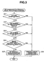
- step S5 it is determined whether the external environment ahead of the vehicle 1 is in a condition that makes visual perception difficult. This is determined by a visual perception difficulty determination subroutine shown in Fig. 3.
- step S21 it is determined whether a 3-D object that inhibits the recognition of an outline of the extracted 3-D obstacle (hereinafter referred to as an "outline inhibitor") exists.
- an outline inhibitor For example, in Fig. 4, a pedestrian W who is moving on the shoulder of the driving lane is a 3-D obstacle and an electric pole P is an outline inhibitor. A part of the outline of the pedestrian W is hidden by the electric pole P. Therefore, it is difficult for the driver to determine or estimate the moving direction of the pedestrian W accurately.
- step S21 when the 3-D obstacle is extracted, distance values at the right and the left of the 3-D obstacle in the horizontal direction are detected based on the image captured by the stereo camera 3. If the distance value at the right or the left of the 3-D obstacle in the horizontal direction is smaller than a distance value of the 3-D obstacle, it is determined that a part of the 3-D obstacle is hidden by another 3-D object and, therefore, an outline inhibitor exists.
- the outline inhibitor is not limited to the electric pole P.
- a pole of a traffic sign, a wall, a roadside tree, and a stake may be outline inhibitors.
- step S26 information indicating that a difficult visual perception condition exists in the external environment ahead of the vehicle 1 is stored in a volatile memory. Then, the process exits the routine.
- step S22 it is determined whether more than or equal to a predetermined number n1 of 3-D objects having a similar shape to the 3-D obstacle (hereinafter referred to as a "similar shaped object") exist.
- the 3-D obstacle is a preceding vehicle Cf traveling ahead of the vehicle 1 or an oncoming vehicle Co, as shown in Fig. 5A. Since the size and pattern of buildings E positioned in line far from the vehicle 1 are similar to those of the vehicles Cf and Co, the vehicles Cf and Co are blended in with the far buildings E and, thus, the driver sometimes cannot distinguish the vehicles Cf and Co clearly from other 3-D objects.
- a 3-D obstacle is the pedestrian W and a plurality of slender structures F, such as an electric pole and a telephone booth, is standing at the shoulder of the driving lane
- the pattern of the shoulder of the pedestrian W is similar to that of the structures F. Accordingly, the pedestrian W is blended in with the structures F and, thus, the driver sometimes cannot recognize the pedestrian W.
- step S22 based on the extracted vertical edges and horizontal edges, the shapes of the 3-D obstacle (the preceding vehicle Cf and the oncoming vehicle Co, or the pedestrian W) and 3-D objects (buildings E and F) are recognized. It is then determined whether an object having a similar shape to the 3-D obstacle (a similar shaped object) exists. If a similar shaped object exists, the number a of similar shaped objects is counted. If the count number a is more than or equal to the predetermined number n1 (i.e., n1 ⁇ a), it is determined that a similar shaped object exists and the process jumps to step S26, where information indicating that a difficult visual perception condition exists in the external environment ahead of the vehicle 1 is stored in a volatile memory. Then, the process exits the routine.
- n1 i.e., n1 ⁇ a
- step S23 it is determined whether the number b of moving objects is greater than or equal to a predetermined number n2.
- the 3-D objects are the pedestrians W walking on the shoulder of the driving lane and one of the pedestrians W is a 3-D obstacle
- the driver recognizes all the movements of the pedestrians W and the 3-D obstacle to determine the possibility of collision. Accordingly, the determination is sometimes delayed.
- the movements of the pedestrians W sometimes impair the recognition of an amount of the movement of the 3-D obstacle.
- step S23 the number of moving objects is counted. If the count number b is greater than or equal to the predetermined number n2 (i.e., n2 ⁇ b), it is determined that a plurality of moving objects exists and the process jumps to step S26, where information indicating that a difficult visual perception condition exists in the external environment ahead of the vehicle 1 is stored in the volatile memory. Then, the process exits the routine.
- n2 predetermined number
- step S24 the complexity of the image is determined.
- the complexity of the image is determined by using the number c of the vertical edges and the number d of the horizontal edges.
- step S24 the number c of vertical edges and the number d of horizontal edges are counted. If the number c is greater than or equal to a predetermined number n3 or the number d is greater than or equal to a predetermined number n4 (i.e., n3 ⁇ c or n4 ⁇ d), it is determined that the image is complex and the process jumps to step S26, where information indicating that a difficult visual perception condition exists in the external environment ahead of the vehicle 1 is stored in the volatile memory. Then, the process exits the routine.
- n3 ⁇ c or n4 ⁇ d i.e., n3 ⁇ c or n4 ⁇ d
- step S25 information indicating that no difficult visual perception condition exists is stored in the volatile memory. Then, the process exits the routine.
- step S6 the result of the determination of the visual perception difficulty determination subroutine shown in Fig. 3 is input, and then it is determined whether a difficult visual perception condition exists. If a difficult visual perception condition exists, the process proceeds to step S7. In contrast, if no difficult visual perception condition exists, the process proceeds to step S8.
- allowance values L1 and L2 which are input when the required alarm working distance Dw and the required brake operating distance Dn are calculated as will be described below, are updated so as to be added by a predetermined correction value ⁇ L, for example, about 2 to 5 m (i.e., L1 ⁇ L1 + ⁇ L, L2 ⁇ L2 + ⁇ L).
- a predetermined correction value ⁇ L for example, about 2 to 5 m (i.e., L1 ⁇ L1 + ⁇ L, L2 ⁇ L2 + ⁇ L).
- the correction value ⁇ L is a constant value. However, it may be a variable value varying in accordance with the driving conditions, such as a vehicle speed.
- the correction values ⁇ L may be different for the allowance values L1 and L2.
- Dw Dsw - Ve 2 / 2 ⁇ Ae + ⁇ VQ 2 / 2 ⁇ AQ ⁇ + L ⁇ 1
- Dn DsQ - Ve 2 / 2 ⁇ Ae + ⁇ VQ 2 / 2 ⁇ AQ ⁇ + L ⁇ 2
- the second terms ( ⁇ Ve 2 / (2 ⁇ Ae) ⁇ ) represent a braking distance when the vehicle 1 is braked from a vehicle speed Ve of the vehicle 1 at a deceleration Ae.
- the deceleration Ae is determined considering braking power and ride quality of the vehicle 1. For example, the deceleration Ae is determined as about -1.0 m/s 2 .
- the third terms represent an estimated braking distance assuming that the 3-D obstacle brakes at a deceleration AQ.
- the value of AQ is set to a constant value of about -6.0 m/s 2 .
- the 3-D obstacle is not limited to the preceding vehicle.
- the 3-D obstacle includes the oncoming vehicle and the pedestrian. Therefore, AQ may be set to 1.0 m/s 2 .
- the fourth terms (L1 and L2) are allowance values used for setting the required alarm working distance Dw and the required brake operating distance Dn, respectively.
- the initial values are:
- step S9 a distance Dr between the vehicle 1 and the 3-D obstacle (hereinafter referred to as an "object distance”) is compared with the required alarm working distance Dw to determine whether the object distance Dr is shorter than the required alarm working distance Dw.
- the object distance Dr is determined with reference to the corresponding distance data in the image captured by the stereo camera 3 when the 3-D obstacle is extracted.
- step S10 the actuating signal is delivered to the alarm unit 8 to work an alarm.
- the alarm unit 8 then outputs an alarm to the driver.
- step S11 the object distance Dr is compared with the required brake operating distance Dn. If Dr ⁇ Dn, the process exits the routine since the object distance Dr has some allowance. In contrast, if Dr ⁇ Dn, the object distance Dr is shorter than the required brake operating distance Dn. Accordingly, the process proceeds to step S12, where the actuating signal is delivered to the brake applying unit 9 to activate a brake. The process then exits the routine.
- the required alarm working distance Dw and the required brake operating distance Dn are extended by the correction value ⁇ L compared to those in which no difficult visual perception condition exists.
- the alarm unit 8 and the brake are operated at an early timing, thereby avoiding any accident that may arise and increasing the safety.
- the 3-D object in order to determine similar shaped objects, is compared with the 3-D obstacle by using vertical edges and horizontal edges thereof.
- the similar shaped object may be determined by extracting the 3-D object having a similar width defined by the vertical edges without using the horizontal edges.
- Figs. 9A and 9B show a situation in which the presence of 3-D objects having the similar width makes the recognition of the 3-D obstacle difficult.
- Fig. 9A shows an image of a motorcycle Ho traveling near 3-D structures (3-D objects), such as electric poles.
- Fig. 9B schematically shows vertical edges in the image shown in Fig. 9A.
- FIG. 10A shows an image of a vehicle Io traveling at the same place shown in Fig. 9A.
- Fig. 10B schematically shows vertical edges in the image shown in Fig. 10A.
- the motorcycle Ho shown in Figs. 9A and 9B and the vehicle Io shown in Figs. 10A and 10B are 3-D obstacles whose heights are different relative to the nearby structures (3-D objects).
- the comparison between Figs. 9B and 10B indicates that the 3-D obstacle in Fig. 10B (i.e., Io) is clearly defined against other 3-D objects, while the 3-D obstacle in Fig. 9B (i.e. Ho) is blended in with the other 3-D objects and, therefore, is difficult to recognize.
- the presence of similar shaped objects having only the similar width makes it difficult for the driver to perceive the 3-D obstacle. Accordingly, if the 3-D object having the similar width is defined as the similar shaped object even though the height of the 3-D object is different, the safety can be further increased in a preventive manner.
- the present invention is not limited to the above-described embodiments.
- the image captured by the stereo camera 3 may be divided into a driving lane region 11, a left landscape region 12, and a right landscape region 13, and the presence of a difficult visual perception condition may be checked for each region.
- the driving lane region 11 may be divided into a driving lane region 11a of the vehicle 1 and an oncoming driving lane region 11b of the oncoming vehicle, and the presence of the difficult visual perception condition may be checked for each region.
- the main camera and sub camera included in the stereo camera 3 may be color video cameras.
- the visual perception difficulty determination subroutine shown in Fig. 3 may include a determination condition indicating that a visual recognition problem exists if an image captured by the stereo camera 3 has a predetermined ratio of substantially the same color data area as the 3-D obstacle.
Description
- The present invention relates to a vehicle driving assist system that activates collision avoiding means, such as an alarm device and a vehicle speed limiting device, when a distance between the vehicle and a three-dimensional (3-D) obstacle ahead of the vehicle reaches a required activation distance.
- A variety of vehicle driving assist systems have been proposed in which 3-D obstacles such as preceding vehicles, oncoming vehicles, and pedestrians, that could possibly collide with one's own vehicle are detected by a laser radar or the like mounted on one's own vehicle, a physical distance between the 3-D obstacle and one's own vehicle is detected, and a warning is provided to a driver by an alarm if the distance is short.
- Document
EP 1 223 083 describes a driving support system which enables a driver to appropiately confirm the vehicle surrounding's conditions. - On the other hand, a driver's perception ability to recognize the presence of a 3-D obstacle such as another vehicle and a pedestrian decreases in accordance with the degree of fatigue of the driver. To solve this problem, for example,
Japanese Unexamined Patent Application Publication No. 6-243398 - However, it is known that the perception ability of the driver is decreased not only by the degree of fatigue of the driver but also by the complexity of the visual environment. For example, when 3-D objects such as electric poles and architectural structures are in the field of view in the region of a 3-D obstacle or when 3-D objects having a similar shape or size to the 3-D obstacle exist in the background of the 3-D obstacle, the 3-D obstacle blends in with the 3-D objects or is hidden by the 3-D objects. Therefore, the perception ability is decreased. However, almost all drivers are unaware of the decrease in their perception ability of a 3-D obstacle caused by a complex visual environment.
- To solve this problem, one possibility is to increase in advance the sensitivity in detecting an obstacle by, for example, a laser radar. However, this solution sometimes provides over-assistance. Also, it disadvantageously decreases the accuracy of detection, and therefore, this solution decreases the usability and is not so practical.
- Accordingly, it is an object of the present invention to provide a vehicle driving assist system that can estimate the decrease in perception ability of the driver caused by the external environment and appropriately assist the driver in driving the vehicle.
- According to the present invention, a vehicle driving assist system for assisting a driver in driving a vehicle by recognizing an external environment of the vehicle, comprising, imaging means for imaging the external environment of the vehicle, 3-D obstacle detection means for detecting a 3-D obstacle inhibiting the driving direction of the vehicle based on an image of the external environment captured by the imaging means, visual perception difficulty determination means for determining, based on the captured image of the external environment, whether the external environment is in a condition that makes visual perception of the 3-D obstacle difficult, activating collision avoiding means for controlling the vehicle so as to avoid the collision with the 3-D obstacle, and control means for, upon detection of the 3-D obstacle by the 3-D obstacle detection means, controlling the operation of the activating collision avoiding means based on the determination result of the visual perception difficulty determination means.
- Such a configuration can estimate the decrease in perception ability of the driver caused by the external environment and can appropriately assist the driver in driving the vehicle.
- The above and other objects, features and advantages of the invention will become more clearly understood from the following description referring to the accompanying drawings.
-
- Fig. 1 is a block diagram of a vehicle in which a vehicle driving assist system is mounted;
- Fig. 2 is a flow chart of a vehicle driving assist routine;
- Fig. 3 is the flow chart of a visual perception difficulty determination subroutine;
- Fig. 4 is a diagram explaining an image including an outline inhibitor;
- Figs. 5A and 5B are diagrams explaining two patterns of images including similar shaped objects;
- Fig. 6 is a diagram explaining an image including a plurality of moving objects;
- Fig. 7 is a diagram explaining a complex image;
- Figs. 8A and 8B are diagrams explaining two patterns of divided regions of an image;
- Fig. 9A shows an image of a motorcycle traveling near architectural structures;
- Fig. 9B schematically shows vertical edges in the image shown in Fig. 9A;
- Fig. 10A shows an image of a vehicle traveling near architectural structures; and
- Fig. 10B schematically shows vertical edges in the image shown in Fig. 10A.
- Referring to Fig. 1, a vehicle 1, such as a motor vehicle, includes a vehicle active drive assist system 2 (hereinafter referred to as an "ADA system") that actively assists a driver of the vehicle 1. The ADA
system 2 has an alarm function for providing a warning to the driver in the case of there being a short distance between the vehicle 1 and a 3-D obstacle ahead of the vehicle 1 and a speed-limiting function for activating a brake. - The ADA
system 2 includes astereo camera 3 serving as an imaging unit, animage processing unit 4, an externalenvironment recognition unit 5, and acontroller 6. A vehicle speed sensor 7 is connected to thecontroller 6. In addition, an alarm unit 8, such as a buzzer and a lamp, and abrake applying unit 9 serving as a vehicle speed limiting unit are connected to thecontroller 6. The brake is operated by an actuating signal output from thebrake applying unit 9. The alarm unit 8 and thebrake applying unit 9 constitute collision avoiding means. However, the collision avoiding means may be either one of the alarm unit 8 and thebrake applying unit 9. - The
stereo camera 3 is mounted in the vicinity of a rear-view mirror in a passenger compartment of the vehicle 1 and includes right and left cameras having an built-in image sensor, such as a charge coupled device (CCD) and a complementary metal-oxide semiconductor (CMOS), that is, thestereo camera 3 includes a main camera, for example, a right-side camera, and a sub camera, for example, a left-side camera. The main camera of thestereo camera 3 acquires a reference image and the sub camera acquires a comparative image. - The
image processing unit 4 converts analog images of the external environment (primarily images ahead of the vehicle 1) captured by the main and sub cameras to digital images having a predetermined luminance gradation (i.e., A/D conversion), and adjusts the converted digital images through a process such as luminance adjustment and image geometric conversion. Then, theimage processing unit 4 creates the reference image from the image captured by the main camera and the comparative image from the image captured by the sub camera, and stores both images in an image memory. - The external
environment recognition unit 5 has a 3-D object detecting function for detecting at least one of 3-D objects ahead of or around the vehicle 1 based on the images of the external environment processed by theimage processing unit 4, a 3-D obstacle detecting function for detecting a 3-D obstacle that blocks the driving direction of the vehicle 1 from the 3-D objects, and a visual recognition problem determining function for determining, based on the image of the external environment, whether the external environment is in a condition that makes visual perception of the 3-D obstacle difficult. - More specifically, a parallax between the reference image and the comparative image stored in the image memory is calculated. Distance information on the entire image is then determined from the parallax, that is, the amount of shift in the horizontal direction between the reference image and the comparative image by using the principal of triangulation, and 3-D distance distribution data (a distance image) is generated. Subsequently, the 3-D distance distribution data is processed to detect a 3-D object ahead in a driving lane, such as a motor vehicle ahead, a parked motor vehicle, an oncoming motor vehicle, a pedestrian, an electric pole, and a building. Also, the shape of the driving lane is detected.
- The 3-D object is detected by, for example, extracting horizontal edges in the horizontal direction and vertical edges in the vertical direction from the image. The method for extracting the edges will be briefly described next. Since a method for extracting the vertical edges is identical to that for the horizontal edges, only a method for extracting the horizontal edges will be described.
- Firstly, a filtering process is carried out for each pixel in a processing area determined in the reference image in the horizontal direction so as to enhance part of the edges having a luminance difference in the horizontal direction. The filtering process includes, for example, a filtering process using the Sobel operation.
- Subsequently, based on a luminance value of each pixel after completion of the filtering process, a luminance histogram is calculated. Based on the histogram, binary processing is carried out for the pixels using a threshold luminance value that makes the ratio of the number of low luminance pixels against the number of high luminance pixels to be a predetermined value. Pixels having a value of "1" after the binary processing, that is, edge points are extracted and contiguous edge points are grouped into one horizontal edge. The method for grouping edge points includes, for example, a labeling process using a template and a process in which edge points are approximated to a straight line using the least-square method.
- Subsequently, a plurality of 3-D objects displayed on a screen are detected from horizontal edges and vertical edges at the same distances based on the extracted horizontal edges, the vertical edges extracted in the same manner as the horizontal edges, and the distance data.
- Furthermore, the external
environment recognition unit 5 extracts a 3-D obstacle that could possibly collide with the vehicle 1 from the detected 3-D objects. The externalenvironment recognition unit 5 then determines whether the outline of the 3-D obstacle is hidden by other 3-D objects, whether a plurality of 3-D objects having a similar shape to the 3-D obstacle exists, whether a plurality of moving 3-D objects exist, and whether the background of the 3-D obstacle is complex from a vehicle 1 driver's standpoint. If the outline of the 3-D obstacle is interrupted by other 3-D objects, if a 3-D object having a similar shape to the 3-D obstacle exists, if more than or equal to a predetermined number of moving objects exists, or if the background is complex, the externalenvironment recognition unit 5 determines that the external environment is in a condition that makes visual perception difficult. That is, the externalenvironment recognition unit 5 determines that the external environment is in a condition in which the driver's ability to visually perceive the 3-D obstacle is decreased by the presence of other 3-D objects. - In order to extract the 3-D obstacle, for example, a moving vector of a 3-D object is calculated from time-series positional data of the 3-D object in the reference image captured by the main camera of the
stereo camera 3. A 3-D object that could possibly collide with the vehicle 1 is extracted based on the relationship between a traveling direction of the vehicle 1 and the moving vector of the 3-D object. This 3-D object is regarded as a 3-D obstacle. - The extracted 3-D obstacle may be a motor vehicle traveling ahead of the vehicle 1 in the driving lane, a parked motor vehicle ahead of the vehicle 1 in the driving lane, a motor vehicle traveling in an oncoming driving lane, a pedestrian, a bicycle, or a motorcycle on the shoulder of the driving lane ahead of the vehicle 1.
- In order to extract a moving object, a 3-D object having a change in time-series positional data is extracted. The extracted 3-D object is regarded as a moving object.
- The
controller 6 has a setting function for setting a required activation distance, in other words, a required working distance or a required operating distance. When the externalenvironment recognition unit 5 detects a 3-D obstacle, the setting function calculates a required alarm working distance Dw between the vehicle 1 and the 3-D obstacle, at which the alarm unit 8 is worked when the vehicle 1 approaches the 3-D obstacles, and a required brake operating distance Dn, at which a brake is operated by outputting an actuating signal to thebrake applying unit 9 when the vehicle 1 approaches the 3-D obstacle, based on a vehicle speed Ve of the vehicle 1 detected by the vehicle speed sensor 7. In addition, if the externalenvironment recognition unit 5 determines that the external environment is in a condition that makes visual perception difficult, thecontroller 6 extends the required alarm working distance Dw and the required brake operating distance Dn by a predetermined value. Accordingly, in a condition that makes visual perception difficult, activation timings of the alarm unit 8 and the brake are set ahead. - The procedure of the process of the
ADA system 2 will be described next with reference to flow charts in Figs. 2 and 3. - After the vehicle 1 starts traveling, a driving assist routine shown in Fig. 2 is executed at predetermined intervals. Firstly, at step S1, image data ahead of the vehicle 1, which is captured by the
stereo camera 3 comprising the main camera and the sub camera, is input. At step S2, the vehicle speed Ve detected by the vehicle speed sensor 7 is input. - Subsequently, at step S3, the image data is processed in a predetermined manner to detect a 3-D object. Since this process is described above, a description is not included here.
- The process then proceeds to step S4, where it is determined whether a 3-D obstacle exists in the detected 3-D objects. If a 3-D obstacle is found, the process proceeds to step S5. Otherwise, the process exits the routine. Since the extraction process of a 3-D obstacle is described above, a description is not included here.
- At step S5, it is determined whether the external environment ahead of the vehicle 1 is in a condition that makes visual perception difficult. This is determined by a visual perception difficulty determination subroutine shown in Fig. 3.
- Firstly, at step S21, it is determined whether a 3-D object that inhibits the recognition of an outline of the extracted 3-D obstacle (hereinafter referred to as an "outline inhibitor") exists. For example, in Fig. 4, a pedestrian W who is moving on the shoulder of the driving lane is a 3-D obstacle and an electric pole P is an outline inhibitor. A part of the outline of the pedestrian W is hidden by the electric pole P. Therefore, it is difficult for the driver to determine or estimate the moving direction of the pedestrian W accurately.
- Accordingly, at step S21, when the 3-D obstacle is extracted, distance values at the right and the left of the 3-D obstacle in the horizontal direction are detected based on the image captured by the
stereo camera 3. If the distance value at the right or the left of the 3-D obstacle in the horizontal direction is smaller than a distance value of the 3-D obstacle, it is determined that a part of the 3-D obstacle is hidden by another 3-D object and, therefore, an outline inhibitor exists. The outline inhibitor is not limited to the electric pole P. A pole of a traffic sign, a wall, a roadside tree, and a stake may be outline inhibitors. - If it is determined that an outline inhibitor exists, the process jumps to step S26, where information indicating that a difficult visual perception condition exists in the external environment ahead of the vehicle 1 is stored in a volatile memory. Then, the process exits the routine.
- In contrast, if it is determined that no outline inhibitor exists, the process proceeds to step S22. At step S22, it is determined whether more than or equal to a predetermined number n1 of 3-D objects having a similar shape to the 3-D obstacle (hereinafter referred to as a "similar shaped object") exist.
- For example, it is presumed that the 3-D obstacle is a preceding vehicle Cf traveling ahead of the vehicle 1 or an oncoming vehicle Co, as shown in Fig. 5A. Since the size and pattern of buildings E positioned in line far from the vehicle 1 are similar to those of the vehicles Cf and Co, the vehicles Cf and Co are blended in with the far buildings E and, thus, the driver sometimes cannot distinguish the vehicles Cf and Co clearly from other 3-D objects.
- In addition, as shown in Fig. 5B, if a 3-D obstacle is the pedestrian W and a plurality of slender structures F, such as an electric pole and a telephone booth, is standing at the shoulder of the driving lane, the pattern of the shoulder of the pedestrian W is similar to that of the structures F. Accordingly, the pedestrian W is blended in with the structures F and, thus, the driver sometimes cannot recognize the pedestrian W.
- At step S22, based on the extracted vertical edges and horizontal edges, the shapes of the 3-D obstacle (the preceding vehicle Cf and the oncoming vehicle Co, or the pedestrian W) and 3-D objects (buildings E and F) are recognized. It is then determined whether an object having a similar shape to the 3-D obstacle (a similar shaped object) exists. If a similar shaped object exists, the number a of similar shaped objects is counted. If the count number a is more than or equal to the predetermined number n1 (i.e., n1 ≤ a), it is determined that a similar shaped object exists and the process jumps to step S26, where information indicating that a difficult visual perception condition exists in the external environment ahead of the vehicle 1 is stored in a volatile memory. Then, the process exits the routine.
- If the count number a is smaller than the predetermined number n1 (i.e., n1 > a), it is determined that no similar shaped object exists and the process proceeds to step S23. At step S23, it is determined whether the number b of moving objects is greater than or equal to a predetermined number n2.
- For example, as shown in Fig. 6, if the 3-D objects are the pedestrians W walking on the shoulder of the driving lane and one of the pedestrians W is a 3-D obstacle, the driver recognizes all the movements of the pedestrians W and the 3-D obstacle to determine the possibility of collision. Accordingly, the determination is sometimes delayed. Furthermore, since a plurality of the pedestrians W becomes a background of the 3-D obstacle, the movements of the pedestrians W sometimes impair the recognition of an amount of the movement of the 3-D obstacle.
- Therefore, at step S23, the number of moving objects is counted. If the count number b is greater than or equal to the predetermined number n2 (i.e., n2 ≤ b), it is determined that a plurality of moving objects exists and the process jumps to step S26, where information indicating that a difficult visual perception condition exists in the external environment ahead of the vehicle 1 is stored in the volatile memory. Then, the process exits the routine.
- On the other hand, if the count number b is smaller than the predetermined number n2 (i.e., n2 > b), it is determined that a plurality of moving objects does not exist and the process proceeds to step S24, where the complexity of the image is determined. The complexity of the image is determined by using the number c of the vertical edges and the number d of the horizontal edges.
- For example, as shown in Fig. 7, a large number of artificial structures G exist ahead of and around the vehicle 1 at an intersection in a city street. Accordingly, from the viewpoint of the driver of the vehicle 1, a 3-D obstacle, such as a vehicle Cf traveling ahead of the vehicle 1, is blended in with the artificial structures G in the background and, thus, the driver's recognition of the 3-D obstacle is sometimes delayed.
- Therefore, at step S24, the number c of vertical edges and the number d of horizontal edges are counted. If the number c is greater than or equal to a predetermined number n3 or the number d is greater than or equal to a predetermined number n4 (i.e., n3 ≤ c or n4 ≤ d), it is determined that the image is complex and the process jumps to step S26, where information indicating that a difficult visual perception condition exists in the external environment ahead of the vehicle 1 is stored in the volatile memory. Then, the process exits the routine.
- On the other hand, if the number c is smaller than the predetermined number n3 and the number d is smaller than the predetermined number n4 (i.e., n3 > c and n4 > d), it is determined that the complexity of the image is low and the process proceeds to step S25, where information indicating that no difficult visual perception condition exists is stored in the volatile memory. Then, the process exits the routine.
- Subsequently, the process exits the flow chart shown in Fig. 3 and proceeds to step S6 of the flow chart shown in Fig. 2. At step S6, the result of the determination of the visual perception difficulty determination subroutine shown in Fig. 3 is input, and then it is determined whether a difficult visual perception condition exists. If a difficult visual perception condition exists, the process proceeds to step S7. In contrast, if no difficult visual perception condition exists, the process proceeds to step S8.
- At step S7, allowance values L1 and L2, which are input when the required alarm working distance Dw and the required brake operating distance Dn are calculated as will be described below, are updated so as to be added by a predetermined correction value ΔL, for example, about 2 to 5 m (i.e., L1 ← L1 + ΔL, L2 ← L2 + ΔL). The process then proceeds to step S8. In this embodiment, the correction value ΔL is a constant value. However, it may be a variable value varying in accordance with the driving conditions, such as a vehicle speed. In addition, the correction values ΔL may be different for the allowance values L1 and L2.
- Subsequently, the process proceeds to step S8 from step S6 or step S7. At step S8, the relative speed VQ of the 3-D obstacle is calculated from the vehicle speed Ve of the vehicle 1 detected by the vehicle speed sensor 7 and the relative speed Vr of the vehicle 1 with respect to the 3-D obstacle as follows:

- Then, the required alarm working distance Dw and the required brake operating distance Dn, which are required for the vehicle 1 to respectively work the alarm and operate the brake when it approaches the 3-D obstacles ahead, are calculated as follows:


- The first terms in equations (2) and (3) (i.e., Dsw and DsQ) represent a basic activation distance when the vehicle 1 and the 3-D obstacle are stationary. For example, Dsw = about 8 m and Dn = about 4 m. The second terms ({Ve2/ (2·Ae)}) represent a braking distance when the vehicle 1 is braked from a vehicle speed Ve of the vehicle 1 at a deceleration Ae. The deceleration Ae is determined considering braking power and ride quality of the vehicle 1. For example, the deceleration Ae is determined as about -1.0 m/s2.
- Furthermore, the third terms ({VQ2/(2·AQ)}) represent an estimated braking distance assuming that the 3-D obstacle brakes at a deceleration AQ. Here, in a situation where the preceding vehicle has braked abruptly, the value of AQ is set to a constant value of about -6.0 m/s2. However, according to the present invention, the 3-D obstacle is not limited to the preceding vehicle. The 3-D obstacle includes the oncoming vehicle and the pedestrian. Therefore, AQ may be set to 1.0 m/s2. The fourth terms (L1 and L2) are allowance values used for setting the required alarm working distance Dw and the required brake operating distance Dn, respectively. For example, the initial values are:
- L1 = about 3 to 5 m,
- L2 = about 1 to 3 m.
- Subsequently, the process proceeds to step S9, where a distance Dr between the vehicle 1 and the 3-D obstacle (hereinafter referred to as an "object distance") is compared with the required alarm working distance Dw to determine whether the object distance Dr is shorter than the required alarm working distance Dw. The object distance Dr is determined with reference to the corresponding distance data in the image captured by the
stereo camera 3 when the 3-D obstacle is extracted. - If Dr ≥ Dw, the process exits the routine since the object distance Dr has some allowance. In contrast, if Dr < Dw, the vehicle 1 possibly approaches the 3-D obstacle near collision since the object distance Dr is short. Accordingly, the process proceeds to step S10, where the actuating signal is delivered to the alarm unit 8 to work an alarm. The alarm unit 8 then outputs an alarm to the driver.
- Subsequently, the process proceeds to step S11, where the object distance Dr is compared with the required brake operating distance Dn. If Dr ≥ Dn, the process exits the routine since the object distance Dr has some allowance. In contrast, if Dr < Dn, the object distance Dr is shorter than the required brake operating distance Dn. Accordingly, the process proceeds to step S12, where the actuating signal is delivered to the
brake applying unit 9 to activate a brake. The process then exits the routine. - As a result, when the external environment is in a difficult visual perception condition, the required alarm working distance Dw and the required brake operating distance Dn are extended by the correction value ΔL compared to those in which no difficult visual perception condition exists. Thus, even in a difficult visual perception condition, when the 3-D obstacle, such as the preceding vehicle Cf, the oncoming vehicle Co, and the pedestrian W, is detected, the alarm unit 8 and the brake are operated at an early timing, thereby avoiding any accident that may arise and increasing the safety.
- In the embodiments according to the present invention, in order to determine similar shaped objects, the 3-D object is compared with the 3-D obstacle by using vertical edges and horizontal edges thereof. However, the similar shaped object may be determined by extracting the 3-D object having a similar width defined by the vertical edges without using the horizontal edges. Figs. 9A and 9B show a situation in which the presence of 3-D objects having the similar width makes the recognition of the 3-D obstacle difficult. Fig. 9A shows an image of a motorcycle Ho traveling near 3-D structures (3-D objects), such as electric poles. Fig. 9B schematically shows vertical edges in the image shown in Fig. 9A.
- On the other hand, Fig. 10A shows an image of a vehicle Io traveling at the same place shown in Fig. 9A. Fig. 10B schematically shows vertical edges in the image shown in Fig. 10A. The motorcycle Ho shown in Figs. 9A and 9B and the vehicle Io shown in Figs. 10A and 10B are 3-D obstacles whose heights are different relative to the nearby structures (3-D objects). The comparison between Figs. 9B and 10B indicates that the 3-D obstacle in Fig. 10B (i.e., Io) is clearly defined against other 3-D objects, while the 3-D obstacle in Fig. 9B (i.e. Ho) is blended in with the other 3-D objects and, therefore, is difficult to recognize.
- Thus, the presence of similar shaped objects having only the similar width makes it difficult for the driver to perceive the 3-D obstacle. Accordingly, if the 3-D object having the similar width is defined as the similar shaped object even though the height of the 3-D object is different, the safety can be further increased in a preventive manner.
- In addition, the present invention is not limited to the above-described embodiments. For example, as shown in Fig. 8A, the image captured by the
stereo camera 3 may be divided into adriving lane region 11, aleft landscape region 12, and aright landscape region 13, and the presence of a difficult visual perception condition may be checked for each region. Additionally, as shown in Fig. 8B, thedriving lane region 11 may be divided into adriving lane region 11a of the vehicle 1 and an oncomingdriving lane region 11b of the oncoming vehicle, and the presence of the difficult visual perception condition may be checked for each region. - Furthermore, the main camera and sub camera included in the
stereo camera 3 may be color video cameras. In this case, the visual perception difficulty determination subroutine shown in Fig. 3 may include a determination condition indicating that a visual recognition problem exists if an image captured by thestereo camera 3 has a predetermined ratio of substantially the same color data area as the 3-D obstacle.
Claims (15)
- A vehicle driving assist system for assisting a driver in driving a vehicle (1) by recognizing an external environment of the vehicle (1), comprising:imaging means (3) for imaging the external environment of the vehicle (1) 3-D obstacle detection means for detecting a 3-D obstacle (W) inhibiting the driving direction of the vehicle (1) based on an image of the external environment captured by the imaging means (3);visual perception difficulty determination means for determining, based on the captured image of the external environment, whether the external environment is in a condition that makes visual perception of the 3-D obstacle (W) difficult;activating collision avoiding means for controlling the vehicle so as to avoid the collision with the 3-D obstacle (W); andcontrol means (6) for, upon detection of the 3-D obstacle (W) by the 3-D obstacle detection means,controlling the operation of the activating collision avoiding means based on the determination result of the visual perception difficulty determination means.
- The vehicle driving assist system according to Claim 1, characterized in that the control means (6) determines a required activation distance required for avoiding a collision with the 3-D obstacle (W) based on a travelling speed of the vehicle (1) and extends the required activation distance by a predetermined distance if the visual perception difficulty determination means determines that the external environment is in a condition that makes visual perception difficult.
- The vehicle driving assist system according to Claim 1, characterized in that the visual perception difficulty determination means determines that the external environment is in a condition that makes visual perception difficult if the visual perception difficulty determination means determines that an outline of the 3-D obstacle (W) is interrupted by another 3-D object.
- The vehicle driving assist system according to Claims 1 to 3, characterized in that the visual perception difficulty determination means determines that the external environment is in a condition that makes visual perception difficult if a similar 3-D object to the 3-D obstacle (W) is detected.
- The vehicle driving assist system according to Claim 4, characterized in that it is determined that the similar 3-D object to the 3-D obstacle (W) is detected if more than or equal to a predetermined number of 3-D objects having at least one of a predetermined size and a predetermined shape are detected.
- The vehicle driving assist system according to Claim 4, characterized in that the visual perception difficulty determination means determines that the similar 3-D object to the 3-D obstacle (W) is detected if more than or equal to a predetermined number of vertical edges extracted from the captured image of the external environment are detected.
- The vehicle driving assist system according to one of Claims 1 to 6, characterized in that the visual perception difficulty determination means determines that the external environment is in a condition that makes visual perception difficult if the 3-D object is a moving object and more than or equal to a predetermined number of moving objects are detected.
- The vehicle driving assist system according to one of Claims 1 to 7, characterized in that the visual perception difficulty determination means determines that the external environment is in a condition that makes visual perception difficult if the image of the external environment captured by the imaging means (3) is complex.
- The vehicle driving assist system according to Claim 8, characterized in that the visual perception difficulty determination means counts the number of vertical edges and the number of horizontal edges extracted from the image of the external environment and determines that the image is complex if more than or equal to a predetermined number of vertical edges or more than or equal to a predetermined number of horizontal edges is detected.
- The vehicle driving assist system according to one of Claims 1 to 9, characterized in that the visual perception difficulty determination means determines that the external environment is in a condition that makes visual perception difficult if more than or equal to a predetermined ratio of area having substantially the same color as the 3-D obstacle (W) is detected in the image of the external environment captured by the imaging means (3).
- The vehicle driving assist system according to one of Claims 1 to 10, characterized in that the collision avoiding means is at least one of an alarm unit (8) and a vehicle speed limiting unit (9).
- The vehicle driving assist system according to one of Claims 1 to 10, characterized in that the collision avoiding means comprises an alarm unit (8) and a vehicle speed limiting unit (9) and a required activation distance of the vehicle speed limiting unit (9) is shorter than a required activation distance of the alarm unit (8).
- The vehicle driving assist system according claim 1, wherein the visual perception difficulty determination means is for extracting a luminance edge from an image of the external environment captured by the imaging means (3) and determining, based on the extracted luminance edge, whether the external environment is in a condition that makes visual perception of the 3-D obstacle (W) difficult.
- The vehicle driving assist system according to Claim 13, characterized in that the visual perception difficulty determination means determines that the external environment is in a condition that makes visual perception difficult if a 3-D object having a similar shape to the 3-D obstacle (W) is detected.
- The vehicle driving assist system according to Claim 13, characterized in that the visual perception difficulty determination means counts the number of vertical edges and the number of horizontal edges in a plurality of the luminance edges and determines that the image is complex if more than or equal to a predetermined number of vertical edges or more than or equal to a predetermined number of horizontal edges is detected.
Applications Claiming Priority (2)
| Application Number | Priority Date | Filing Date | Title |
|---|---|---|---|
| JP2003435486A JP4638143B2 (en) | 2003-12-26 | 2003-12-26 | Vehicle driving support device |
| JP2003435486 | 2003-12-26 |
Publications (3)
| Publication Number | Publication Date |
|---|---|
| EP1548685A2 EP1548685A2 (en) | 2005-06-29 |
| EP1548685A3 EP1548685A3 (en) | 2005-09-14 |
| EP1548685B1 true EP1548685B1 (en) | 2008-02-06 |
Family
ID=34545132
Family Applications (1)
| Application Number | Title | Priority Date | Filing Date |
|---|---|---|---|
| EP04030179A Expired - Fee Related EP1548685B1 (en) | 2003-12-26 | 2004-12-20 | Vehicle driving assist system |
Country Status (4)
| Country | Link |
|---|---|
| US (1) | US7940301B2 (en) |
| EP (1) | EP1548685B1 (en) |
| JP (1) | JP4638143B2 (en) |
| DE (1) | DE602004011650T2 (en) |
Cited By (1)
| Publication number | Priority date | Publication date | Assignee | Title |
|---|---|---|---|---|
| DE102010002310A1 (en) | 2010-02-24 | 2011-08-25 | Audi Ag, 85057 | Method and device for the free inspection of a camera for an automotive environment |
Families Citing this family (48)
| Publication number | Priority date | Publication date | Assignee | Title |
|---|---|---|---|---|
| JP3915766B2 (en) * | 2003-10-15 | 2007-05-16 | 株式会社デンソー | Driving assistance device |
| US7639841B2 (en) * | 2004-12-20 | 2009-12-29 | Siemens Corporation | System and method for on-road detection of a vehicle using knowledge fusion |
| JP2007094618A (en) * | 2005-09-28 | 2007-04-12 | Omron Corp | Notification controller and notification control method, recording medium, and program |
| US8164628B2 (en) * | 2006-01-04 | 2012-04-24 | Mobileye Technologies Ltd. | Estimating distance to an object using a sequence of images recorded by a monocular camera |
| JP4426535B2 (en) * | 2006-01-17 | 2010-03-03 | 本田技研工業株式会社 | Vehicle periphery monitoring device |
| US8698894B2 (en) * | 2006-02-07 | 2014-04-15 | Magna Electronics Inc. | Camera mounted at rear of vehicle |
| JP4788399B2 (en) * | 2006-02-27 | 2011-10-05 | トヨタ自動車株式会社 | Pedestrian detection method, apparatus, and program |
| JP4923736B2 (en) * | 2006-05-30 | 2012-04-25 | 株式会社Jvcケンウッド | Road communication system and road communication method |
| JP4764278B2 (en) * | 2006-07-14 | 2011-08-31 | 株式会社デンソーアイティーラボラトリ | Collision risk determination device, collision risk determination method, and pedestrian identification method |
| JP4670805B2 (en) * | 2006-12-13 | 2011-04-13 | 株式会社豊田中央研究所 | Driving support device and program |
| JP4784523B2 (en) * | 2007-01-30 | 2011-10-05 | マツダ株式会社 | Vehicle object detection device |
| EP3480057B1 (en) | 2007-04-30 | 2022-07-06 | Mobileye Vision Technologies Ltd. | Rear obstruction detection |
| JP4991384B2 (en) * | 2007-05-08 | 2012-08-01 | 株式会社日立製作所 | Approaching object detection device and approaching object detection program |
| DE102007023838A1 (en) * | 2007-05-21 | 2008-11-27 | Adc Automotive Distance Control Systems Gmbh | Modular camera system for driver assist function in motor vehicle, has camera and another camera, and external central evaluation unit is provided in camera system |
| JP4325705B2 (en) * | 2007-06-15 | 2009-09-02 | 株式会社デンソー | Display system and program |
| JP5016503B2 (en) * | 2008-01-18 | 2012-09-05 | 本田技研工業株式会社 | Vehicle contact avoidance support device |
| DE102008023380A1 (en) * | 2008-05-13 | 2009-11-19 | GM Global Technology Operations, Inc., Detroit | Motor vehicle with a driver assistance system |
| TWI478835B (en) * | 2010-02-08 | 2015-04-01 | Hon Hai Prec Ind Co Ltd | System and method for preventing vehicle collision |
| DE102010002312A1 (en) | 2010-02-24 | 2011-08-25 | Robert Bosch GmbH, 70469 | Method and device for analyzing an image of an image capture device for a vehicle |
| JP2012159989A (en) * | 2011-01-31 | 2012-08-23 | Toshiba Alpine Automotive Technology Corp | Drive support device and drive support method |
| CN102685516A (en) * | 2011-03-07 | 2012-09-19 | 李慧盈 | Active safety type assistant driving method based on stereoscopic vision |
| DE102011113077A1 (en) * | 2011-09-07 | 2013-03-07 | Conti Temic Microelectronic Gmbh | Method for determining a passability of an object for a vehicle by means of a 3D camera |
| US20130215271A1 (en) | 2012-02-22 | 2013-08-22 | Magna Electronics, Inc. | Indicia and camera assembly for a vehicle |
| JP5930806B2 (en) * | 2012-03-30 | 2016-06-08 | 富士通テン株式会社 | Detection device and detection method |
| CN104488011B (en) * | 2012-07-27 | 2017-03-15 | 京瓷株式会社 | Image processing equipment, imaging device, movable body and area setting method |
| DE102012213294B4 (en) * | 2012-07-27 | 2020-10-22 | pmdtechnologies ag | Method for operating a safety system in a motor vehicle, which has a 3D spatial frequency filter camera and a 3D TOF camera |
| CN103679121B (en) * | 2012-09-14 | 2017-04-12 | 株式会社理光 | Method and system for detecting roadside using visual difference image |
| WO2014094772A1 (en) | 2012-12-20 | 2014-06-26 | Continental Teves Ag & Co. Ohg | Method and device for the automated braking and steering of a vehicle |
| US9070023B2 (en) * | 2013-09-23 | 2015-06-30 | Toyota Motor Engineering & Manufacturing North America, Inc. | System and method of alerting a driver that visual perception of pedestrian may be difficult |
| JP6279282B2 (en) * | 2013-10-08 | 2018-02-14 | 株式会社東海理化電機製作所 | Solid object confirmation device and solid object confirmation program |
| WO2015056105A1 (en) | 2013-10-14 | 2015-04-23 | Mobileye Vision Technologies Ltd. | Forward-facing multi-imaging system for navigating a vehicle |
| JP2016018295A (en) * | 2014-07-07 | 2016-02-01 | 日立オートモティブシステムズ株式会社 | Information processing system |
| US9904055B2 (en) | 2014-07-25 | 2018-02-27 | Microsoft Technology Licensing, Llc | Smart placement of virtual objects to stay in the field of view of a head mounted display |
| US10451875B2 (en) | 2014-07-25 | 2019-10-22 | Microsoft Technology Licensing, Llc | Smart transparency for virtual objects |
| US10311638B2 (en) * | 2014-07-25 | 2019-06-04 | Microsoft Technology Licensing, Llc | Anti-trip when immersed in a virtual reality environment |
| US9865089B2 (en) | 2014-07-25 | 2018-01-09 | Microsoft Technology Licensing, Llc | Virtual reality environment with real world objects |
| US10416760B2 (en) | 2014-07-25 | 2019-09-17 | Microsoft Technology Licensing, Llc | Gaze-based object placement within a virtual reality environment |
| US9858720B2 (en) | 2014-07-25 | 2018-01-02 | Microsoft Technology Licensing, Llc | Three-dimensional mixed-reality viewport |
| US9766460B2 (en) | 2014-07-25 | 2017-09-19 | Microsoft Technology Licensing, Llc | Ground plane adjustment in a virtual reality environment |
| JP2016152018A (en) * | 2015-02-19 | 2016-08-22 | トヨタ自動車株式会社 | Alarm device |
| JP2016158186A (en) | 2015-02-26 | 2016-09-01 | カシオ計算機株式会社 | Imaging device, imaging method, imaging program |
| DE102015220786A1 (en) * | 2015-10-23 | 2017-04-27 | Bayerische Motoren Werke Aktiengesellschaft | Motor vehicle with a device for monitoring the environment of the motor vehicle |
| JP6819038B2 (en) * | 2015-12-10 | 2021-01-27 | いすゞ自動車株式会社 | Safety device |
| US11305766B2 (en) * | 2016-09-26 | 2022-04-19 | Iprd Group, Llc | Combining driver alertness with advanced driver assistance systems (ADAS) |
| CN110045721B (en) * | 2018-01-17 | 2022-10-28 | 大陆泰密克汽车系统(上海)有限公司 | Method for assisting vehicle in traveling and device therefor |
| JP2018139120A (en) * | 2018-04-11 | 2018-09-06 | 日立オートモティブシステムズ株式会社 | Information processing system |
| JP2020042846A (en) * | 2019-11-26 | 2020-03-19 | 日立オートモティブシステムズ株式会社 | Information processing system |
| DE102020101280A1 (en) * | 2020-01-21 | 2021-07-22 | Audi Aktiengesellschaft | Method for operating an assistance system of a motor vehicle |
Family Cites Families (14)
| Publication number | Priority date | Publication date | Assignee | Title |
|---|---|---|---|---|
| JP3167752B2 (en) * | 1991-10-22 | 2001-05-21 | 富士重工業株式会社 | Vehicle distance detection device |
| JPH05265547A (en) * | 1992-03-23 | 1993-10-15 | Fuji Heavy Ind Ltd | On-vehicle outside monitoring device |
| JPH06243398A (en) | 1993-02-15 | 1994-09-02 | Mitsubishi Electric Corp | Preventive vehicle safety device |
| JP3516856B2 (en) * | 1998-01-30 | 2004-04-05 | 富士重工業株式会社 | Outside monitoring device |
| JP2000161915A (en) * | 1998-11-26 | 2000-06-16 | Matsushita Electric Ind Co Ltd | On-vehicle single-camera stereoscopic vision system |
| US7016045B2 (en) | 1999-03-12 | 2006-03-21 | Regents Of The University Of Minnesota | Video camera-based visibility measurement system |
| JP3092105B1 (en) * | 1999-07-30 | 2000-09-25 | 富士重工業株式会社 | Outside monitoring device with fail-safe function |
| JP2001076298A (en) * | 1999-09-07 | 2001-03-23 | Mazda Motor Corp | On-vehicle display device |
| CN1160210C (en) | 1999-09-20 | 2004-08-04 | 松下电器产业株式会社 | Device for assisting automobile driver |
| DE60009000T2 (en) * | 1999-10-21 | 2005-03-10 | Matsushita Electric Industrial Co., Ltd., Kadoma | Parking assistance system |
| JP2002316633A (en) * | 2001-04-20 | 2002-10-29 | Fuji Heavy Ind Ltd | Vehicle motion control device |
| JP2002367099A (en) * | 2001-06-12 | 2002-12-20 | Nissan Motor Co Ltd | Information processor for vehicle |
| JP3817174B2 (en) * | 2001-12-28 | 2006-08-30 | 矢崎総業株式会社 | Vehicle image correction device and night driving visibility support device |
| JP2004288100A (en) * | 2003-03-25 | 2004-10-14 | Minolta Co Ltd | Imaging device and mobile camera |
-
2003
- 2003-12-26 JP JP2003435486A patent/JP4638143B2/en not_active Expired - Fee Related
-
2004
- 2004-12-17 US US11/016,132 patent/US7940301B2/en active Active
- 2004-12-20 EP EP04030179A patent/EP1548685B1/en not_active Expired - Fee Related
- 2004-12-20 DE DE602004011650T patent/DE602004011650T2/en active Active
Cited By (2)
| Publication number | Priority date | Publication date | Assignee | Title |
|---|---|---|---|---|
| DE102010002310A1 (en) | 2010-02-24 | 2011-08-25 | Audi Ag, 85057 | Method and device for the free inspection of a camera for an automotive environment |
| WO2011104123A1 (en) | 2010-02-24 | 2011-09-01 | Robert Bosch Gmbh | Method and apparatus for checking the clear visibility of a camera for an automotive environment |
Also Published As
| Publication number | Publication date |
|---|---|
| US20050143887A1 (en) | 2005-06-30 |
| EP1548685A2 (en) | 2005-06-29 |
| DE602004011650D1 (en) | 2008-03-20 |
| EP1548685A3 (en) | 2005-09-14 |
| US7940301B2 (en) | 2011-05-10 |
| DE602004011650T2 (en) | 2009-02-05 |
| JP4638143B2 (en) | 2011-02-23 |
| JP2005196276A (en) | 2005-07-21 |
Similar Documents
| Publication | Publication Date | Title |
|---|---|---|
| EP1548685B1 (en) | Vehicle driving assist system | |
| JP6938903B2 (en) | Collision avoidance device and collision avoidance method in vehicle | |
| JP5345350B2 (en) | Vehicle driving support device | |
| EP2463843B1 (en) | Method and system for forward collision warning | |
| EP3188156B1 (en) | Object recognition device and vehicle control system | |
| CN109204311B (en) | Automobile speed control method and device | |
| CN102881186B (en) | Environment recognizing device for a vehicle and vehicle control system using the same | |
| EP1251032A2 (en) | Apparatus and method of recognizing vehicle travelling behind | |
| EP1956574A2 (en) | Collision avoidance system | |
| US10618467B2 (en) | Stereo image generating method using mono cameras in vehicle and providing method for omnidirectional image including distance information in vehicle | |
| WO2016194900A1 (en) | Vehicle control device and vehicle control method | |
| JP4901275B2 (en) | Travel guidance obstacle detection device and vehicle control device | |
| JP2008250503A (en) | Operation support device | |
| JP6174644B2 (en) | Image processing device | |
| JPH1139597A (en) | Collision preventing device for vehicle | |
| KR102031635B1 (en) | Collision warning device and method using heterogeneous cameras having overlapped capture area | |
| JP6947566B2 (en) | Image processing device and image processing method | |
| JP2008217693A (en) | Face direction warning device and warning method for face direction warning device | |
| KR102028964B1 (en) | Driving assistant system and method thereof | |
| JP2008181419A (en) | Collision prediction apparatus and collision prediction method | |
| JP2009006824A (en) | Onboard unit and traveling control method | |
| EP4060643B1 (en) | Traffic signal recognition method and traffic signal recognition device | |
| JP3120648B2 (en) | Environment recognition device for vehicles | |
| JP4092509B2 (en) | Object determination apparatus and object determination method | |
| JP2014104840A (en) | On-vehicle image processing system |
Legal Events
| Date | Code | Title | Description |
|---|---|---|---|
| PUAI | Public reference made under article 153(3) epc to a published international application that has entered the european phase |
Free format text: ORIGINAL CODE: 0009012 |
|
| AK | Designated contracting states |
Kind code of ref document: A2 Designated state(s): AT BE BG CH CY CZ DE DK EE ES FI FR GB GR HU IE IS IT LI LT LU MC NL PL PT RO SE SI SK TR |
|
| AX | Request for extension of the european patent |
Extension state: AL BA HR LV MK YU |
|
| PUAL | Search report despatched |
Free format text: ORIGINAL CODE: 0009013 |
|
| AK | Designated contracting states |
Kind code of ref document: A3 Designated state(s): AT BE BG CH CY CZ DE DK EE ES FI FR GB GR HU IE IS IT LI LT LU MC NL PL PT RO SE SI SK TR |
|
| AX | Request for extension of the european patent |
Extension state: AL BA HR LV MK YU |
|
| 17P | Request for examination filed |
Effective date: 20050920 |
|
| AKX | Designation fees paid |
Designated state(s): DE |
|
| GRAP | Despatch of communication of intention to grant a patent |
Free format text: ORIGINAL CODE: EPIDOSNIGR1 |
|
| GRAS | Grant fee paid |
Free format text: ORIGINAL CODE: EPIDOSNIGR3 |
|
| GRAA | (expected) grant |
Free format text: ORIGINAL CODE: 0009210 |
|
| AK | Designated contracting states |
Kind code of ref document: B1 Designated state(s): DE |
|
| REF | Corresponds to: |
Ref document number: 602004011650 Country of ref document: DE Date of ref document: 20080320 Kind code of ref document: P |
|
| PLBE | No opposition filed within time limit |
Free format text: ORIGINAL CODE: 0009261 |
|
| STAA | Information on the status of an ep patent application or granted ep patent |
Free format text: STATUS: NO OPPOSITION FILED WITHIN TIME LIMIT |
|
| 26N | No opposition filed |
Effective date: 20081107 |
|
| REG | Reference to a national code |
Ref country code: DE Ref legal event code: R082 Ref document number: 602004011650 Country of ref document: DE Representative=s name: MEISSNER BOLTE PATENTANWAELTE RECHTSANWAELTE P, DE Ref country code: DE Ref legal event code: R081 Ref document number: 602004011650 Country of ref document: DE Owner name: SUBARU CORPORATION, JP Free format text: FORMER OWNER: FUJI JUKOGYO K.K., TOKIO/TOKYO, JP |
|
| REG | Reference to a national code |
Ref country code: DE Ref legal event code: R084 Ref document number: 602004011650 Country of ref document: DE |
|
| PGFP | Annual fee paid to national office [announced via postgrant information from national office to epo] |
Ref country code: DE Payment date: 20201211 Year of fee payment: 17 |
|
| REG | Reference to a national code |
Ref country code: DE Ref legal event code: R119 Ref document number: 602004011650 Country of ref document: DE |
|
| PG25 | Lapsed in a contracting state [announced via postgrant information from national office to epo] |
Ref country code: DE Free format text: LAPSE BECAUSE OF NON-PAYMENT OF DUE FEES Effective date: 20220701 |