Technical Field
The present invention relates to a microchemical
system.
Background Art
In view of the rapidity of chemical reactions, the
need to carry out reactions using very small amounts of a
sample, on-site analysis, and so on, integration
technology for carrying out chemical reactions in very
small spaces has attracted attention from hitherto, and
research has been carried out with vigor throughout the
world.
So-called microchemical systems are one example of
such integration technology. Microchemical systems are
systems for carrying out mixing, reaction, separation,
extraction, detection or the like on a liquid-borne
sample in a very fine channel formed in a small glass
substrate or the like. Examples of reactions carried out
in such a microchemical system include diazotization
reactions, nitration reactions, and antigen-antibody
reactions. Moreover, examples of extraction/separation
include solvent extraction, electrophoretic separation,
and column separation. A microchemical system may be
used with a single function, for example for only
separation, or may be used with a combination of a
plurality of functions.
As an example of a microchemical system for only
separation out of the above functions, an electrophoresis
apparatus for analyzing extremely small amounts of
proteins, nucleic acids or the like has been proposed
(see, for example, Japanese Laid-Open Patent Publication
(Kokai) No. H08-178897). This electrophoresis apparatus
has a channel-formed plate-shaped member comprised of two
glass substrates joined together. Because the member is
plate-shaped, breakage is less likely to occur than in
the case of a glass capillary tube having a circular or
rectangular cross section, and hence handling is easier.
In these microchemical systems, because the amount
of the liquid-borne sample is very small, a highly
sensitive detection method is essential. As such a
method, a photothermal conversion spectroscopic analysis
method that uses a thermal lens effect arising upon a
liquid-borne sample in a very fine channel absorbing
light has been established. This photothermal conversion
spectroscopic analysis method uses a photothermal
conversion effect in which light is convergently
irradiated onto a liquid-borne sample, whereupon the
liquid-borne sample absorbs the light and hence thermal
energy is released, and thus the temperature of the
solvent is locally raised by this thermal energy, whereby
the refractive index thereof changes, and hence a thermal
lens is formed. This photothermal conversion
spectroscopic analysis method has opened up a path for
realizing microchemical systems.
FIG. 5 is a view useful in explaining the principle
of a thermal lens.
In FIG. 5, exciting light is convergently irradiated
onto an extremely small amount of a liquid-borne sample
via an objective lens of a microscope, whereby a
photothermal conversion effect is brought about. For
most substances, the refractive index drops as the
temperature rises, and hence in the liquid containing the
liquid-borne sample onto which the exciting light has
been convergently irradiated, the refractive index drops,
with the drop being larger the closer to the center of
the converged light, which is where the rise in
temperature is largest. In other words, the refractive
index relatively increases with distance from the center
of the converged light. This is because the rise in
temperature becomes smaller with distance from the center
of the converged light due to thermal diffusion.
Optically, the resulting refractive index distribution
produces the same effect as a concave lens, and hence the
effect is referred to as the thermal lens effect. The
size of the thermal lens effect, i.e. the power of the
concave lens, is proportional to the optical absorbance
of the liquid-borne sample. Moreover, in the case that
the refractive index increases with temperature, the
change in the refractive index is reversed, and hence a
thermal lens effect that produces the same effect as a
convex lens arises.
In the photothermal conversion spectroscopic
analysis method described above, changes in the
refractive index of the liquid (sample solution)
containing the liquid-borne sample due to thermal
diffusion in the liquid are thus observed, and hence the
method is suitable for detecting the concentrations of
extremely small samples in a liquid.
In the conventional photothermal conversion
spectroscopic analysis apparatus, a channel-formed plate-shaped
member is disposed below the objective lens of a
microscope, and exciting light of a predetermined
wavelength outputted from an exciting light source is
introduced into the microscope. The exciting light is
thus convergently irradiated via the objective lens of
the microscope onto a liquid-borne sample in the channel
of the channel-formed plate-shaped member. The focal
position of the convergently irradiated exciting light is
made to be in the sample solution, and hence a thermal
lens is formed centered on this focal position.
On the other hand, detecting light having a
wavelength different to that of the exciting light is
outputted from a detecting light source, and is
introduced into the microscope. The detecting light
passes through and exits from the microscope, and is thus
convergently irradiated onto the thermal lens that has
been formed in the sample solution by the exciting light,
and passes through the sample solution and is thus
diverged or converged. The diverged or converged
detecting light exiting from the sample solution forms
signal light. The signal light passes through a
converging lens and a filter, or just a filter, and is
then detected by a detector. The intensity of the
detected signal light depends on the thermal lens formed
in the sample solution. Note also that alternatively the
detecting light may have the same wavelength as the
exciting light, or the exciting light may also be used as
the detecting light.
In the photothermal conversion spectroscopic
analysis apparatus described above, a thermal lens is
thus formed in the focal position of the exciting light,
and changes in the refractive index of the thermal lens
formed are detected using detecting light that has either
the same wavelength as the exciting light or a different
wavelength thereto (see e.g. Japanese Laid-Open Patent
Publication (Kokai) No. H10-232210).
However, with such a photothermal conversion
spectroscopic analysis apparatus, the optical systems and
so on for the light sources, the measurement section and
the detection section (photoelectric conversion section)
are complicated in system configuration, and hence such
an apparatus has been large in size, and has thus lacked
portability. Consequently, there is a problem that there
are limitations with regard to the installation site and
the operation of the photothermal conversion
spectroscopic analysis apparatus.
Moreover, in the photothermal conversion
spectroscopic analysis apparatus, the exciting light and
the detecting light are led to the liquid-borne sample
through open space, and hence various optical system
components such as the light sources, mirrors and lenses
must be prevented from moving during measurement, and
thus a sturdy surface plate for fixing these components
is required. Furthermore, the optical axes of the
exciting light and the detecting light may shift out of
alignment upon changes in the environment such as changes
in the temperature, and hence jigs for adjusting for such
shifts are required. These jigs are also a cause of the
photothermal conversion spectroscopic analysis apparatus
becoming larger in size and hence lacking portability.
Moreover, in a microchemical system that uses the
photothermal conversion spectroscopic analysis method, in
many cases it is necessary for the focal position of the
exciting light and the focal position of the detecting
light to be different from one another.
FIGS. 6A and 6B are views useful in explaining the
formation position of a thermal lens and the focal
position of detecting light in the direction of travel of
exciting light; FIG. 6A shows a case in which an
objective lens has chromatic aberration, and FIG. 6B
shows a case in which the objective lens does not have
chromatic aberration.
In the case that the objective lens 500 has
chromatic aberration, as shown in FIG. 6A, the thermal
lens 501 is formed at the focal position 502 of the
exciting light, and the focal position 503 of the
detecting light is in a position shifted by an amount ΔL
from the focal position 502 of the exciting light, so
that the detecting light enables changes in the
refractive index of the thermal lens 501 to be detected
as changes in the focal distance of the detecting light.
On the other hand, in the case that the objective lens
500 does not have chromatic aberration, as shown in FIG.
6B, the focal position 503 of the detecting light is
almost exactly the same as the position of the thermal
lens 501 formed at the focal position 502 of the exciting
light. As a result, the detecting light is not deflected
by the thermal lens 501, and hence changes in the
refractive index of the thermal lens 501 cannot be
detected.
However, the objective lens of a microscope is
generally manufactured so as not to have chromatic
aberration, and hence for the reason described above, the
focal position 503 of the detecting light is almost
exactly the same as the position of the thermal lens 501
formed at the focal position of the exciting light (FIG.
6B). Changes in the refractive index of the thermal lens
501 thus cannot be detected. There is thus a problem
that the position of the liquid-borne sample in which the
thermal lens 501 is formed must be shifted from the focal
position 503 of the detecting light every time
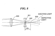
measurement is carried out as shown in FIG. 7A or 7B, or
else the detecting light must be diverged or converged
slightly using a lens (not shown) before being introduced
into the objective lens 500 so that the focal position
503 of the detecting light is shifted from the thermal
lens 501 as shown in FIG. 8; consequently, the working
efficiency of the user is poor.
It is an object of the present invention to provide
a microchemical system which dispenses with the optical
axis alignment and positioning of the focal point of the
detecting light and that of the exciting light, and is
capable of carrying out measurement with high sensitivity.
Disclosure of the Invention
To attain the above object, in a first aspect of the
present invention, there is provided a microchemical
system including a channel-formed plate-shaped member
that is equipped with a channel for containing a sample,
an exciting light source that irradiates exciting light
onto the sample via a converging lens, a detecting light
source that irradiates detecting light onto a thermal
lens formed within the sample by the irradiated exciting
light, via the converging lens, and detecting means for
detecting the irradiated detecting light via the formed
thermal lens, wherein the exciting light source and the
detecting light source are connected to the converging
lens via an optical fiber for propagating the exciting
light and the detecting light to the converging lens,
characterized in that the converging lens is fixed to the
channel-formed plate-shaped member, and the optical fiber
has a joint part capable of disconnecting the exciting
light source and the detecting light source from the
converging lens.
According to the first aspect of the present
invention, the optical fiber can be removably connected
using the joint part. Therefore, in the cases of the
channel having been stained, the channel-formed plate-shaped
member having been broken, and the optical fiber
having been broken, by replacing only the channel-formed
plate-shaped member to which the converging lens is fixed,
it is possible to perform fine and precise detection by
suppressing contamination of a liquid-borne sample and
reduce the running cost of the microchemical system.
Preferably, the joint part is a connector provided
midway of the optical fiber.
With this, the exciting light source and the
detecting light source can be easily connected to and
disconnected from the converging lens.
More preferably, the joint part is an FC connector.
With this, the exciting light source and the
detecting light source can be easily connected to and
disconnected from the converging lens. Further, the
connection can be made solid, and hence there is less
loss in the amount of the exciting light and the
detecting light propagating through the optical fiber.
Also preferably, the joint part is provided at an
end of the optical fiber via which the optical fiber is
connected to the converging lens.
With this, the construction of the joint part can be
made simple, whereby the microchemical system can be made
smaller in size.
More preferably, the joint part can be removably
attached to the converging lens.
With this, the construction of the joint part can be
made yet simpler, whereby the microchemical system can be
made yet smaller in size.
Further preferably, the joint part comprises an
annular member that can be fitted on the converging lens.
With this, the construction of the joint part can be
made yet simpler, whereby the microchemical system can be
made yet smaller in size.
Also, more preferably, the joint part can be
removably attached to the channel-formed plate-shaped
member.
With this, the construction of the joint part can be
made yet simpler, whereby the microchemical system can be
made yet smaller in size.
More preferably, the joint part comprises a first
annular member that can be fitted on the converging lens,
a second annular member that is fixed to the first
annular member in a manner coaxially accommodating the
first annular member therein and has an annular
protruding part formed on an inner peripheral surface
thereof, and a third annular member that is fixed to the
channel-formed plate-shaped member in a manner coaxially
accommodating the converging lens therein and has an
annular groove formed in an outer peripheral surface
thereof, for receiving the annular protruding part.
With this, the construction of the joint part can be
made yet simpler, whereby the microchemical system can be
made yet smaller in size.
Also, further preferably, the joint part comprises
pins erected at symmetrical locations with respect to the
converging lens, and an annular member that is coaxially
fixed to the optical fiber and has holes formed in an end
face thereof which is opposed to the channel-formed
plate-shaped member.
With this, the construction of the joint part can be
made yet simpler, whereby the microchemical system can be
made yet smaller in size.
Also preferably, the joint part enables connection
between the exciting light source and the detecting light
source, and the converging lens, in a manner such that
the optical axis of the converging lens and the optical
axis of the optical fiber are coaxial with each other.
With this, jigs for aligning the optical axes of the
exciting light and the detecting light are made
unnecessary, so that the construction of the joint part
can be made yet simpler, whereby the microchemical system
can be made yet smaller in size.
Also preferably, the frequency of the exciting light
is different from that of the detecting light.
With this, the focal positions of the exciting light
and the detecting light can be shifted from one another
without using any external optical systems, whereby the
microchemical system can be made yet smaller in size.
Also preferably, the converging lens has chromatic
aberration.
With this, the focal positions of the exciting light
and the detecting light can be positively shifted from
one another without using any external optical systems.
Also preferably, the converging lens is a gradient
index lens.
With this, the converging lens can be made smaller
in size, whereby the microchemical system can be made yet
smaller in size.
More preferably, the gradient index lens is a rod
lens having a cylindrical shape.
With this, the gradient index lens can be easily
held, and the optical axes of the optical fiber and that
of the gradient index lens can be easily aligned with
each other.
Also preferably, the channel-shaped plate-formed
member is made of a glass.
With this, the channel-shaped plate-formed member
has high resistance to chemicals, whereby the detecting
accuracy of the microchemical system can be improved.
Also preferably, the optical fiber propagates the
exciting light and the detecting light to the converging
lens with a single mode.
With this, the thermal lens formed by the exciting
light can be made smaller in size with little aberration,
and hence the detecting accuracy of the microchemical
system can be improved.
Also preferably, the detecting means is fixed on a
surface of the channel-formed plate-shaped member,
opposite to the converging lens fixed thereto, at a
location facing toward the channel of the channel-formed
plate-shaped member.
With this, the adjustment of the positions of the
converging lens and the detecting means are made
unnecessary, and moreover, since jigs for the adjustment
are unnecessary, the microchemical system can be made yet
smaller in size, and further the positioning of the
converging lens and the detecting means with respect to
the channel can be more reliably carried out whenever
analysis of a sample is to be carried out, whereby the
microchemical system can perform detection with enhanced
reproducibility and increased precision.
Brief Description of the Drawings
FIG. 1 is a view schematically showing the
construction of a microchemical system according to a
first embodiment of the present invention;
FIG. 2 is a view schematically showing the
construction of a microchemical system according to a
second embodiment of the present invention;
FIG. 3 is a view schematically showing the
construction of a microchemical system according to a
third embodiment of the present invention;
FIG. 4 is a view schematically showing the
construction of a microchemical system according to a
fourth embodiment of the present invention;
FIG. 5 is a view useful in explaining the principle
of a thermal lens;
FIGS. 6A and 6B are views useful in explaining the
formation position of a thermal lens and the focal
position of detecting light with respect to the direction
along the optical axis of exciting light, in which:
FIG. 6A shows a case in which an objective lens has
chromatic aberration; and
FIG. 6B shows a case in which the objective lens
does not have chromatic aberration;
FIGS. 7A and 7B are views useful in explaining the
formation position of a thermal lens and the focal
position of the detecting light with respect to the
optical axis of the exciting light, in which:
FIG. 7A shows a case in which the thermal lens is
formed closer to the objective lens than is the focal
position of the detecting light; and
FIG. 7B shows a case in which the thermal lens is
formed in a position further from the objective lens than
is the focal position of the detecting light; and
FIG. 8 is a view useful in explaining a method of
detecting changes in refractive index of a thermal lens
in a conventional photothermal conversion spectroscopic
analysis apparatus, and shows a case in which a concave
lens is put into an optical path so that detecting light
is made into divergent light, and hence the focal
position of the detecting light is made to be further
away than the focal position of exciting light.
Best Mode for Carrying Out the Invention
Hereafter, embodiments of the present invention will
now be described in detail with reference to the drawings.
FIG. 1 is a view schematically showing the
construction of a microchemical system according to a
first embodiment of the present invention.
In FIG. 1, the microchemical system 10 is comprised
of a channel-formed plate-shaped member 120 that has a
channel filled with a liquid-borne sample, a lens-equipped
optical fiber 100 that is disposed above the
channel-formed plate-shaped member 120 and has a lens
fitted at an end thereof, a light source unit 110 that is
connected to the lens-equipped optical fiber 100, for
irradiating, via the lens-quipped optical fiber 100,
exciting light onto the liquid-borne sample in the
channel of the channel-formed plate-shaped member 120,
and detecting light to a thermal lens formed in the
liquid-borne sample by the exciting light, and a
detecting device 130 that is disposed below the channel-formed
plate-shaped member 120, for detecting the
detecting light via the thermal lens formed in the sample
liquid in the channel of the channel-formed plate-shaped
member 120 by the exciting light.
The channel-formed plate-shaped member 120 is
comprised of an upper glass substrate 121, a middle glass
substrate 122, and a lower glass substrate 123, which are
sequentially stacked in the mentioned order from the
lens-equipped optical fiber 100 side, and joined together
by an adhesive.
The middle glass substrate 122 as the middle layer
of the channel-formed plate-shaped member 120 has a
channel 124 formed therein through which the sample
liquid is passed when the microchemical system 10 carries
out mixing, agitation, synthesis, separation, extraction,
detection or the like operation, on the sample liquid.
From the perspective of durability and chemical
resistance, the material of the upper glass substrate 121,
the middle substrate glass 122, and the lower glass
substrate 123 of the channel-formed plate-shaped member
120 is preferably a glass. In particular, considering
usage with biological samples such as cell samples, for
example in DNA analysis, a glass having high acid
resistance and alkali resistance is preferable,
specifically a borosilicate glass, a soda lime glass, an
aluminoborosilicate glass, a quartz glass or the like.
However, if the usage is limited accordingly, then a
channel-formed plate-shaped member 120 manufactured using
an organic material such as a plastic may be used instead.
Examples of adhesives that can be used to bond the
upper glass substrate 121, the middle glass substrate 122,
and the lower glass substrate 123 together include
organic adhesives, such as ultraviolet-curing type
adhesives, thermosetting type adhesives, two-liquid-curing
type acrylic adhesives, and epoxy adhesives, and
inorganic adhesives. Alternatively, the upper glass
substrate 121, the middle glass substrate 122, and the
lower glass substrate 123 may be fused together by heat
fusion.
The lens-equipped optical fiber 100 is comprised of
a gradient index rod lens 101 having a transparent
cylindrical shape, an optical fiber 102 connected to the
light source unit 110, for propagating the exciting light
and the detecting light with a single mode, an annular
member 105 fixed to an end of the optical fiber 102 via a
ferrule 104, for having the gradient index rod lens 101
fitted therein for fixing the same thereto, and an FC
connector 103 (joint part) disposed midway of the optical
fiber 102.
The ferrule 104 has a cylindrical shape with the
same outside diameter as that of the gradient index rod
lens 101 for making the outside diameter of the optical
fiber 102 be the same as that of the rod lens 101, and
has the optical fiber 102 inserted therethrough. The
ferrule 104 is placed on one surface of the gradient
index rod lens 101 and fixed to the gradient index rod
lens 101 by the annular member 105 as described above.
The optical fiber 102 may be fixed in intimate
contact with the gradient index rod lens 101 or may be
fixed via the ferrule 104 in a manner spaced from the
gradient index rod lens 101.
The gradient index rod lens 101 has an exit-side
surface thereof opposite to the ferrule 104 fixed to a
side surface of the upper glass substrate 121 opposite to
the middle glass substrate 122 such that a multiplex of
exciting light and detecting light exiting from the
gradient index rod lens 101 is perpendicularly incident
on the channel-formed plate-shaped member 120 to enter
the channel 124
The gradient index rod lens 101 may be fixed to the
upper glass substrate 121 directly using an adhesive, or
using a predetermined jig. Examples of the adhesives for
fixing the gradient index rod lens 101 to the upper glass
substrate 121 include organic adhesives, such as acrylic
adhesives including ultraviolet-curing type adhesives,
thermosetting adhesives, and two-liquid-curing type
adhesives, and epoxy adhesives, and inorganic adhesives.
The gradient index rod lens 101 is set such that the
focal position of the detecting light is shifted slightly
by an amount ΔL relative to the focal position of the
exciting light.
The value ΔL varies according to the thickness of
the liquid-borne sample on which measurements are to be
carried out. Assuming that a confocal length is
represented by Ic, when carrying out measurements on a
liquid-borne sample having a thickness lower than the
confocal length, it is most preferable for ΔL to be equal
to √3 x Ic.
The confocal length Ic (nm) is given by Ic = π
x(d/2)2/λ1. Here, d represents an airy disk and is given
by d = 1.22×λ1/NA, λ1 represents the wavelength (nm) of
the exciting light, and NA represents the numerical
aperture of the gradient index rod lens 101. In the case
of using the optical fiber 102, the numerical aperture of
the light exiting from the optical fiber 102 is small,
and hence it is necessary to use the numerical aperture
of the optical fiber 102 in the calculation of the
confocal length when using a rod lens having a large
numerical aperture.
The value ΔL represents the difference between the
focal position of the detecting light and the focal
position of the exciting light, and hence the result is
the same regardless of whether the focal distance of the
detecting light is longer or shorter than the focal
distance of the exciting light.
The gradient index rod lens 101 is configured such
that the refractive index changes continuously in a
radial direction from the position of a central axis
thereof that extends in a longitudinal direction thereof.
Such a rod lens is known as a converging light-transmitting
body configured such that the refractive
index n(r) at a position a distance r in the radial
direction from the central axis is given approximately by
the quadratic equation in r,
n(r) = n0 {1 - (g2/2) x r2},
wherein n0 represents the refractive index at the central
axis, and g represents a quadratic distribution constant.
If the length z0 of the gradient index rod lens 101
is chosen to be in a range of 0 < z0 < π/2g, then even
though the gradient index rod lens 101 has flat end faces,
the gradient index rod lens 101 will have the same image
formation characteristics as an ordinary convex lens;
when a parallel light beam is incident on the gradient
index rod lens 101, a focal point will be formed by the
parallel incident light beam at a position a distance so
from the exit-side end of the gradient index rod lens 101,
where
s0 = cot(gz0)/n0g.
Such a gradient index rod lens 101 may be
manufactured, for example, using the following method.
A rod is formed from a glass having as principal
components thereof 57 to 63 mol% of SiO2, 17 to 23 mol%
of B2O3, 5 to 17 mol% of Na2O, and 3 to 15 mol% of Tl2O,
and then the glass rod is treated in an ion exchange
medium such as potassium nitrate, thus carrying out ion
exchange between thallium ions and sodium ions in the
glass and potassium ions in the ion exchange medium, and
hence producing a refractive index distribution in the
glass rod in which the refractive index decreases
continuously from the central axis of the glass rod
radially outward.
Because the surface of the gradient index rod lens
101 is flat, it can be easily attached to the end of the
optical fiber 102, and moreover the optical axis of the
gradient index rod lens 101 and the optical axis of the
optical fiber 102 can easily be aligned with one another.
The gradient index rod lens 101 is connected to one
end of the optical fiber 102 that propagates the exciting
light and the detecting light; as a result, there is no
need to adjust the optical axes of the exciting light and
the detecting light and the optical axis of the gradient
index rod lens 101 each time measurement is carried out,
and moreover jigs for aligning the optical axes and a
predetermined sturdy surface plate are unnecessary, and
hence the working efficiency of a user can be improved,
and moreover the microchemical system can be made smaller
in size.
The FC connector 103 is comprised of FC plugs 106
and 107, and an adapter 108 having the FC plugs 106 and
107 removably connected thereto. The FC plugs 106 and
107 are each comprised of a cylindrical ferrule having
the optical fiber 102 connected along the central axis
thereof and having a diameter of 2.5 mm, and a nut
coaxially and rotatably receiving the ferrule therein.
The adapter 108 is comprised of a cylindrical flange, and
two cylindrical protruding parts coaxially and
perpendicularly attached to opposite sides of the flange.
The two cylindrical protruding parts have a thread formed
on the outer periphery thereof in association with the
nuts of the FC plugs 106 and 107. Further, the flange
and the two protruding parts are formed therethrough with
a through hole coaxial with the flange, for receiving the
ferrules of the FC plugs 106 and 107 therein. Further,
the FC plugs 106 and 107 and the adapter 108 have a
rotation-inhibiting means attached thereto for inhibiting
rotation of the ferrules inserted into the through hole
of the adapter 108, when the associated nuts are fastened.
The ferrules of the FC plugs 106 and 107 are
inserted into the through hole of the adapter 108, and
the nuts of the FC plugs 106 and 107 are screwed onto the
thread of the adapter 108, whereby the FC plugs 106 and
107 are fastened to the adapter 108 such that the opposed
ends of the FC plugs 106 and 107 are brought into contact
with each other to establish connection of the optical
fibers 102.
By fixing the FC plugs 106 and 107 via the adapter
108 as described above, it is possible to maintain
connection of the optical fibers via the ferrules even in
a vibrating environment. Further, since the FC plugs 106
and 107 are connected to the adapter 108 using the nuts
as describe above, the FC plugs 106 and 107 can be easily
attached to and removed from the adapter 108. The
durability of the FC connector 103 is guaranteed to 1,000
times of attachment and removal thereof.
The insertion loss of the amounts of the exciting
light and the detecting light propagating through the
optical fiber 102 caused by provision of the FC connector
103 midway of the optical fiber 102 is as low as 0.3 dB,
so that the optical fiber 102 is capable of propagating
the exciting light and the detecting light therethrough
by way of the FC connector 103 almost without any loss.
When detecting a very small amount of liquid-borne
sample using the photothermal conversion spectroscopic
analysis method, it is preferable to narrow down the
exciting light as much as possible to thereby increase
energy thereof used for photothermal conversion, and at
the same time form a thermal lens generated by the
exciting light such that the thermal lens has little
aberration. It is preferable for the optical fiber 102
to propagate the exciting light and the detecting light
with a single mode.
Since the optical fiber 102 is used with a single
mode, and the light exiting from the optical fiber 102
will always have a Gaussian distribution, the focal point
of the exciting light will be small in size. Moreover,
in the case that the thermal lens produced by the
exciting light is small in size, to make the amount of
the detecting light that passes through the thermal lens
be as high as possible, it is preferable to also narrow
down the detecting light as much as possible. From this
standpoint as well, it is preferable for the optical
fiber 102 to propagate the exciting light and the
detecting light with a single mode.
Any type of optical fiber can be used as the optical
fiber 102 insofar as it can transmit the exciting light
and the detecting light. However, in the case that a
multi-mode optical fiber is used, the exiting light will
not have a Gaussian distribution, and moreover the
pattern of the exiting light will vary according to
various conditions such as the state of curvature of the
optical fiber 102, and hence it will not necessarily be
possible to obtain stable exiting light. Carrying out
measurement on a very small amount of a liquid-borne
sample will thus be difficult, and moreover there may be
a lack of stability in the measured value. It is thus
preferable for the optical fiber 102 to be a single-mode
optical fiber as described above.
If the leading end of the optical fiber were
processed into a spherical shape or the like to form a
lens, then it would be possible to narrow down the
exciting light and the detecting light without installing
a separate lens at the leading end of the optical fiber.
However, in this case, there would be hardly any
chromatic aberration, and hence the focal positions of
the exciting light and the detecting light would be
almost the same as one another. There would thus be a
problem of the thermal lens signal being hardly
detectable. Moreover, aberration would be high for the
lens formed by processing the leading end of the optical
fiber, and hence there would also be a problem of the
focal points of the exciting light and the detecting
light being large. In the first embodiment of the
present invention, a gradient index rod lens 101 is thus
installed at the leading end of the optical fiber 102.
The light source unit 110 is comprised of an
exciting light source 111 that outputs the exciting light,
a modulator 112 that is connected to the exciting light
source 111 and modulates the exciting light output
therefrom, a detecting light source 113 that outputs the
detecting light, and a two-wavelength multiplexing device
115 that is connected to the exciting light source 111
and the detecting light source 113 via respective optical
fibers 114, and at the same time connected to the optical
fiber 102 of the lens-equipped optical fiber 100, for
multiplexing the exciting light output from the exciting
light source 111 and the detecting light output from the
detecting light source 113 to cause the multiplexed light
of the exciting light and the detecting light to enter
the optical fiber 102.
In the light source unit 110, a dichroic mirror may
be used in place of the two-wavelength multiplexing
device 115, to multiplex the exciting light output from
the exciting light source 111 and the detecting light
output from the detecting light source 113 to cause the
multiplexed light of the exciting light and the detecting
light to enter the optical fiber 102.
The detecting device 130 is comprised of a
wavelength filter 131 provided in a position facing
toward the channel 124 of the channel-formed plate-shaped
member 120 and opposite to the optical fiber 100, for
separating the multiplexed exciting light and detecting
light and selectively allows only the detecting light to
pass therethrough, a photoelectric converter 132 provided
in a position under the wavelength filter 131 and facing
toward the channel 124, for detecting the detecting light,
and a computer 134 connected to the photoelectric
converter 132 via a lock-in amplifier 133.
In the detecting device 130, a predetermined member
having a pinhole formed therein in order for only part of
the detecting light to be selectively transmitted may
also be provided in a position upstream of the
photoelectric converter 132 in the optical path of the
detecting light.
Signals obtained by the photoelectric converter 132
are sent to the lock-in amplifier 133 for carrying out
synchronization with the modulator 112 that modulates the
exciting light, and are then analyzed by the computer 134.
According to the microchemical system shown in FIG.
1, it is provided with the FC connector 103 equipped with
the FC plugs 106 and 107 that can be removably attached
midway of the optical fiber 102, and hence it is possible
to remove the channel-formed plate-shaped member 120 to
which the gradient index rod lens 101 is fixed from the
microchemical system 10 by separating the FC plugs 106
and 107 joined together. As a result, in the cases of
the inside of the channel 124 of the channel-formed
plate-shaped member 120 having been stained, the channel-formed
plate-shaped member 120 having been broken, and
the gradient index rod lens 101 having been broken, it is
only required to replace the channel-formed plate-shaped
member 120 alone to which the gradient index rod lens 101
is fixed, and hence it is possible to reduce the running
cost of the microchemical system 10 and perform fine and
precise measurement by suppressing contamination of the
liquid-borne sample caused by replacing the channel-formed
plate-shaped member 120 to which the gradient
index rod lens 101 is fixed each time a liquid-borne
sample for detection is changed, as much as possible.
According to the microchemical system shown in FIG.
1, the gradient index rod lens 101 is fixed to the
leading end of the optical fiber 102 that propagates the
exciting light and the detecting light and at the same to
the surface of the channel-formed plate-shaped member 120
in a manner facing toward the channel 124. As a result,
it is not necessary to adjust the optical axes of the
exciting light and the detecting light propagating
through the optical fiber 102 and that of the gradient
index rod lens 101, and in addition, it is not necessary
to adjust the positions of the gradient index rod lens
101 and the channel 123. Therefore, it is possible to
dispense with predetermined jigs and a predetermined
sturdy surface plate for alignment of the optical axes of
the exciting light and the detecting light and that of
the gradient index rod lens 101 or positioning of the
gradient index rod lens 101 and the channel 124 relative
to each other, so that it is possible to improve the
working efficiency of the user and reduce the size of the
microchemical system.
According to the microchemical system 10 shown in
FIG. 1, the focal position of the exciting light that has
passed through the gradient index rod lens 101 must be in
the channel 204 of the channel-formed plate-shaped member
120. The gradient index rod lens 101 is fixed to the
upper glass substrate 121 of the channel-formed plate-shaped
member 120 in contact therewith,' so that the focal
length of the exciting light exiting from the gradient
index rod lens 101 can be adjusted through the thickness
of the upper glass substrate 121. Further, in the case
that the thickness of the upper glass substrate 121 is
insufficient, a spacer may be inserted between the
gradient index rod lens 101 and the upper glass substrate
121 to fix the gradient index rod lens 101 and the upper
glass substrate 121 to each other with the spacer
interposed therein whereby the focal length can be
adjusted. In the case that the focal position of the
exciting light is fixed in advance to be in the channel
124 of the channel-formed plate-shaped member 120 in this
way, subsequent adjustment of the focal distance becomes
unnecessary, and hence the microchemical system can be
made yet smaller in size.
Although in the first embodiment of the present
invention, the FC connector 103 is provided midway of the
optical fiber 102, this is not limitative, but in place
of the FC connector 103, there may be used a D-4 style
connector, a ST-style connector, an FDDI-MIC connector,
and an ESCON connector.
FIG. 2 is a view schematically showing the
construction of a microchemical system according to a
second embodiment of the present invention.
In FIG. 2, the microchemical system 20 according to
the second embodiment basically has the same construction
as that of the microchemical system 10 shown in FIG. 1.
Therefore, identical components are represented by the
same reference numerals, and duplicate description of
these components is omitted. The following description
will be given of different components.
In FIG. 2, the microchemical system 20 is
distinguished from the microchemical system 10 shown in
FIG. 1 in that the lens-equipped optical fiber 100 is
replaced by a stopper-equipped optical fiber 200, and the
channel-formed plate-shaped member 120 is replaced by a
channel-formed plate-shaped member 210.
The channel-formed plate-shaped member 210 is
comprised of the channel-formed plate-shaped member 120
appearing in FIG. 1, and a gradient index rod lens 211
having the same shape, the same size, and the same
characteristics as those of the gradient index rod lens
101 appearing in FIG. 1. The gradient index rod lens 211
has an exit-side surface thereof fixed to the surface of
the upper glass substrate 121 opposite to the middle
glass substrate 122 such that the exciting light and the
detecting light exiting from the gradient index rod lens
are perpendicularly incident on each of the upper glass
substrate 121, the middle glass substrate 122, and the
lower glass substrate 123 to enter the channel 124.
The stopper-equipped optical fiber 200 is comprised
of an optical fiber 203 connected to the two-wavelength
multiplexing device 115, and an annular member 201 (joint
part) fixed to the leading end of the optical fiber 203
via a ferrule.202, for having the gradient index rod lens
211 fitted therein. The optical fiber 203 has the same
characteristics as those of the optical fiber 102 of the
microchemical system 10 shown in FIG. 1.
The annular member 201 is formed such that the inner
diameter of a cross-section thereof has approximately the
same size as the diameter of a cross-section of the
gradient index rod lens 211, for being fitted on the
gradient index lens 211, whereby the gradient index rod
lens 211 can be removably attached thereto by fitting the
same in the annular member 201.
According to the microchemical system 20 shown in
FIG. 2, by fitting the annular member 201 of the stopper-equipped
optical fiber 200 onto the gradient index rod
lens 211 of the channel-formed plate-shaped member 210,
the optical axes of the exciting light and detecting
light that propagate through the two optical fiber 203
and the optical axis of the gradient index rod lens 211
can accurately aligned with each other.
According to the microchemical system 20 shown in
FIG. 2, the annular member 201 of the stopper-equipped
optical fiber 200 can be removably fitted on the gradient
index rod lens 211 of the channel-formed plate-shaped
member 210. Therefore, in the cases of the inside of the
channel 124 of the channel-formed plate-shaped member 210
having been stained, and the channel-formed plate-shaped
member 210 having been broken, it is only required to
replace the channel-formed plate-shaped member 210 alone
to which the gradient index rod lens 211 is fixed, and
further it is possible to perform fine and precise
measurement by suppressing contamination of the liquid-borne
sample caused by replacing the channel-formed
plate-shaped member 210 to which the gradient index rod
lens 211 is fixed each time a liquid-borne sample for
detection is changed, as much as possible.
According to the microchemical system 20 shown in
FIG. 2, the gradient index rod lens 211 is fixed to the
surface of the upper glass substrate 121 of the channel-formed
plate-shaped member 210 in a manner facing toward
the channel 124. As a result, it is not necessary to
adjust the positions of the gradient index rod lens 211
and the channel 124, and hence it is possible to dispense
with predetermined jigs and a predetermined sturdy
surface plate for positioning of the gradient index rod
lens 211 and the channel 124 relative to each other, so
that it is possible to improve the working efficiency of
the user and reduce the size of the microchemical system.
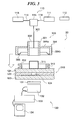
FIG. 3 is a view schematically showing the
construction of a microchemical system according to a
third embodiment of the present invention.
In FIG. 3, the microchemical system 30 according to
the third embodiment basically has the same construction
as that of the microchemical system 10 shown in FIG. 1.
Therefore, identical components are represented by the
same reference numerals, and duplicate description of
these components is omitted. The following description
will be given of different components.
In FIG. 3, the microchemical system 30 is
distinguished from the microchemical system 10 shown in
FIG. 1 in that the lens-equipped optical fiber 100 is
replaced by a stopper-equipped optical fiber 300, and the
channel-formed plate-shaped member 120 is replaced by a
channel-formed plate-shaped member 310.
The channel-formed plate-shaped member 310 is
comprised of the channel-formed plate-shaped member 120
appearing in FIG. 1, a gradient index rod lens 311 having
the same shape, the same size, and the same
characteristics as those of the gradient index rod lens
101 appearing in FIG. 1, and an annular member 312(third
annular member).
The gradient index rod lens 311 has an exit-side
surface thereof fixed to the surface of the upper glass
substrate 121 opposite to the middle glass substrate 122
such that the exciting light and the detecting light
exiting from the gradient index rod lens 311 are
perpendicularly incident on each of the upper glass
substrate 121, the middle glass substrate 122, and the
lower glass substrate 123 to enter the channel 124.
The stopper-equipped optical fiber 300 is comprised
of an optical fiber 303 connected to the two-wavelength
multiplexing device 115, and an annular member 301 (first
annular member) fixed to the leading end of the optical
fiber 303 via a ferrule 302, for having the gradient
index rod lens 311 fitted therein, and a stopper 304
(second annular member) fitted on the annular member 301.
The stopper 304 is comprised of a collar 304a fixed to
the annular member 301, and an annular part 304b formed
integrally with the periphery of the collar 304a. On an
inner peripheral surface of the annular part 304b, there
is provided a lip-shaped annular protruding part 305 made
of a resilient member, such as rubber.
The annular member 312 is fixed to the upper glass
substrate 121 in a manner receiving the gradient index
rod lens 311 therein, and has an annular groove 313
formed in the outer peripheral surface thereof, for
receiving the annular protruding part 305.
The annular member 301 has a hollow cylindrical
shape, and is formed such that the inner diameter of a
cross-section thereof has approximately the same size as
the diameter of a cross-section of the gradient index rod
lens 311, for being fitted on the gradient index lens 311,
whereby the gradient index rod lens 311 can be removably
attached thereto by fitting the same in the annular
member 301.
The stopper-equipped optical fiber 300 is removably
integrated with the channel-formed plate-shaped member
310 by having the annular protruding part 305 of the
stopper 304 received in the annular groove 313 of the
annular member 312 to supportingly embrace the annular
groove 313 by the annular protruding part 305, when the
annular member 301 is fitted on the gradient index rod
lens 311.
According to the microchemical system 30 shown in
FIG. 3, when the annular member 301 is fitted on the
gradient index rod lens 311, the stopper 3304 is fitted
on the annular member 312 such that the annular
protruding part 305 of the stopper 304 is received in the
annular groove 313 of the annular member 312 to
supportingly embrace the annular groove 313. Therefore,
by merely fitting the annular member 301 of the stopper-equipped
optical fiber 300 on the gradient index rod lens
311 of the channel-formed plate-shaped member 310, it is
possible to precisely align the optical axes of the
exciting light and the detecting light propagating
through the optical fiber 303 with the optical axis of
the gradient index rod lens 311, and stably hold the
positions of these optical axes for precise measurement.
According to the microchemical system 30 shown in
FIG. 3, the annular member 301 of the optical fiber 300
can be removably fitted on the gradient index rod lens
311 of the channel-formed plate-shaped member 310.
Therefore, in the cases of the inside of the channel 124
of the channel-formed plate-shaped member 310 having been
stained, and the channel-formed plate-shaped member 310
having been broken, it is only required to replace the
channel-formed plate-shaped member 310 alone to which the
gradient index rod lens 311 is fixed, and further it is
possible to perform fine and precise measurement by
suppressing contamination of the liquid-borne sample
caused by replacing the channel-formed plate-shaped
member 310 to which the gradient index rod lens 311 is
fixed each time a liquid-borne sample is changed, as much
as possible.
According to the microchemical system 30 shown in
FIG. 3, the gradient index rod lens 311 is fixed to the
surface of the upper glass substrate 121 of the channel-formed
plate-shaped member 310 in a manner facing toward
the channel 124. As a result, it is not necessary to
adjust the positions of the gradient index rod lens 311
and the channel 124, and hence it is possible to dispense
with predetermined jigs and a predetermined sturdy
surface plate for positioning of the gradient index rod
lens 211 and the channel 124 relative to each other, so
that it is possible to improve the working efficiency of
the user and reduce the size of the microchemical system.
In the microchemical system 30 shown in FIG. 3, the
shapes of the stopper 304 and the annular member 312 are
not limited to those described above.
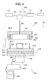
FIG. 4 is a view schematically showing the
construction of a microchemical system according to a
fourth embodiment of the present invention.
In FIG. 4, the microchemical system 40 according to
the fourth embodiment basically has the same construction
as that of the microchemical system 10 shown in FIG. 1.
Therefore, identical components are represented by the
same reference numerals, and duplicate description of
these components is omitted. The following description
will be given of different components.
In FIG. 4, the microchemical system 40 is
distinguished from the microchemical system 10 shown in
FIG. 1 in that the lens-equipped optical fiber 100 is
replaced by a stopper-equipped optical fiber 400, the
channel-formed plate-shaped member 120 by a channel-formed
plate-shaped member 410, and the detecting device
130 by a detecting device 420.
The channel-formed plate-shaped member 410 is
comprised of the channel-formed plate-shaped member 120
appearing in FIG. 1, a gradient index rod lens 411 having
the same shape, the same size, and the same
characteristics as those of the gradient index rod lens
101 appearing in FIG. 1, and two pins 412.
The gradient index rod lens 411 has an exit-side
surface thereof fixed to the surface 121a of the upper
glass substrate 121 opposite to the middle glass
substrate 122 such that the exciting light and the
detecting light exiting from the gradient index rod lens
411 are perpendicularly incident on each of the upper
glass substrate 121, the middle glass substrate 122, and
the lower glass substrate 123 to enter the channel 124.
The detecting device 420 is disposed under the
channel-formed plate-shaped member 410, and is comprised
of a wavelength filter 421 identical to the wavelength
filter 131 of the microchemical system 10 shown in FIG. 1,
a photoelectric converter 422 identical to the
photoelectric converter 132 of the microchemical system
10 shown in FIG. 1, and a computer 424 which is identical
to the computer 134 of the microchemical system 10 shown
in FIG. 1 and is connected to the photoelectric converter
422 via a lock-in amplifier 423 identical to the lock-in
amplifier 133 of the microchemical system 10 shown in FIG.
1.
The wavelength filter 421 has one surface thereof
attached to the surface of the lower glass substrate 123
in a position facing toward the channel 124 of the
channel-formed plate-shaped member 410, and the
photoelectric converter 422 has one surface thereof
attached to the other surface of the wavelength filter
421 in a position facing toward the channel 124.
The pins 412 are erected at symmetrical locations
with respect to the gradient index rod lens 411.
The stopper-equipped optical fiber 400 is comprised
of an optical fiber 405 connected to the two-wavelength
multiplexing device 115, and a stopper 401 (annular
member) fixed to the leading end of the optical fiber 405.
The stopper 401 is comprised of a collar 401a fixed to
the optical fiber 405, and an annular part 401b formed
integrally with the periphery of the collar 401a. The
annular part 401b has two holes 402 formed in a surface
thereof opposed to the upper glass substrate 121, for
receiving the two pins 412 therein. Further, the annular
part 401b has through holes 403 formed in the outer
peripheral surface thereof such that the through holes
403 extend to the respective holes 402 perpendicularly
thereto toward the longitudinal central axis of the
stopper 401. Check pins 404 which can be fitted in the
through holes 403 are removably attached thereto. The
optical fiber 405 has the same characteristics as those
of the optical fiber 102 of the microchemical system 10
shown in FIG. 1.
In the stopper-equipped optical fiber 400 and the
channel-formed plate-shaped member 410, the pins 412 are
received in the holes 402 of the stopper 401, whereby the
stopper 401 and the channel-formed plate-shaped member
410 are integrally joined with each other to connect the
optical fiber 405 and the gradient index rod lens 411
such that their optical axes are aligned with each other.
Further, when the stopper 401 and the channel-formed
plate-shaped member 410 are thus integrated with each
other, the pins 412 may be fixed to the holes 402 by
fitting the check pins 404 in the through holes 403
formed in the outer peripheral surface of the annular
part 401b of the stopper 401. The stopper 401 and the
channel-formed plate-shaped member 410 can be thus
integrally fixed to each other such that the stopper 401
and the channel-formed plate-shaped member 410 cannot be
separated from each other unless attempted intentionally.
The optical axis of the optical fiber 405 and the
optical axis of the gradient index rod lens 411 are made
more precisely aligned with each other by forming the
holes 402 of the stopper 401 and the pins 412 such that
they have as equal diameters as possible. Further, they
can be more precisely aligned with each..other by
increasing the number of holes 402 and the number of
associated pins 412.
According to the microchemical system 40 shown in
FIG. 4, there is not used any component in direct contact
with the gradient index rod lens 411, so that there is
less possibility of the gradient index rod lens 411 being
flawed or chipped, to thereby prevent such a flaw or chip
from affecting the lens characteristics of the gradient
index rod lens 411. As a result, it is possible to
increase the number of times of use of the channel-formed
plate-shaped member 410 to which is fixed the gradient
index rod lens 411, and this makes it possible to reduce
the running cost of the microchemical system 40 and
perform precise analysis enhanced in reproducibility.
According to the microchemical system 40 shown in
FIG. 4, the photoelectrical converter 422 of the
detecting device 420 is fixed to the channel-formed
plate-shaped member 410. As a result, it is not
necessary to adjust the position of the photoelectrical
converter 422 each time detection is performed, and hence
it is possible to improve the working efficiency of the
user. Since predetermined jigs for adjustment of the
position can be dispensed with, it is possible to reduce
the size of the microchemical system. Further, since the
position of the photoelectrical converter 422 does.not
change each time detection is performed, it is possible
to perform precise analysis enhanced in reproducibility.
The shapes of the stopper 401, the holes 402, and
the pins 412 used in the microchemical system 40 shown in
FIG. 4 are not limited to those described above.
Although the wavelength filter 131 and the
photoelectrical converter 132 used in the microchemical
system 10 shown in FIG. 1, the microchemical system 20
shown in FIG. 2, and the microchemical system 30 shown in
FIG. 3 are not fixed to the lower glass substrate 123 of
the respective channel-formed plate-shaped members 120,
210, and 310, this is not limitative, but they may be
fixed to the lower glass substrate 123 of the respective
channel-formed plate-shaped members 120, 210, and 310.
Although the upper glass substrate 121, the middle
glass substrate 122, and the lower glass substrate 123 of
the channel-formed plate-shaped member 120 of the
microchemical system 10 shown in FIG. 1, the channel-formed
plate-shaped member 210 of the microchemical
system 20 shown in FIG. 2, the channel-formed plate-shaped
member 310 of the microchemical system 30 shown in
FIG. 3, and the channel-formed plate-shaped member 410 of
the microchemical system 40 shown in FIG. 4 are made of a
glass, the present invention is not limited to this
specific example.
Industrial Applicability
As described in detail above, according to the
microchemical system according of the present invention,
the optical fiber can be removably connected using a
joint part. Therefore, in the cases of the channel
having been stained, the channel-formed plate-shaped
member having been broken, and the optical fiber having
been broken, by replacing only the channel-formed plate-shaped
member to which the converging lens is fixed, it
is possible to perform fine and precise detection by
suppressing contamination of the liquid-borne sample and
reduce the running cost of the microchemical system.
According to the microchemical system of the present
invention, the joint part is a connector provided midway
of the optical fiber. As a result, the exciting light
source and the detecting light source can be easily
connected to and disconnected from the converging lens.
According to the microchemical system of the present
invention, the joint part is an FC connector provided
midway of the optical fiber. As a result, the exciting
light source and the detecting light source can be easily
connected to and disconnected from the converging lens.
Further, the connection can be made solid, and hence
there is less loss in the amount of the exciting light
and the detecting light propagating through the optical
fiber.
According to the microchemical system of the present
invention, the joint part is provided at an end of the
optical fiber opposed to the converging lens via which
the optical fiber is connected to the converging lens.
As a result, the construction of the joint part can be
made simple, whereby the microchemical system can be made
smaller in size.
According to the microchemical system of the present
invention, the joint part can be removably attached to
the converging lens. As a result, the construction of
the joint part can be made yet simpler, whereby the
microchemical system can be made yet smaller in size.
According to the microchemical system of the present
invention, the joint part comprises an annular member
that can be fitted on the converging lens. As a result,
the construction of the joint part can be made yet
simpler, whereby the microchemical system can be made yet
smaller in size.
According to the microchemical system of the present
invention, the joint part can be removably attached to
the channel-formed plate-shaped member. As a result, the
construction of the joint part can be made yet simpler,
whereby the microchemical system can be made yet smaller
in size.
According to the microchemical system of the present
invention, the joint part is configured such that the
first annular member can be fitted on the converging lens,
and the second annular member fixed to the first annular
member in a manner coaxially accommodating the first
annular member therein has the annular protruding part
formed on the inner peripheral surface thereof, for being
fitted in the annular groove formed in the outer
peripheral surface of the third annular member fixed to
the channel-formed plate-shaped member in a manner
coaxially accommodating the converging lens therein. As
a result, the construction of the joint part can be made
yet simpler, whereby the microchemical system can be made
yet smaller in size.
According to the microchemical system of the present
invention, the joint part is configured such that the
annular member has holes formed in the end face thereof
opposed to the channel-formed plate-shaped member, for
receiving the pins erected at symmetric locations with
respect to the converging lens. As a result, the
construction of the joint part can be made yet simpler,
whereby the microchemical system can be made yet smaller
in size.
According to the microchemical system of the present
invention, the joint part enables connection between the
exciting light source and the detecting light source, and
the converging lens, in a manner such that the optical
axis of the converging lens and the optical axis of the
optical fiber are coaxial with each other. As a result,
jigs for aligning the optical axes of the exciting light
and the detecting light are made unnecessary, so that the
construction of the joint part can be made yet simpler,
whereby the microchemical system can be made yet smaller
in size.
According to the microchemical system of the present
invention, the frequency of the exciting light is
different from that of the detecting light, and the
converging lens has chromatic aberration. As a result,
the focal positions of the exciting light and the
detecting light can be shifted from one another without
using any external optical systems, whereby the
microchemical system can be made yet smaller in size.
According to the microchemical system of the present
invention, the converging lens has chromatic aberration.
As a result, the focal positions of the exciting light
and the detecting light can be positively shifted from
one another without using any external optical systems.
According to the microchemical system of the present
invention, the converging lens is a gradient index lens.
As a result, the converging lens can be made smaller in
size, whereby the microchemical system can be made yet
smaller in size.
According to the microchemical system of the present
invention, the gradient index lens is a rod lens having a
cylindrical shape. As a result, the gradient index lens
can be easily held, and the optical axes of the optical
fiber and the gradient index lens can be easily aligned
with each other.
According to the microchemical system of the present
invention, the channel-shaped plate-formed member is made
of a glass. As a result, the channel-shaped plate-formed
member has high resistance to chemicals, whereby the
detecting accuracy of the microchemical system can be
improved.
According to the microchemical system of the present
invention, the optical fiber propagates the exciting
light and the detecting light with a single mode. As a
result, the thermal lens formed by the exciting light can
be made smaller in size with little aberration, and hence
more precise detection can be carried out.
According to the microchemical system of the present
invention, the detecting means is fixed on a surface of
the channel-formed plate-shaped member, opposite to the
converging lens fixed thereto, in a position facing
toward the channel of the channel-formed plate-shaped
member. As a result, the adjustment of the positions of
the converging lens and the detecting means can be made
unnecessary, and moreover, since jigs for the adjustment
are unnecessary, the microchemical system can be made yet
smaller in size, and further the positioning of the
converging lens and the detecting means with respect to
the channel can be more reliably carried out each time
analysis of a sample is carried out, whereby the
microchemical system can perform detection with enhanced
reproducibility and increased precision.