EP1548344A1 - Opening and closing valve - Google Patents
Opening and closing valve Download PDFInfo
- Publication number
- EP1548344A1 EP1548344A1 EP03791442A EP03791442A EP1548344A1 EP 1548344 A1 EP1548344 A1 EP 1548344A1 EP 03791442 A EP03791442 A EP 03791442A EP 03791442 A EP03791442 A EP 03791442A EP 1548344 A1 EP1548344 A1 EP 1548344A1
- Authority
- EP
- European Patent Office
- Prior art keywords
- valve
- pilot
- water
- push rod
- switching valve
- Prior art date
- Legal status (The legal status is an assumption and is not a legal conclusion. Google has not performed a legal analysis and makes no representation as to the accuracy of the status listed.)
- Granted
Links
- 238000003825 pressing Methods 0.000 claims abstract description 8
- 230000004044 response Effects 0.000 claims abstract description 8
- XLYOFNOQVPJJNP-UHFFFAOYSA-N water Substances O XLYOFNOQVPJJNP-UHFFFAOYSA-N 0.000 claims description 88
- 230000007246 mechanism Effects 0.000 claims description 26
- 238000007599 discharging Methods 0.000 claims description 12
- 229910001220 stainless steel Inorganic materials 0.000 claims description 3
- 239000010935 stainless steel Substances 0.000 claims description 3
- 238000006073 displacement reaction Methods 0.000 description 13
- 238000007789 sealing Methods 0.000 description 12
- 238000010586 diagram Methods 0.000 description 8
- 238000000034 method Methods 0.000 description 7
- 230000008569 process Effects 0.000 description 7
- 230000000712 assembly Effects 0.000 description 6
- 238000000429 assembly Methods 0.000 description 6
- 230000002093 peripheral effect Effects 0.000 description 6
- 230000005489 elastic deformation Effects 0.000 description 3
- 238000012423 maintenance Methods 0.000 description 3
- 230000004048 modification Effects 0.000 description 3
- 238000012986 modification Methods 0.000 description 3
- 230000002159 abnormal effect Effects 0.000 description 2
- 230000007797 corrosion Effects 0.000 description 2
- 238000005260 corrosion Methods 0.000 description 2
- 230000007547 defect Effects 0.000 description 2
- 230000006866 deterioration Effects 0.000 description 2
- 238000003780 insertion Methods 0.000 description 2
- 230000037431 insertion Effects 0.000 description 2
- 239000008399 tap water Substances 0.000 description 2
- 235000020679 tap water Nutrition 0.000 description 2
- 239000004743 Polypropylene Substances 0.000 description 1
- 238000004140 cleaning Methods 0.000 description 1
- 238000004891 communication Methods 0.000 description 1
- 239000000428 dust Substances 0.000 description 1
- 239000012530 fluid Substances 0.000 description 1
- 230000006872 improvement Effects 0.000 description 1
- 238000009434 installation Methods 0.000 description 1
- 239000000463 material Substances 0.000 description 1
- 238000012856 packing Methods 0.000 description 1
- -1 polypropylene Polymers 0.000 description 1
- 229920001155 polypropylene Polymers 0.000 description 1
- 230000009467 reduction Effects 0.000 description 1
- 239000011347 resin Substances 0.000 description 1
- 229920005989 resin Polymers 0.000 description 1
- 230000001052 transient effect Effects 0.000 description 1
Images






Classifications
-
- F—MECHANICAL ENGINEERING; LIGHTING; HEATING; WEAPONS; BLASTING
- F16—ENGINEERING ELEMENTS AND UNITS; GENERAL MEASURES FOR PRODUCING AND MAINTAINING EFFECTIVE FUNCTIONING OF MACHINES OR INSTALLATIONS; THERMAL INSULATION IN GENERAL
- F16K—VALVES; TAPS; COCKS; ACTUATING-FLOATS; DEVICES FOR VENTING OR AERATING
- F16K21/00—Fluid-delivery valves, e.g. self-closing valves
- F16K21/04—Self-closing valves, i.e. closing automatically after operation
- F16K21/06—Self-closing valves, i.e. closing automatically after operation in which the closing movement, either retarded or not, starts immediately after opening
- F16K21/12—Self-closing valves, i.e. closing automatically after operation in which the closing movement, either retarded or not, starts immediately after opening with hydraulically-operated opening means; with arrangements for pressure relief before opening
-
- E—FIXED CONSTRUCTIONS
- E03—WATER SUPPLY; SEWERAGE
- E03C—DOMESTIC PLUMBING INSTALLATIONS FOR FRESH WATER OR WASTE WATER; SINKS
- E03C1/00—Domestic plumbing installations for fresh water or waste water; Sinks
- E03C1/02—Plumbing installations for fresh water
- E03C1/04—Water-basin installations specially adapted to wash-basins or baths
-
- F—MECHANICAL ENGINEERING; LIGHTING; HEATING; WEAPONS; BLASTING
- F16—ENGINEERING ELEMENTS AND UNITS; GENERAL MEASURES FOR PRODUCING AND MAINTAINING EFFECTIVE FUNCTIONING OF MACHINES OR INSTALLATIONS; THERMAL INSULATION IN GENERAL
- F16K—VALVES; TAPS; COCKS; ACTUATING-FLOATS; DEVICES FOR VENTING OR AERATING
- F16K11/00—Multiple-way valves, e.g. mixing valves; Pipe fittings incorporating such valves
-
- F—MECHANICAL ENGINEERING; LIGHTING; HEATING; WEAPONS; BLASTING
- F16—ENGINEERING ELEMENTS AND UNITS; GENERAL MEASURES FOR PRODUCING AND MAINTAINING EFFECTIVE FUNCTIONING OF MACHINES OR INSTALLATIONS; THERMAL INSULATION IN GENERAL
- F16K—VALVES; TAPS; COCKS; ACTUATING-FLOATS; DEVICES FOR VENTING OR AERATING
- F16K31/00—Actuating devices; Operating means; Releasing devices
- F16K31/12—Actuating devices; Operating means; Releasing devices actuated by fluid
- F16K31/126—Actuating devices; Operating means; Releasing devices actuated by fluid the fluid acting on a diaphragm, bellows, or the like
- F16K31/128—Actuating devices; Operating means; Releasing devices actuated by fluid the fluid acting on a diaphragm, bellows, or the like servo actuated
-
- F—MECHANICAL ENGINEERING; LIGHTING; HEATING; WEAPONS; BLASTING
- F16—ENGINEERING ELEMENTS AND UNITS; GENERAL MEASURES FOR PRODUCING AND MAINTAINING EFFECTIVE FUNCTIONING OF MACHINES OR INSTALLATIONS; THERMAL INSULATION IN GENERAL
- F16K—VALVES; TAPS; COCKS; ACTUATING-FLOATS; DEVICES FOR VENTING OR AERATING
- F16K31/00—Actuating devices; Operating means; Releasing devices
- F16K31/12—Actuating devices; Operating means; Releasing devices actuated by fluid
- F16K31/36—Actuating devices; Operating means; Releasing devices actuated by fluid in which fluid from the circuit is constantly supplied to the fluid motor
- F16K31/38—Actuating devices; Operating means; Releasing devices actuated by fluid in which fluid from the circuit is constantly supplied to the fluid motor in which the fluid works directly on both sides of the fluid motor, one side being connected by means of a restricted passage and the motor being actuated by operating a discharge from that side
- F16K31/385—Actuating devices; Operating means; Releasing devices actuated by fluid in which fluid from the circuit is constantly supplied to the fluid motor in which the fluid works directly on both sides of the fluid motor, one side being connected by means of a restricted passage and the motor being actuated by operating a discharge from that side the fluid acting on a diaphragm
- F16K31/3855—Actuating devices; Operating means; Releasing devices actuated by fluid in which fluid from the circuit is constantly supplied to the fluid motor in which the fluid works directly on both sides of the fluid motor, one side being connected by means of a restricted passage and the motor being actuated by operating a discharge from that side the fluid acting on a diaphragm the discharge being effected through the diaphragm and being blockable by a mechanically-actuated member making contact with the diaphragm
-
- F—MECHANICAL ENGINEERING; LIGHTING; HEATING; WEAPONS; BLASTING
- F16—ENGINEERING ELEMENTS AND UNITS; GENERAL MEASURES FOR PRODUCING AND MAINTAINING EFFECTIVE FUNCTIONING OF MACHINES OR INSTALLATIONS; THERMAL INSULATION IN GENERAL
- F16K—VALVES; TAPS; COCKS; ACTUATING-FLOATS; DEVICES FOR VENTING OR AERATING
- F16K31/00—Actuating devices; Operating means; Releasing devices
- F16K31/44—Mechanical actuating means
- F16K31/52—Mechanical actuating means with crank, eccentric, or cam
- F16K31/528—Mechanical actuating means with crank, eccentric, or cam with pin and slot
-
- E—FIXED CONSTRUCTIONS
- E03—WATER SUPPLY; SEWERAGE
- E03C—DOMESTIC PLUMBING INSTALLATIONS FOR FRESH WATER OR WASTE WATER; SINKS
- E03C2201/00—Details, devices or methods not otherwise provided for
- E03C2201/30—Diverter valves in faucets or taps
-
- Y—GENERAL TAGGING OF NEW TECHNOLOGICAL DEVELOPMENTS; GENERAL TAGGING OF CROSS-SECTIONAL TECHNOLOGIES SPANNING OVER SEVERAL SECTIONS OF THE IPC; TECHNICAL SUBJECTS COVERED BY FORMER USPC CROSS-REFERENCE ART COLLECTIONS [XRACs] AND DIGESTS
- Y10—TECHNICAL SUBJECTS COVERED BY FORMER USPC
- Y10T—TECHNICAL SUBJECTS COVERED BY FORMER US CLASSIFICATION
- Y10T137/00—Fluid handling
- Y10T137/8593—Systems
- Y10T137/87249—Multiple inlet with multiple outlet
Definitions
- the present invention relates to a switching valve assembly, and more particularly to a switching valve assembly for use in a mixing faucet operable to mix hot water and cold water at a desired temperature and selectively stop and discharge the mixed water.
- a pilot-controlled switching valve assembly which comprises a main valve and a pilot valve for opening and closing the main valve, and various types of pilot-controlled switching valve assemblies have been proposed.
- pilot-controlled switching valve are provided with (1) a manual operation member, such as a button, (2) a pilot valve movable in conjunction with the manual operation member, (3) a main valve and a pressure chamber disposed on the side of a back surface of the main valve, and designed to open the main valve in response to releasing a primary pressure in the pressure chamber by use of the pilot valve.
- a manual operation member such as a button
- a pilot valve movable in conjunction with the manual operation member
- a main valve and a pressure chamber disposed on the side of a back surface of the main valve, and designed to open the main valve in response to releasing a primary pressure in the pressure chamber by use of the pilot valve.
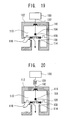
- FIG. 19 is a schematic diagram showing one example of the conventional pilot-controlled switching valve assembly, which is disclosed in Japanese Patent Laid Open Publication No. 09-060969 (Patent Publication 1).
- this type of pilot-controlled switching valve assembly comprises a manual operation member 100 to be pressed by a push button or the like, a push rod 102 having a base end connected integrally or directly to the manual operation member, a pilot valve 104 provided at a distal end of the push rod 102, a diaphragm main valve 108 having a pilot-valve port 106 designed such that the pilot valve 104 is selectively brought into contact therewith and separated therefrom, a housing 112 defining a pressure chamber 110 formed on the side of the back surface of the main valve 110, and a valve seat 114 designed such that a front surface of the main valve 110 is selectively seated thereon and unseated therefrom.
- the pilot-controlled switching valve assembly also includes a sealing member 116 disposed at a portion of the housing 112 allowing the push rod 102 to penetrate therethrough, and a small hole 118 formed in a peripheral portion of the main valve 108.
- FIG. 20 is a schematic diagram showing another example of the conventional pilot-controlled switching valve assembly, which is disclosed in Japanese Patent Laid Open Publication Nos. 11-304245 (Patent Publication 2) and 2001-098596 (Patent Publication 3).
- this type of pilot-controlled switching valve assembly has the same fundamental structure as that of the type illustrated in FIG. 19, and additionally includes a buffer mechanism (coil spring) 120 interposed between the manual operation member 100 and the base end of the push rod 102.
- a buffer mechanism coil spring
- Patent Publication 1 Japanese Patent Laid Open Publication No. 09-060969
- Patent Publication 2 Japanese Patent Laid Open Publication No. 11-304245
- Patent Publication 3 Japanese Patent Laid Open Publication No. 2001-098596
- the aforementioned conventional pilot-controlled switching valve assembly illustrated in FIG. 19 is designed such that the pilot valve 104 disposed within the pressure chamber 110 is brought in contact with and separated from the pilot-valve port 106 of the main valve 108, so that the pilot valve 104 is opened and closed to switch between water-stop and water-discharge states.
- the conventional valve assembly illustrated in FIG. 19 has the difference (unevenness) in operational force between (1) before the pilot valve 104 is brought into contact with the pilot-valve port 106 and (2) after the pilot valve 104 is brought into contact with the pilot-valve port 106, resulting in undesirable operational feeling.
- the pilot-controlled switching valve assembly illustrated in FIG. 20 is provided with the buffer mechanism 120 interposed between the manual operation member 100 and the base end of the pilot valve 104 to absorb a moving distance (displacement) of the pilot valve 104 in its stroke direction so as to provide improved operational feeling.
- a spring load on the buffer mechanism 120 has to be set at a value equal to or greater than the water pressure (if this is not done, the pilot valve 104 cannot be brought into contact with the pilot-valve port 106).
- this type of conventional valve assembly still has the difference (unevenness) in operational force between (1) before the pilot valve 104 is brought into contact with the pilot-valve port 106 and (2) after the pilot valve 104 is brought into contact with the pilot-valve port 106, resulting in an undesirable operational feeling.
- the present invention provides a switching valve assembly for use in a mixing faucet operable to mix hot water and cold water at a desired temperature and selectively stop and discharge the mixed water.
- the switching valve assembly comprises a manual operation member adapted to be moved in response to a pressing operation by a user, a push rod member having a base end joined to the manual operation member, a pilot valve disposed relative to a distal end of the push rod member, a buffer device interposed between the pilot valve and the distal end of the push rod member, a diaphragm main valve having a pilot-valve port designed such that the pilot valve is selectively brought into contact therewith and separated therefrom, a pressure chamber formed on the side of a back surface of the main valve to contain a part of the push rod member, the pilot valve and the buffer device, and a valve seat designed such that a front surface of the main valve is selectively seated thereon and unseated therefrom.
- the push rod member when a water-discharge state is switched to a water-stop state, the push rod member is firstly pressed to bring the pilot valve into contact with the pilot-valve port. During this process, while the push rod member receives an upward force from a water pressure acting on the distal end thereof for an area equivalent to its cross-sectional area and thereby the manual operation member has to be pressed against the upward force, this required force (operational force) is small. Then, after the pilot valve is brought into contact with the pilot-valve port of the main valve, the main valve is moved toward the valve seat and seated on the valve seat so that the water-discharge state is switched to the water-stop state.
- the buffer device disposed within the pressure chamber makes it possible for no force to act thereon before the pilot valve is brought into contact with the pilot-valve port, and only a small force (operational force) may be applied thereto even after the pilot valve is brought into contact with the pilot-valve port.
- operation force operation force
- the difference (unevenness) in operational force which would otherwise occur between (1) before the pilot valve is brought into contact with the pilot-valve port and (2) after the pilot valve is brought into contact with the pilot-valve port can be eliminated during a water-stopping operation, to obtain a desirable operational feeling.
- a spring load on the buffer device can be set at a low value, and thereby a spring constant thereof can be set at a small value to facilitate downsizing of the switching valve assembly.
- the buffer device be a coil spring having a spring constant of 0.01 to 2 N/mm.
- the difference (unevenness) in operational force can be effectively eliminated to obtain a desirable operational feeling.
- the buffer device is a coil spring having a spring constant of 0.01 to 0.75 N/mm.
- the difference (unevenness) in operational force can be eliminated more effectively to obtain a more desirable operational feeling.
- the buffer device be a coil spring having a spring constant of 0.01 to P 1 d 2 ⁇ / (4 ⁇ ) N/mm, wherein ⁇ is the amount of deflection (mm) of the coil spring, P 1 is a water pressure (MPa), and d is the diameter (mm) of a rod portion of the push rod member.
- the difference (unevenness) in operational force can be eliminated more effectively to obtain a more desirable operational feeling.
- the push rod member be formed to have a smaller diameter than that of the pilot-valve port.
- the push rod member formed to have a smaller diameter than that of the pilot-valve port allows an operational force of the manual operation member to be reduced so as to assure a reliable water-stopping performance.
- the push rod member be made of stainless steel.
- the push rod member even if the push rod member has a small diameter, it can have a sufficient corrosion resistance during use in water to obtain enhanced reliability.
- the switching valve assembly of the present invention further includes a pilot-valve switching/holding mechanism operable to selectively switch the pilot valve between a water-stop position and a water-discharge position in conjunction with the movement of the manual operation member and hold the pilot valve in either one of the water-stop position and the water-discharge position, and the pilot-valve switching/holding mechanism has a heart cam structure.
- the pilot-valve switching/holding mechanism having a heart cam structure allows the push rod member to be moved in a reciprocating motion (up-and-down motion) so that a load on a sealing member is reduced to obtain enhanced reliability.
- the mixing faucet comprises a faucet body, a faucet push button for discharging the mixed water directly from a faucet, and a shower push button for discharging the mixed water from a shower
- each of the faucet and shower push buttons has a biasing device adapted to press the push button downward when the push button is located in a water-discharge position and above a top surface of the faucet body.
- each of the faucet and shower push buttons is pressed downward by the biasing device so as to prevent the push button itself from being abnormally moved (vibrated).
- the present invention also provides a switching valve assembly comprising a manual operation member adapted to be moved in response to a pressing operation by a user, a push rod member having a base end joined to the manual operation member, a pilot valve disposed relative to a distal end of the push rod member, a buffer device interposed between the pilot valve and the distal end of the push rod member, a diaphragm main valve having a pilot-valve port designed such that the pilot valve is selectively brought into contact therewith and separated therefrom, a pressure chamber formed on the side of a back surface of the main valve to contain a part of the push rod member, the pilot valve and the buffer device, and a valve seat designed such that a front surface of the main valve is selectively seated thereon and unseated therefrom.
- a pilot-controlled switching valve assembly according to a first embodiment of the present invention will be described. This assembly is applied to a mixing faucet.
- FIG. 1 is a general perspective view showing the mixing faucet to which the pilot-controlled switching valve assembly according to the first embodiment of the present invention is to be applied.
- the mixing faucet indicated by the reference numeral 1 is attached onto a wall surface 2, which is an installation surface of the mixing faucet 1, in such a manner as to protrude therefrom.
- the mixing faucet 1 comprises a plate-shaped heat-insulating cover 4 which is a part of a faucet body.
- the mixing faucet 1 further includes a temperature-adjusting dial 6, a faucet push button 8 for discharging mixed water from a faucet, and a shower push button 10 for discharging the mixed water from a shower, which are individually attached to the heat-insulating cover 4.
- the mixing faucet 1 has a bottom surface covered by another heat-insulating cover 12.
- the mixing faucet 1 is operable, in response to setting a desired water temperature by use of the temperature-adjusting dial 6, to adjust a mixing ratio between hot water and cold water so as to allow the mixed water to be discharged at the desired temperature.
- the mixed water can be discharged from the faucet by operating the faucet push button 8, or discharged from the shower by operating the shower push button 10.
- the shower push button 10 is formed to have a larger size than that of the faucet push button 8 to provide enhanced operationality for users.
- faucet push button 8 and the shower push button 10 are disposed at a position closer to a user as compared to the temperature-adjusting dial 6 to provide enhanced operationality.
- Each of the faucet push button 8 and the shower push button 10 also has an operational surface disposed to be approximately flush with a top surface of the plate-shaped heat-insulating cover 4 to provide enhanced operationality.
- each operational surface of the faucet push button 8 and the shower push button 10 is provided with an anti-slip means 14, such as irregularities.
- a faucet-water outlet 16 and a shower-water outlet 18 are disposed in the vicinity of a frontward portion of the bottom surface of the mixing faucet 1.
- a shower hose 20 in fluid communication with a showerhead (not shown) is connected to the shower-water outlet 18.
- the mixing faucet 1 has right and left side surfaces each provided with an adjusting device for a water shutoff valve 22 and a maintenance hole for a filter and a check valve 24, parts of the valve 22 and the hole being also shown in FIG. 2.
- the adjusting device and the maintenance hole in the right side surface are used for supplying cold water to the mixed faucet 1, and the adjusting device and the maintenance hole in the left side surface are used for supplying hot water to the mixed faucet 1.
- One side surface of the mixing faucet 1 to be fixed to the wall surface is formed with a pair of connection portions designed such that a cold-water supply pipe 26 (see FIG. 2) and a hot-water supply pipe are connected thereto, respectively.
- a user can set a desired temperature using the temperature-adjusting dial 6, and then push the faucet push button 8 when the user wants to obtain feed water from the faucet or push the shower push button 10 when the user wants to obtain feed water from the shower, so as to immediately obtain the feeding of the mixed water at the desired temperature. Then, the user can re-push the push buttons 8, 10 to stop the mixed water.
- each of the flow volumes of cold water and hot water supplied, respectively, from the cold-water supply pipe 26 and the hot-water supply pipe (not shown) into the mixing faucet 1 is reduced to an appropriate value by a corresponding one of the shutoff valves 22 for cold water and hot water.
- each of the adjusted cold water and hot water passes through corresponding ones of the filters and check valves 24 for cold water and hot water, and flows into a temperature control valve, which is a thermostat-type hot/cold water mixing valve.
- the cold water and hot water are automatically adjusted through the temperature control valve to have the desired temperature, and the mixed water flows out of the temperature control valve.
- the mixed water is discharged from one or both of the faucet and the shower through a corresponding one or both of after-mentioned two switching valve units (pilot-controlled switching valve assemblies) 30, 32, which are provided, respectively, for the faucet and the shower (FIG. 2 shows only the pilot-controlled switching valve assembly 32).
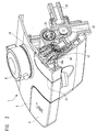
- FIG. 2 is a perspective view showing the state after the pilot-controlled switching valve assembly according to the first embodiment of the present invention is attached to a mixing faucet
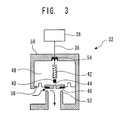
- FIG. 3 is a schematic diagram showing the fundamental structure of the pilot-controlled switching valve assembly according to the first embodiment of the present invention.
- a pair of switching valve units 30, 32 each of which is the pilot-controlled switching valve assembly according to the first embodiment (FIG. 2 shows only the pilot-controlled switching valve assembly 32) are disposed in contact, respectively, with bottom surfaces of the faucet and shower push buttons 8, 10 of the mixing faucet 1.
- Each of the switching value units 30, 32 is attached to the body of the mixing faucet 1 with a switching-valve-unit attaching nut 34.
- This switching-valve-unit attaching nut 34 has a top end formed with an extension 34a to prevent water from getting into each of the switching value unit 30, 32.
- the faucet switching valve unit 30 and the shower switching valve unit 32 have the same structure, and thus the following description will be given only about the shower switching valve unit 32.
- the switching valve unit 32 assembly comprises a manual operation member 34 adapted to be moved in response to a pressing operation in which a user presses the shower push button 10, a push rod 38 having a base end joined to the manual operation member 36, and a pilot valve 38 disposed relative to a distal end of the push rod 38, wherein a coil spring 42 serving as a buffer device is interposed between a pilot valve 40 and the distal end (lower end) of the push rod 38.
- the switching valve unit 32 further includes a diaphragm main valve 46 having a pilot-valve port (pressure release hole) 44 designed such that the pilot valve 40 is selectively brought into contact therewith and separated therefrom, a housing 50 defining a pressure chamber 48 which is formed on the side of a back surface of the main valve 46 to contain a part of the push rod 38, the pilot valve 40 and the coil spring 42, a valve seat 52 designed such that a front surface of the main valve 46 is selectively seated thereon and unseated therefrom, a sealing member 54 at a portion of the housing 50 allowing the push rod 39 to penetrate therethrough, and a small hole (primary-pressure inlet port) 56 formed in a peripheral portion of the main valve 46.
- a small hole primary-pressure inlet port
- This switching valve unit 32 is designed such that the pilot valve 40 disposed within the pressure chamber 48 is brought in contact with and separated from the pilot-valve port 44 of the main valve 46, so that the pilot valve 40 is opened and closed to switch between water-stop and water-discharge states.
- the coil spring 42 serving as a buffer device is disposed between the push rod 38 and the pilot valve 40, or within the pressure chamber 48.
- the pilot valve 40 In an operation for switching from the water-stop state to the water-discharge state, when the manual operation member 36 is pressed, the pilot valve 40 is separated from the pilot-valve port (pressure release hole) 44 by means of an after-mentioned pilot-valve holding/switching mechanism 62 and biasing spring 68. Thus, the pressure chamber 48 is opened, and the main valve 46 is unseated from the valve seat 52, so that the water-stop state is switched to the water-discharge state (see FIG. 5).
- the moving speed of the main valve 46 is intentionally reduced. This reduction is done to prevent a water hammer phenomenon from occurring when the main valve 46 is closed.
- the small hole 56 is typically set to have a very small diameter to reduce an inflow speed of water flowing into the pressure chamber 48, whereby the moving speed (closing speed) of the main valve 46 is reduced to prevent a water hammer phenomenon from occurring when the main valve 46 is closed.
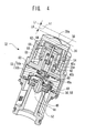
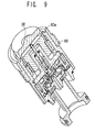
- FIG. 4 is a sectional view showing the switching valve unit (pilot-controlled switching valve assembly) according to the first embodiment, wherein the switching valve unit is in a water-stop state (closed state).
- FIG. 5 is a sectional view showing the switching valve unit (pilot-controlled switching valve assembly) according to the first embodiment, wherein the switching valve unit is in a water-discharge state (open state).
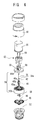
- FIG. 6 is an exploded diagram showing components of the switching valve unit (pilot-controlled switching valve assembly) according to the first embodiment.
- the switching valve unit 32 comprises the manual operation member 36, the push rod 38, the pilot valve 40, the coil spring 42 serving as a buffer device, and the diaphragm main valve 46 having the pilot-valve port (pressure release hole) 44, the housing 50 (50a, 50b) defining the pressure chamber 48, the valve seat 52, the sealing member 54 and the small hole 56, which have already been described in conjunction with FIG. 3.
- a cleaning pin 58 is inserted into the above small hole (primary-pressure inlet port) 56 to narrow the cross-sectional area of the primary-pressure inlet port of the small hole 56. This allows the inflow speed of the primary pressure into the pressure chamber to be reduced so as to provide a lowered closing speed of the main valve 46 to prevent a water hammer phenomenon from occurring when the main valve 46 is closed, as described above.
- the housing 50 defining the pressure chamber 48 comprises a first housing 50a surrounding a space in which the pilot valve 40 is primarily disposed, and a second housing 50b surrounding a space on the side of the back surface of the main valve 46.
- the switching valve unit 32 also includes an assembling nut 60 disposed around the outermost periphery thereof to assemble four components, namely the manual operation member 36, the first housing 50a, the second housing 50b and the valve seat 52, so as to make up the switching valve unit 32.
- the switching valve unit 32 further includes a pilot-valve switching/holding mechanism 62.
- This pilot-valve switching/holding mechanism 62 is designed to be moved in conjunction with the aforementioned faucet push button 8 and the shower push button 10, and have functions for repeatedly switching the pilot valve 40 between a water-stop position corresponding to the water-stop state and a water-discharge position corresponding to the water-discharge state, every time either one or both of the push buttons 8, 10 is pressed or every time the manual operation member 36 is pressed, and holding the pilot valve 40 in either one of the water-stop position and the water-discharge position.
- pilot-valve switching/holding mechanism 62 may be a mechanism to be commonly used for a knock mechanism for knock-type ballpoint pens
- the first embodiment employs a heart cam mechanism comprising a pin 64 adapted to be moved in conjunction with the manual operation member 36, an inverted heart-shaped cam groove 66 formed in the outer peripheral surface of the first housing 50a to allow the lower portion of the pin 64 to be moved therealong while being elastically deformed, and a holding protrusion 68 adapted to hold the pin 64 in the water-stop state (closed state), as shown in FIG. 4.
- the pilot-valve switching/holding mechanism 62 consisting of the heart cam mechanism allows only a reciprocating motion (up-and-down motion) of the push rod 38 to act on the sealing member 54 sealing the pressure chamber 48 without a rotational motion of the push rod 38 as in the above knock mechanism. Thus, the load on the sealing member 54 is reduced to obtain enhanced reliability.
- the reference numeral 69 indicates a biasing spring.
- the coil spring 42 serving as a buffer device for absorbing the moving distance (displacement) of the push rod 38 in its stroke direction is disposed at the distal end (lower end) of the push rod 38 and within the pressure chamber 48, as described above.
- the distal end (lower end) of the push rod 38 is formed as a large diameter portion 38a, and the top end of the pilot valve 40 has a packing 40a attached thereto.
- the pilot valve 40 has a hollow portion 40b, and the coil spring 42 is contained in the hollow portion 40b.
- the pilot valve 40 has a top wall formed with an insertion hole 40c allowing the push rod 38 to be slidably inserted thereinto.
- the pilot valve 40 is made of an elastically deformable resin material.
- the large diameter portion 38a at the distal end of the push rod 38 is brought into engagement with the top wall of the pilot valve 40 by the biasing force of the coil spring 42, and thereby the pilot valve 40 is moved in conjunction with the movement of the push rod 38 and unseated from the pilot-valve port 44 formed in the main valve 46 (see FIG. 5).
- the push rod 38 when the operational force of the manual operation member 36 is to be reduced, it is desirable to minimize the diameter of the push rod 38, because the push rod 38 receives an upward force from a water pressure in the pressure chamber 48 (water pressure to the distal end of the push rod 38 for an area equivalent to its cross-sectional area).
- the push rod 38 may be formed to have a smaller diameter than that of the pilot-valve port 44 of the main valve 46. This makes it possible to reduce the operational force (pressing force) even under a high-pressure condition, and assure a reliable water-stopping performance.
- the primary pressure acts on the pilot valve 40 in a direction allowing the pilot valve 40 to be seated on the pilot-valve port 44 so that the water-stopping performance is further assured.
- the push rod 38 is made of stainless steel. Thus, even if the push rod 38 is designed to have a small diameter, it can have a sufficient corrosion resistance during use in water to obtain enhanced reliability.
- the pilot-controlled switching valve assembly (switching valve unit) according to the first embodiment can reduce a load acting on the coil spring serving as a buffer device (spring load), and thereby the coil spring can be set to have a lower spring constant. This makes it possible to obtain enhanced operationality and facilitate downsizing, the reason for which will be explained with reference to FIGS. 7(a) to 8(b).
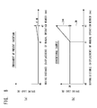
- FIG. 7(a) is a graph showing the relationship between a moving distance (displacement) (mm) of the manual operation member 36 and an operational force F (N) during the water-stopping operation (during switching from the water-discharge state to the water-stop state) in the pilot-controlled switching valve assembly according to the first embodiment.
- FIG. 7(b) is a graph showing the relationship between a moving distance (displacement) (mm) of the manual operation member and an operational force F (N) during the water-stopping operation in the conventional example in FIG. 20.
- FIG. 8(a) is a graph showing the relationship between a moving distance (displacement) (mm) of the manual operation member 36 and a spring load (N) acting on the coil spring during the water-stopping operation in the pilot-controlled switching valve assembly according to the first embodiment.
- FIG. 8(b) is a graph showing the relationship between a moving distance (displacement) (mm) of the manual operation member and a spring load (N) acting on the coil spring during the water-stopping operation in the conventional example in FIG. 20.
- d0 indicates a position where the water-stopping operation is initiated
- d1 indicates a position where the pilot valve 40 is brought into contact with the pilot-valve port 44
- d2 indicates the lowermost position to which the manual operation member 36 can be moved (displaced) by the pilot-valve switching/holding mechanism 62.
- the coil spring 42 is incorporated in the hollow portion 40b of the pilot valve 40 while a very small load (e.g. 0.1 N) is applied thereto during assembling.
- the operational force is kept at 3 N before the pilot valve 40 is brought into contact with the pilot-valve port 44.
- the spring constant is set at a small value providing a spring load of about 0.4 N at the lowermost position d2 to which the manual operation member 36 can be moved.
- the amount of deflection ( ⁇ ) of the coil spring 42 is 4 mm.
- the coil spring is disposed outside the pressure chamber.
- the conventional example is required to use a coil spring having a large spring constant capable of generating only an extremely small amount of deflection even if 3.0 N of spring load acts thereon. This value is extremely large as compared to the spring load acting on the coil spring in the first embodiment, which is approximately zero.
- this coil spring is essentially designed to have a large spring, and thereby a large operational force is required to deflect the coil spring.
- a coil spring having a spring constant of 6 N/mm generating a displacement of 0.5 mm relative to a spring load of 3N is used, and the amount of deflection ( ⁇ ) of the coil spring for absorbing the moving distance (displacement) of the manual operation member is 4 mm, 24 N of operational force is required.
- a preferable range of the spring constant of the coil spring serving as a buffer device in the pilot-controlled switching valve assembly (switching valve unit) in the first embodiment will be described below.
- the spring constant of the coil spring in the above conventional example has to be set at a large value of 6 N/mm or more due to the buffer device (coil spring) disposed outside the pressure chamber, it is preferable that the spring constant of the coil spring in the first embodiment be set in the range of 0.01 to 2 N/mm.
- the coil spring having a spring constant set in the above range makes it possible to eliminate the difference (unevenness) in operational force during the water-stopping operation, which would otherwise occur between (1) before the pilot valve 40 is brought into contact with the pilot-valve port 44 and (2) after the pilot valve 40 is brought into contact with the pilot-valve port 44, so as to obtain a desirable operational feeling, as compared to the conventional example.
- an operational force (3N) before the pilot valve 40 is brought into contact with the pilot-valve port 44 is an initial-stage operational force
- an operational force (spring load) to be added after the pilot valve 40 is brought into contact with the pilot-valve port 44 is equal to or less than the initial-stage operational force (3N)
- the difference (unevenness) in operational force during the water-stopping operation which would otherwise occur between (1) before the pilot valve 40 is brought into contact with the pilot-valve port 44 and (2) after the pilot valve 40 is brought into contact with the pilot-valve port 44, can be effectively eliminated to obtain a desirable operational feeling as compared to the conventional example.
- the coil spring may be set to have a spring constant of 0.01 to P 1 d 2 ⁇ / (4 ⁇ ) N/mm, wherein ⁇ is the amount of deflection (mm) of the coil spring, P 1 is a water pressure (MPa), and d is the diameter (mm) of a rod portion of the push rod member.
- the spring constant of the coil spring may be set in the range of 0.01 to 0.75 N/mm. This makes it possible to eliminate the difference (unevenness) in operational force during the water-stopping operation, which would otherwise occur between (1) before the pilot valve 40 is brought into contact with the pilot-valve port 44 and (2) after the pilot valve 40 is brought into contact with the pilot-valve port 44, so as to obtain an improved desirable operational feeling.
- the minimum value of the spring constant of the coil spring in the first embodiment is set at 0.01 N/mm based on three required conditions for reducing the spring constant of the coil spring: reducing the diameter of a spring wire rod of the coil spring; reducing the number of turns of the coil spring; and increasing the diameter of the coil spring.
- the pilot-controlled switching valve assembly according to the first embodiment allows the spring constant of the coil spring 42 to be set at a smaller value than that in the conventional valve assembly having the coil spring disposed outside the pressure chamber.
- the pilot-controlled switching valve assembly makes it possible to reduce a spring load acting on the coil spring to obtain a desirable operational feeling and facilitate downsizing of the assembly to a large degree as compared to the conventional valve assembly.
- the shower push button 10 or another push button is strongly pressed so as to rapidly bring the pilot valve 40 into contact with the pilot-valve port 44 to close the pilot valve 40, a load on a diaphragm of the diaphragm main valve 46 will be instantaneously increased to cause a problem about deterioration in durability of the diaphragm.
- the spring constant of the coil spring 42 can be set at a small value to reduce a spring load.
- the moving speed of the main valve 46 can be lowered to prevent the occurrence of an instantaneous large load acting on the main valve so as to provide enhanced durability of the diaphragm.
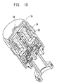
- a pilot-controlled switching valve assembly has an extension portion 60a formed in a top end portion of the assembling nut 60 in contact with the manual operation member 36.
- This extension portion 60a substantially precludes water from getting through the clearance between the outer peripheral surface of the manual operation member 36 and the extension portion 60a of the assembling nut 60 to provide an enhanced water-resistant function. This can effectively prevent the occurrence of operational defects or abnormal noises during operation due to the pinching of dusts and/or the attachment of scales, and provides enhanced sanitary conditions.
- a pilot-controlled switching valve assembly according to the third embodiment is provided with a manual-operation-member cover 70 for covering the top surface and outer peripheral surface of the manual operation member 36.
- This manual-operation-member cover 70 is fixed to the outer peripheral surface of the manual operation member 36 by the assembling nut 60 and the switching-valve-unit attaching nut 34 (without the extension portion 34a).
- the manual-operation-member cover 70 substantially precludes water from getting into the switching valve unit to provide an enhanced water-resistant function. This can effectively prevent the occurrence of operational defects or abnormal noises during operation due to the pinching of dust and/or the attachment of scales, and provides enhanced sanitary conditions.
- FIG. 11 is a perspective view showing an assembly of the plate-shaped heat-insulating cover 4, the faucet push button 8 and the shower push button 10, which are components of the mixing faucet 1 in FIG. 2.
- FIG. 12 is a perspective top plan view showing the assembly in FIG. 11, wherein the shower push button 10 is pressed.
- FIG. 13 is a perspective back view showing the assembly in FIG. 12.
- FIG. 14 is a perspective top plan view showing the shower push button 10.
- FIG. 15 is a perspective back view showing the shower push button 10 in FIG. 14.
- the faucet push button 8 and the shower push button 10 have the same structure, and thus the following description will be made regarding only the shower push button 10 as an example.
- the shower push button 10 comprises a button operation portion 80, an arm portion 82 allowing the shower push button 10 to be attached to the heat-insulating cover 4 as a part of the faucet body, and a plate spring portion 84 serving as a biasing device allowing the shower push button 10 to be biased toward the heat-insulating cover 4.
- the button operation portion 80, the arm portion 82 and the plate spring portion 84 are integrally formed in a single piece, and made of polypropylene.
- each of the attaching protrusions 82a is adapted to be fitted into a corresponding one of concave portions of an attaching flange 4a formed in the heat-insulating cover 4 so that the arm portion 82 is attached to the heat-insulating cover 4.
- the shower push button 10 is swingable about the concave portions of the flange 4a of the heat-insulating cover 4.
- the plate spring portion 84 of the shower push button 10 has a pair of elastically deformable regions 84a each having a base end joined to the arm portion 82, and a pair of engagement regions 84b each formed at a distal end of the corresponding deformable region 84a.
- a joined position 84c between the plate spring portion 84 and the arm portion 82 is set to maximize a distance from the protrusion 82a of the arm portion 82 (or at a position close to the button operation portion 80).
- the switching valve units 30, 32 (FIG. 2 shows only the switching valve unit 32) are disposed to be in contact, respectively, with the bottom surfaces of the faucet and shower push buttons 8, 10 of the mixing faucet 1.
- the manual operation member 36 of the switching valve unit 32 in the water-stop state (closed state), has a top portion 36a in contact with the bottom surface of the shower push button 10, and the top portion 36a is positioned at a height level L0 by the pilot-valve switching/holding mechanism 62.
- this height level L0 corresponds to a position where the top surface of the shower push button 10 and the top surface (front surface) of the heat-insulating cover 4 have the same height level.
- the state of the height level L0 corresponds to a position illustrated in FIG. 16(a).
- the top portion 36a of the manual operation member 36 of the switching valve unit 32 in contact with the bottom surface of the shower push button 10 is positioned at a height level L1 by the pilot-valve switching/holding mechanism 62.
- This height level L1 is higher than the height level L0 in FIG. 2 by h1.
- the state of the height level L1 corresponds to a position illustrated in FIG. 16(c).
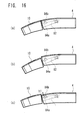
- FIGS. 16 (a) to (c) are side views showing respective height levels during a user's operation of the shower push button 10.
- FIG. 16(a) shows a position in the water-stop (closed) state, where the top surface of the shower push button 10 and the top surface (front surface) of the heat-insulating cover 4 have the same height level.
- the engagement regions 84b of the plate spring portion 84 are in non-contact with or in contact slightly with the back surface of the heat-insulating cover 4. This prevents the plate spring portion 84 from generating a biasing force in the water-stop state to avoid the occurrence of permanent deformation therein.
- FIG. 16(b) shows a position of the shower push button 10 during the course of switching from the water-stop state to the water-discharge state after a user presses the shower push button 10, or in a transient state.
- FIG. 16(c) shows a position of the shower push button 10 after the completion of the water-discharging operation by a user from the position in FIG. 16(b).
- the top surface of the shower push button 10 is located at a higher position than that of the heat-insulating cover 4 by h1. In this position, as shown in FIG.
- the shower push button 10 is pressed toward the back surface of the heat-insulating cover 4 to cause an elastic deformation in the deformable regions 84a of the plate spring portion 84, so as to generate a force allowing the shower push button 10 to be pressed downward toward the switching valve unit.
- the shower push button 10 is pressed downward by the plate spring portion 84 to prevent the push button itself from being abnormally moved (vibrated).
- this shower push button 10 comprises a button operation portion 80, a arm portion 82 allowing the shower push button 10 to be attached to the heat-insulating cover 4, and a plate spring portion 86 allowing the shower push button 10 to be biased toward the heat-insulating cover 4, as in the above embodiment.
- the plate spring portion 86 in this modification is formed to extend parallel to the arm portion 82.
- the plate spring portion 86 has a base end 86a joined to the back surface of the operation portion 80 and a distal end 86b pressed onto the back surface of the heat-insulating cover 4. Further, an elastically deformable region 86c is formed between the base end 86a and the distal end 86b.
- the shower push button 10 When the top surface of the shower push button 10 is located at a higher position than that of the top surface (front surface) of the heat-insulating cover 4 during the water discharging operation, the shower push button 10 is pressed downward by the elastically deformed deformable region 86c
- the shower push button 10 is pressed downward by the plate spring portion 84 to prevent the push button itself from being abnormally moved (vibrated).
- the switching valve unit of the present invention can provide a desirable operational feeling without unevenness in operational force, and can facilitate downsizing.
Landscapes
- Engineering & Computer Science (AREA)
- General Engineering & Computer Science (AREA)
- Mechanical Engineering (AREA)
- Public Health (AREA)
- Life Sciences & Earth Sciences (AREA)
- Hydrology & Water Resources (AREA)
- Health & Medical Sciences (AREA)
- Water Supply & Treatment (AREA)
- Multiple-Way Valves (AREA)
- Fluid-Driven Valves (AREA)
- Mechanically-Actuated Valves (AREA)
- Domestic Plumbing Installations (AREA)
- Compressor (AREA)
- Feeding And Controlling Fuel (AREA)
Abstract
Description
Claims (9)
- A switching valve assembly for use in a mixing faucet operable to mix hot water and cold water at a desired temperature and selectively stop and discharge said mixed water, said switching valve assembly comprising:a manual operation member adapted to be moved in response to a pressing operation by a user;a push rod member having a base end joined to said manual operation member;a pilot valve disposed relative to a distal end of said push rod member;a buffer device interposed between said pilot valve and said distal end of said push rod member;a diaphragm main valve having a pilot-valve port designed such that said pilot valve is selectively brought into contact therewith and separated therefrom;a pressure chamber formed on the side of a back surface of said main valve to contain a part of said push rod member, said pilot valve and said buffer device; anda valve seat designed such that a front surface of said main valve is selectively seated thereon and unseated therefrom.
- The switching valve assembly according to claim 1, wherein said buffer device is a coil spring having a spring constant of 0.01 to 2 N/mm.
- The switching valve assembly according to claim 1, wherein said buffer device is a coil spring having a spring constant of 0.01 to 0.75 N/mm.
- The switching valve assembly according to claim 1, wherein said buffer device is a coil spring having a spring constant of 0.01 to P1d2π / (48) N/mm, wherein δ is the amount of deflection (mm) of said coil spring, P1 is a water pressure (MPa), and d is the diameter (mm) of a rod portion of said push rod member.
- The switching valve assembly according to any of claims 1 to 4, wherein said push rod member is formed to have a smaller diameter than that of said pilot-valve port.
- The switching valve assembly according to any of claims 1 to 5, wherein said push rod member is made of stainless steel.
- The switching valve assembly according to any of claims 1 to 6, which further includes a pilot-valve switching/holding mechanism operable to selectively switch said pilot valve between a water-stop position and a water-discharge position in conjunction with the movement of said manual operation member and hold said pilot valve in either one of said water-stop position and said water-discharge position, said pilot-valve switching/holding mechanism having a heart cam structure.
- The switching valve assembly according to any of claims 1 to 7, wherein said mixing faucet comprises a faucet body, a faucet push button for discharging the mixed water directly from a faucet, and a shower push button for discharging the mixed water from a shower, each of said faucet and shower push buttons having a biasing device adapted to press said push button downward when said push button is located in a water-discharge position and above a top surface of said faucet body.
- , A switching valve assembly comprising:a manual operation member adapted to be moved in response to a pressing operation by a user;a push rod member having a base end joined to said manual operation member;a pilot valve disposed relative to a distal end of said push rod member;a buffer device interposed between said pilot valve and said distal end of said push rod member;a diaphragm main valve having a pilot-valve port designed such that said pilot valve is selectively brought into contact therewith and separated therefrom;a pressure chamber formed on the side of a back surface of said main valve to contain a part of said push rod member, said pilot valve and said buffer device; anda valve seat designed such that a front surface of said main valve is selectively seated thereon and unseated therefrom.
Applications Claiming Priority (3)
| Application Number | Priority Date | Filing Date | Title |
|---|---|---|---|
| JP2002256208 | 2002-08-30 | ||
| JP2002256208 | 2002-08-30 | ||
| PCT/JP2003/011158 WO2004020886A1 (en) | 2002-08-30 | 2003-09-01 | Opening and closing valve |
Publications (3)
| Publication Number | Publication Date |
|---|---|
| EP1548344A1 true EP1548344A1 (en) | 2005-06-29 |
| EP1548344A4 EP1548344A4 (en) | 2008-09-10 |
| EP1548344B1 EP1548344B1 (en) | 2011-11-30 |
Family
ID=31972942
Family Applications (1)
| Application Number | Title | Priority Date | Filing Date |
|---|---|---|---|
| EP20030791442 Expired - Lifetime EP1548344B1 (en) | 2002-08-30 | 2003-09-01 | Opening and closing valve |
Country Status (7)
| Country | Link |
|---|---|
| US (1) | US7296593B2 (en) |
| EP (1) | EP1548344B1 (en) |
| JP (1) | JP3632976B2 (en) |
| CN (1) | CN100387882C (en) |
| AT (1) | ATE535744T1 (en) |
| AU (1) | AU2003261872A1 (en) |
| WO (1) | WO2004020886A1 (en) |
Cited By (11)
| Publication number | Priority date | Publication date | Assignee | Title |
|---|---|---|---|---|
| WO2007080237A1 (en) * | 2006-01-12 | 2007-07-19 | Farhooman Davoudi | Non-flush-mounted shower or over-bath shower wall mixer tap offering simultaneous or separate multiple functions |
| EP2239486A1 (en) * | 2009-04-08 | 2010-10-13 | Kohler Mira Limited | Valves |
| ITPD20090257A1 (en) * | 2009-09-08 | 2011-03-09 | Sit La Precisa S P A Con Socio Uni Co | VALVE GROUP FOR THE CONTROLLING OF THE DISTRIBUTION OF A FUEL GAS, IN PARTICULAR FOR THE DISTRIBUTION THROUGH A GAS COUNTER, AND GAS COUNTER INCLUDING THE VALVE GROUP |
| FR2959256A1 (en) * | 2010-04-27 | 2011-10-28 | Presto Robinets Sa | IMPROVEMENTS ON SHOWER COLUMNS |
| WO2014139661A1 (en) * | 2013-03-11 | 2014-09-18 | Neoperl Gmbh | Hand-held shower holding device |
| CN106051212A (en) * | 2016-06-29 | 2016-10-26 | 北京科勒有限公司 | Flow control valve |
| EP3249271A1 (en) * | 2016-02-22 | 2017-11-29 | Neoperl GmbH | Valve actuating device and method for switching a valve assembly |
| RU187492U1 (en) * | 2017-03-28 | 2019-03-11 | Общество с ограниченной ответственностью "УралГазРемонт" | Pressure control valve |
| EP3640405A1 (en) * | 2018-10-19 | 2020-04-22 | Fabrizio Nobili | System for opening and closing water for a shower head, hand shower or a bathroom or kitchen mixer |
| CN111535403A (en) * | 2020-05-08 | 2020-08-14 | 郭春燕 | Shower mechanism with water-saving function |
| US11408534B2 (en) | 2016-02-22 | 2022-08-09 | Neoperl Gmbh | Valve-actuating device |
Families Citing this family (23)
| Publication number | Priority date | Publication date | Assignee | Title |
|---|---|---|---|---|
| EP1562009A1 (en) * | 2004-02-06 | 2005-08-10 | Thermagen S.A. | Actuating device for self cooling packaging |
| JP5041344B2 (en) * | 2008-02-14 | 2012-10-03 | Toto株式会社 | Faucet device and method of manufacturing faucet equipment having the same |
| DE102009002551A1 (en) * | 2009-04-22 | 2010-10-28 | Robert Bosch Gmbh | Valve for controlling a flow |
| EP2455644B1 (en) | 2010-11-22 | 2015-04-29 | Yuan Mei Corporation | Magnetic control valve |
| EP2466176B1 (en) | 2010-12-14 | 2013-10-02 | Yuan Mei Corporation | Switch device for water conduit valve |
| US9080685B2 (en) * | 2012-02-07 | 2015-07-14 | Tianbaili new technology development Co. Ltd | Double-switched automatic sprinkler valve |
| US9581255B2 (en) | 2012-07-23 | 2017-02-28 | Henning, Inc. | Multiple proportion delivery systems and methods |
| EP2865929B1 (en) * | 2013-10-25 | 2017-01-25 | Fabrizio Nobili | Device for adjusting the water in a shower or bath or kitchen sink |
| JP6768193B2 (en) * | 2016-05-06 | 2020-10-14 | Toto株式会社 | Flow control valve |
| CN106051208B (en) * | 2016-07-27 | 2019-11-29 | 路达(厦门)工业有限公司 | Switch the external member of valve cell, fluid switch and fluid switch |
| EP3538715A4 (en) * | 2016-11-08 | 2020-06-10 | Sidus Technologies, Inc. | REVERSAL TECHNOLOGY FOR TAPS |
| EP3366958B1 (en) * | 2017-02-23 | 2019-02-20 | Flühs Drehtechnik GmbH | Valve top |
| CN108869804B (en) * | 2017-05-08 | 2024-04-09 | 漳州松霖智能家居有限公司 | A water outlet terminal with water purification function |
| DE202017103194U1 (en) * | 2017-05-26 | 2018-08-28 | Neoperl Gmbh | sanitary valve |
| US11892094B2 (en) * | 2017-09-07 | 2024-02-06 | Neoperl Gmbh | Valve arrangement |
| CN208687007U (en) * | 2018-06-27 | 2019-04-02 | 北京科勒有限公司 | Flow control valve valve |
| DE202018103806U1 (en) | 2018-07-03 | 2019-10-14 | Neoperl Gmbh | Valve, fitting and use of a valve |
| USD890884S1 (en) | 2018-12-28 | 2020-07-21 | Spectrum Brands, Inc. | Shower column |
| US11156302B2 (en) | 2019-05-30 | 2021-10-26 | Kohler Co. | Push-button tub and shower diverter |
| GB2595462B (en) * | 2020-05-26 | 2022-08-24 | Kohler Mira Ltd | Ablutionary fitting control |
| DE202021100839U1 (en) * | 2021-02-19 | 2022-05-27 | Neoperl GmbH | sanitary valve |
| DE202021100840U1 (en) * | 2021-02-19 | 2022-05-27 | Neoperl Gmbh | sanitary valve |
| CN114165618B (en) * | 2021-12-11 | 2024-08-27 | 珠海格力电器股份有限公司 | On-off mechanism and water purifying equipment |
Family Cites Families (30)
| Publication number | Priority date | Publication date | Assignee | Title |
|---|---|---|---|---|
| DE2444469A1 (en) * | 1974-09-18 | 1976-04-01 | Gen Hydraulics Proprietary Ltd | Push button operated on-off water valve - has permanent magnet to lift piston off pilot hole in membrane |
| DE2823775C2 (en) * | 1978-05-31 | 1980-06-19 | Bodenseewerk Perkin-Elmer & Co Gmbh, 7770 Ueberlingen | Pressure medium switch |
| FR2481404A1 (en) * | 1980-04-24 | 1981-10-30 | Fonderie Soc Gen De | Water feed valve with push flow control - has rotary sleeve regulation cutting by pass flow for membrane to move washer onto seat |
| US4546791A (en) * | 1984-03-20 | 1985-10-15 | Huang E Jen | Safety valve |
| JPS6179077U (en) * | 1984-10-30 | 1986-05-27 | ||
| JPS62172879U (en) * | 1986-04-23 | 1987-11-02 | ||
| DE8704797U1 (en) * | 1987-03-31 | 1987-07-23 | Hubert Schell Gmbh & Co Kg, 5960 Olpe | Pressure flusher |
| CN87210709U (en) * | 1987-11-06 | 1988-05-25 | 王延玲 | Self-closed flush valve |
| JPH0198982U (en) * | 1987-12-24 | 1989-07-03 | ||
| US4844554A (en) * | 1988-05-26 | 1989-07-04 | General Signal Corporation | Empty-load valve device |
| CA2013434C (en) * | 1989-03-30 | 2000-05-30 | Shinji Shibata | Flush water supply system for toilet stool |
| US5204999A (en) * | 1989-03-30 | 1993-04-27 | Toto Ltd. | Flush water supply system for toilet stool |
| US5217043A (en) * | 1990-04-19 | 1993-06-08 | Milic Novakovic | Control valve |
| JPH0464783A (en) * | 1990-07-02 | 1992-02-28 | Matsushita Electric Ind Co Ltd | Stop and flow regulation device |
| CN2083596U (en) * | 1991-01-21 | 1991-08-28 | 戴勤彬 | Pneumatic running water freezing-proof device |
| US5502845A (en) * | 1991-06-10 | 1996-04-02 | Toto Ltd. | Siphon-jet flush water supply system for toilet stool |
| CN1085763C (en) * | 1994-04-08 | 2002-05-29 | 东陶机器株式会社 | Connecting device for stool and drainage pipe |
| JPH07324362A (en) | 1994-05-31 | 1995-12-12 | Toto Ltd | Toilet flushing tank device |
| FR2727736B1 (en) * | 1994-12-02 | 1997-01-24 | Eaton Sa Monaco | VALVE CONTROLLED BY A FLUID |
| JP3651005B2 (en) * | 1994-12-28 | 2005-05-25 | 東陶機器株式会社 | Flush toilet |
| JP3577647B2 (en) * | 1995-08-18 | 2004-10-13 | パロマ工業株式会社 | Gas water heater faucet |
| US6115853A (en) * | 1996-08-06 | 2000-09-12 | Toto Ltd. | Toilet bowl |
| KR100388951B1 (en) | 1996-10-15 | 2003-06-25 | 토토주식회사 | Flush Toilet |
| CN1246545C (en) | 1997-01-13 | 2006-03-22 | 东陶机器株式会社 | Flushing water closet and cast molding device thereof |
| JP4059973B2 (en) * | 1998-03-30 | 2008-03-12 | パロマ工業株式会社 | Gas water tap |
| JP3943712B2 (en) * | 1998-04-24 | 2007-07-11 | パロマ工業株式会社 | Main stop type gas water heater |
| JP4142219B2 (en) * | 1999-09-29 | 2008-09-03 | 株式会社Inax | Water discharge device |
| US20030213055A1 (en) * | 1999-10-29 | 2003-11-20 | Toto Ltd. | Drainage device for siphon action toilet |
| EP1273725A4 (en) * | 2000-03-31 | 2004-07-14 | Toto Ltd | Flush toilet |
| JP3687734B2 (en) | 2000-08-25 | 2005-08-24 | テクノエクセル株式会社 | Manual and electromagnetic water supply valve device |
-
2003
- 2003-09-01 US US10/525,994 patent/US7296593B2/en not_active Expired - Lifetime
- 2003-09-01 CN CNB038201267A patent/CN100387882C/en not_active Expired - Fee Related
- 2003-09-01 AU AU2003261872A patent/AU2003261872A1/en not_active Abandoned
- 2003-09-01 WO PCT/JP2003/011158 patent/WO2004020886A1/en not_active Ceased
- 2003-09-01 EP EP20030791442 patent/EP1548344B1/en not_active Expired - Lifetime
- 2003-09-01 JP JP2004532785A patent/JP3632976B2/en not_active Expired - Lifetime
- 2003-09-01 AT AT03791442T patent/ATE535744T1/en active
Cited By (18)
| Publication number | Priority date | Publication date | Assignee | Title |
|---|---|---|---|---|
| WO2007080237A1 (en) * | 2006-01-12 | 2007-07-19 | Farhooman Davoudi | Non-flush-mounted shower or over-bath shower wall mixer tap offering simultaneous or separate multiple functions |
| EP2239486A1 (en) * | 2009-04-08 | 2010-10-13 | Kohler Mira Limited | Valves |
| RU2528193C2 (en) * | 2009-09-08 | 2014-09-10 | Метерсит | Valve assembly and gas meter, comprising named valve assembly |
| ITPD20090257A1 (en) * | 2009-09-08 | 2011-03-09 | Sit La Precisa S P A Con Socio Uni Co | VALVE GROUP FOR THE CONTROLLING OF THE DISTRIBUTION OF A FUEL GAS, IN PARTICULAR FOR THE DISTRIBUTION THROUGH A GAS COUNTER, AND GAS COUNTER INCLUDING THE VALVE GROUP |
| WO2011029638A1 (en) * | 2009-09-08 | 2011-03-17 | Sit La Precisa S.P.A. Con Socio Unico | Valve unit and gas meter including said valve unit |
| US9151024B2 (en) | 2010-04-27 | 2015-10-06 | Les Robinets Presto | Shower columns or panels |
| WO2011135197A1 (en) * | 2010-04-27 | 2011-11-03 | Les Robinets Presto | Improvements to shower panel |
| FR2959256A1 (en) * | 2010-04-27 | 2011-10-28 | Presto Robinets Sa | IMPROVEMENTS ON SHOWER COLUMNS |
| AU2011247211B2 (en) * | 2010-04-27 | 2016-01-21 | Les Robinets Presto | Improvements to shower columns or panels |
| WO2014139661A1 (en) * | 2013-03-11 | 2014-09-18 | Neoperl Gmbh | Hand-held shower holding device |
| US9637905B2 (en) | 2013-03-11 | 2017-05-02 | Neoperl Gmbh | Hand-held shower holding device |
| EP3249271A1 (en) * | 2016-02-22 | 2017-11-29 | Neoperl GmbH | Valve actuating device and method for switching a valve assembly |
| US11408534B2 (en) | 2016-02-22 | 2022-08-09 | Neoperl Gmbh | Valve-actuating device |
| CN106051212A (en) * | 2016-06-29 | 2016-10-26 | 北京科勒有限公司 | Flow control valve |
| CN106051212B (en) * | 2016-06-29 | 2019-03-05 | 北京科勒有限公司 | Flow control valve |
| RU187492U1 (en) * | 2017-03-28 | 2019-03-11 | Общество с ограниченной ответственностью "УралГазРемонт" | Pressure control valve |
| EP3640405A1 (en) * | 2018-10-19 | 2020-04-22 | Fabrizio Nobili | System for opening and closing water for a shower head, hand shower or a bathroom or kitchen mixer |
| CN111535403A (en) * | 2020-05-08 | 2020-08-14 | 郭春燕 | Shower mechanism with water-saving function |
Also Published As
| Publication number | Publication date |
|---|---|
| CN1678858A (en) | 2005-10-05 |
| WO2004020886A1 (en) | 2004-03-11 |
| JPWO2004020886A1 (en) | 2005-12-15 |
| US20060096642A1 (en) | 2006-05-11 |
| AU2003261872A1 (en) | 2004-03-19 |
| ATE535744T1 (en) | 2011-12-15 |
| CN100387882C (en) | 2008-05-14 |
| JP3632976B2 (en) | 2005-03-30 |
| EP1548344A4 (en) | 2008-09-10 |
| EP1548344B1 (en) | 2011-11-30 |
| US7296593B2 (en) | 2007-11-20 |
Similar Documents
| Publication | Publication Date | Title |
|---|---|---|
| EP1548344B1 (en) | Opening and closing valve | |
| US6681418B1 (en) | Water flow control device | |
| CA2045099C (en) | Flush control assembly for pressure flush valves | |
| US6845960B2 (en) | Hydraulic and pneumatic operative diaphragm valve | |
| JP4267866B2 (en) | Diaphragm stop valve | |
| US7140590B2 (en) | Pinch valve element for plumbing fixture flush valve | |
| US4662602A (en) | Metering valve | |
| US5297774A (en) | Combination foot and hand operated faucet attachment | |
| US8220480B2 (en) | Sanitary fitting | |
| WO1991017380A1 (en) | Improved diaphragm-type operating valve | |
| JPS5851097B2 (en) | a faucet that releases a predetermined amount of liquid during a predetermined amount of time | |
| JP2005155797A (en) | Faucet device | |
| MXPA04006701A (en) | Shower hose comprising a two-way valve and two-way valve for a shower hose. | |
| EP1293713A2 (en) | Timed faucet switchable to continuous dispensing | |
| EP0656499A1 (en) | A foot-operated faucet | |
| JP4048562B2 (en) | Faucet device | |
| CA2388184A1 (en) | Liquid flow control valve | |
| KR102769625B1 (en) | Urine and feces distinguishment type flush valves | |
| JP4502727B2 (en) | Hot water tap | |
| CA2990926C (en) | Faucets providing mixed water and air flow | |
| JP2004251422A (en) | Pilot type self closing valve | |
| CA2510705C (en) | Valve capable of controlling water discharge | |
| GB2643526A (en) | A tap | |
| JP2003096868A (en) | Valve device | |
| US8827237B2 (en) | Metered fill valve |
Legal Events
| Date | Code | Title | Description |
|---|---|---|---|
| PUAI | Public reference made under article 153(3) epc to a published international application that has entered the european phase |
Free format text: ORIGINAL CODE: 0009012 |
|
| 17P | Request for examination filed |
Effective date: 20050225 |
|
| AK | Designated contracting states |
Kind code of ref document: A1 Designated state(s): AT BE BG CH CY CZ DE DK EE ES FI FR GB GR HU IE IT LI LU MC NL PT RO SE SI SK TR |
|
| AX | Request for extension of the european patent |
Extension state: AL LT LV MK |
|
| DAX | Request for extension of the european patent (deleted) | ||
| A4 | Supplementary search report drawn up and despatched |
Effective date: 20080813 |
|
| 17Q | First examination report despatched |
Effective date: 20090129 |
|
| GRAP | Despatch of communication of intention to grant a patent |
Free format text: ORIGINAL CODE: EPIDOSNIGR1 |
|
| GRAS | Grant fee paid |
Free format text: ORIGINAL CODE: EPIDOSNIGR3 |
|
| GRAA | (expected) grant |
Free format text: ORIGINAL CODE: 0009210 |
|
| AK | Designated contracting states |
Kind code of ref document: B1 Designated state(s): AT BE BG CH CY CZ DE DK EE ES FI FR GB GR HU IE IT LI LU MC NL PT RO SE SI SK TR |
|
| RAP1 | Party data changed (applicant data changed or rights of an application transferred) |
Owner name: TOTO LTD. |
|
| REG | Reference to a national code |
Ref country code: CH Ref legal event code: EP Ref country code: GB Ref legal event code: FG4D |
|
| REG | Reference to a national code |
Ref country code: IE Ref legal event code: FG4D |
|
| REG | Reference to a national code |
Ref country code: DE Ref legal event code: R096 Ref document number: 60339295 Country of ref document: DE Effective date: 20120202 |
|
| REG | Reference to a national code |
Ref country code: NL Ref legal event code: VDEP Effective date: 20111130 |
|
| PG25 | Lapsed in a contracting state [announced via postgrant information from national office to epo] |
Ref country code: SE Free format text: LAPSE BECAUSE OF FAILURE TO SUBMIT A TRANSLATION OF THE DESCRIPTION OR TO PAY THE FEE WITHIN THE PRESCRIBED TIME-LIMIT Effective date: 20111130 Ref country code: BE Free format text: LAPSE BECAUSE OF FAILURE TO SUBMIT A TRANSLATION OF THE DESCRIPTION OR TO PAY THE FEE WITHIN THE PRESCRIBED TIME-LIMIT Effective date: 20111130 Ref country code: SI Free format text: LAPSE BECAUSE OF FAILURE TO SUBMIT A TRANSLATION OF THE DESCRIPTION OR TO PAY THE FEE WITHIN THE PRESCRIBED TIME-LIMIT Effective date: 20111130 Ref country code: NL Free format text: LAPSE BECAUSE OF FAILURE TO SUBMIT A TRANSLATION OF THE DESCRIPTION OR TO PAY THE FEE WITHIN THE PRESCRIBED TIME-LIMIT Effective date: 20111130 Ref country code: PT Free format text: LAPSE BECAUSE OF FAILURE TO SUBMIT A TRANSLATION OF THE DESCRIPTION OR TO PAY THE FEE WITHIN THE PRESCRIBED TIME-LIMIT Effective date: 20120330 Ref country code: GR Free format text: LAPSE BECAUSE OF FAILURE TO SUBMIT A TRANSLATION OF THE DESCRIPTION OR TO PAY THE FEE WITHIN THE PRESCRIBED TIME-LIMIT Effective date: 20120301 |
|
| PG25 | Lapsed in a contracting state [announced via postgrant information from national office to epo] |
Ref country code: CY Free format text: LAPSE BECAUSE OF FAILURE TO SUBMIT A TRANSLATION OF THE DESCRIPTION OR TO PAY THE FEE WITHIN THE PRESCRIBED TIME-LIMIT Effective date: 20111130 |
|
| PG25 | Lapsed in a contracting state [announced via postgrant information from national office to epo] |
Ref country code: BG Free format text: LAPSE BECAUSE OF FAILURE TO SUBMIT A TRANSLATION OF THE DESCRIPTION OR TO PAY THE FEE WITHIN THE PRESCRIBED TIME-LIMIT Effective date: 20120229 Ref country code: CZ Free format text: LAPSE BECAUSE OF FAILURE TO SUBMIT A TRANSLATION OF THE DESCRIPTION OR TO PAY THE FEE WITHIN THE PRESCRIBED TIME-LIMIT Effective date: 20111130 Ref country code: SK Free format text: LAPSE BECAUSE OF FAILURE TO SUBMIT A TRANSLATION OF THE DESCRIPTION OR TO PAY THE FEE WITHIN THE PRESCRIBED TIME-LIMIT Effective date: 20111130 Ref country code: EE Free format text: LAPSE BECAUSE OF FAILURE TO SUBMIT A TRANSLATION OF THE DESCRIPTION OR TO PAY THE FEE WITHIN THE PRESCRIBED TIME-LIMIT Effective date: 20111130 Ref country code: DK Free format text: LAPSE BECAUSE OF FAILURE TO SUBMIT A TRANSLATION OF THE DESCRIPTION OR TO PAY THE FEE WITHIN THE PRESCRIBED TIME-LIMIT Effective date: 20111130 |
|
| PG25 | Lapsed in a contracting state [announced via postgrant information from national office to epo] |
Ref country code: IT Free format text: LAPSE BECAUSE OF FAILURE TO SUBMIT A TRANSLATION OF THE DESCRIPTION OR TO PAY THE FEE WITHIN THE PRESCRIBED TIME-LIMIT Effective date: 20111130 Ref country code: RO Free format text: LAPSE BECAUSE OF FAILURE TO SUBMIT A TRANSLATION OF THE DESCRIPTION OR TO PAY THE FEE WITHIN THE PRESCRIBED TIME-LIMIT Effective date: 20111130 |
|
| REG | Reference to a national code |
Ref country code: AT Ref legal event code: MK05 Ref document number: 535744 Country of ref document: AT Kind code of ref document: T Effective date: 20111130 |
|
| PLBE | No opposition filed within time limit |
Free format text: ORIGINAL CODE: 0009261 |
|
| STAA | Information on the status of an ep patent application or granted ep patent |
Free format text: STATUS: NO OPPOSITION FILED WITHIN TIME LIMIT |
|
| 26N | No opposition filed |
Effective date: 20120831 |
|
| REG | Reference to a national code |
Ref country code: DE Ref legal event code: R097 Ref document number: 60339295 Country of ref document: DE Effective date: 20120831 |
|
| PG25 | Lapsed in a contracting state [announced via postgrant information from national office to epo] |
Ref country code: AT Free format text: LAPSE BECAUSE OF FAILURE TO SUBMIT A TRANSLATION OF THE DESCRIPTION OR TO PAY THE FEE WITHIN THE PRESCRIBED TIME-LIMIT Effective date: 20111130 |
|
| PG25 | Lapsed in a contracting state [announced via postgrant information from national office to epo] |
Ref country code: ES Free format text: LAPSE BECAUSE OF FAILURE TO SUBMIT A TRANSLATION OF THE DESCRIPTION OR TO PAY THE FEE WITHIN THE PRESCRIBED TIME-LIMIT Effective date: 20120311 Ref country code: MC Free format text: LAPSE BECAUSE OF NON-PAYMENT OF DUE FEES Effective date: 20120930 |
|
| REG | Reference to a national code |
Ref country code: CH Ref legal event code: PL |
|
| GBPC | Gb: european patent ceased through non-payment of renewal fee |
Effective date: 20120901 |
|
| REG | Reference to a national code |
Ref country code: IE Ref legal event code: MM4A |
|
| PG25 | Lapsed in a contracting state [announced via postgrant information from national office to epo] |
Ref country code: FI Free format text: LAPSE BECAUSE OF FAILURE TO SUBMIT A TRANSLATION OF THE DESCRIPTION OR TO PAY THE FEE WITHIN THE PRESCRIBED TIME-LIMIT Effective date: 20111130 |
|
| REG | Reference to a national code |
Ref country code: FR Ref legal event code: ST Effective date: 20130531 |
|
| PG25 | Lapsed in a contracting state [announced via postgrant information from national office to epo] |
Ref country code: CH Free format text: LAPSE BECAUSE OF NON-PAYMENT OF DUE FEES Effective date: 20120930 Ref country code: GB Free format text: LAPSE BECAUSE OF NON-PAYMENT OF DUE FEES Effective date: 20120901 Ref country code: IE Free format text: LAPSE BECAUSE OF NON-PAYMENT OF DUE FEES Effective date: 20120901 Ref country code: LI Free format text: LAPSE BECAUSE OF NON-PAYMENT OF DUE FEES Effective date: 20120930 |
|
| PG25 | Lapsed in a contracting state [announced via postgrant information from national office to epo] |
Ref country code: FR Free format text: LAPSE BECAUSE OF NON-PAYMENT OF DUE FEES Effective date: 20121001 |
|
| PG25 | Lapsed in a contracting state [announced via postgrant information from national office to epo] |
Ref country code: TR Free format text: LAPSE BECAUSE OF FAILURE TO SUBMIT A TRANSLATION OF THE DESCRIPTION OR TO PAY THE FEE WITHIN THE PRESCRIBED TIME-LIMIT Effective date: 20111130 |
|
| PG25 | Lapsed in a contracting state [announced via postgrant information from national office to epo] |
Ref country code: LU Free format text: LAPSE BECAUSE OF NON-PAYMENT OF DUE FEES Effective date: 20120901 |
|
| PG25 | Lapsed in a contracting state [announced via postgrant information from national office to epo] |
Ref country code: HU Free format text: LAPSE BECAUSE OF FAILURE TO SUBMIT A TRANSLATION OF THE DESCRIPTION OR TO PAY THE FEE WITHIN THE PRESCRIBED TIME-LIMIT Effective date: 20030901 |
|
| PGFP | Annual fee paid to national office [announced via postgrant information from national office to epo] |
Ref country code: DE Payment date: 20210921 Year of fee payment: 19 |
|
| REG | Reference to a national code |
Ref country code: DE Ref legal event code: R119 Ref document number: 60339295 Country of ref document: DE |
|
| PG25 | Lapsed in a contracting state [announced via postgrant information from national office to epo] |
Ref country code: DE Free format text: LAPSE BECAUSE OF NON-PAYMENT OF DUE FEES Effective date: 20230401 |