EP1548318A1 - Apparatus for retaining a bicycle disk brake rotor to a bicycle wheel hub - Google Patents
Apparatus for retaining a bicycle disk brake rotor to a bicycle wheel hub Download PDFInfo
- Publication number
- EP1548318A1 EP1548318A1 EP04030349A EP04030349A EP1548318A1 EP 1548318 A1 EP1548318 A1 EP 1548318A1 EP 04030349 A EP04030349 A EP 04030349A EP 04030349 A EP04030349 A EP 04030349A EP 1548318 A1 EP1548318 A1 EP 1548318A1
- Authority
- EP
- European Patent Office
- Prior art keywords
- rotor
- adapter
- disk brake
- brake rotor
- structured
- Prior art date
- Legal status (The legal status is an assumption and is not a legal conclusion. Google has not performed a legal analysis and makes no representation as to the accuracy of the status listed.)
- Granted
Links
- 238000003780 insertion Methods 0.000 claims abstract description 28
- 230000037431 insertion Effects 0.000 claims abstract description 28
- 230000002093 peripheral effect Effects 0.000 description 5
- 238000004519 manufacturing process Methods 0.000 description 4
- 238000000034 method Methods 0.000 description 3
- 230000000712 assembly Effects 0.000 description 2
- 238000000429 assembly Methods 0.000 description 2
- 239000000463 material Substances 0.000 description 2
- 238000003825 pressing Methods 0.000 description 2
- XAGFODPZIPBFFR-UHFFFAOYSA-N aluminium Chemical compound [Al] XAGFODPZIPBFFR-UHFFFAOYSA-N 0.000 description 1
- 229910052782 aluminium Inorganic materials 0.000 description 1
- 230000004323 axial length Effects 0.000 description 1
- 230000001351 cycling effect Effects 0.000 description 1
- 230000000593 degrading effect Effects 0.000 description 1
- 230000002708 enhancing effect Effects 0.000 description 1
- 230000005484 gravity Effects 0.000 description 1
- 238000012986 modification Methods 0.000 description 1
- 230000004048 modification Effects 0.000 description 1
- 210000002445 nipple Anatomy 0.000 description 1
- 230000000717 retained effect Effects 0.000 description 1
- 229910001220 stainless steel Inorganic materials 0.000 description 1
- 239000010935 stainless steel Substances 0.000 description 1
Images





Classifications
-
- F—MECHANICAL ENGINEERING; LIGHTING; HEATING; WEAPONS; BLASTING
- F16—ENGINEERING ELEMENTS AND UNITS; GENERAL MEASURES FOR PRODUCING AND MAINTAINING EFFECTIVE FUNCTIONING OF MACHINES OR INSTALLATIONS; THERMAL INSULATION IN GENERAL
- F16D—COUPLINGS FOR TRANSMITTING ROTATION; CLUTCHES; BRAKES
- F16D65/00—Parts or details
- F16D65/02—Braking members; Mounting thereof
- F16D65/12—Discs; Drums for disc brakes
-
- B—PERFORMING OPERATIONS; TRANSPORTING
- B62—LAND VEHICLES FOR TRAVELLING OTHERWISE THAN ON RAILS
- B62L—BRAKES SPECIALLY ADAPTED FOR CYCLES
- B62L1/00—Brakes; Arrangements thereof
- B62L1/005—Brakes; Arrangements thereof constructional features of brake elements, e.g. fastening of brake blocks in their holders
-
- F—MECHANICAL ENGINEERING; LIGHTING; HEATING; WEAPONS; BLASTING
- F16—ENGINEERING ELEMENTS AND UNITS; GENERAL MEASURES FOR PRODUCING AND MAINTAINING EFFECTIVE FUNCTIONING OF MACHINES OR INSTALLATIONS; THERMAL INSULATION IN GENERAL
- F16D—COUPLINGS FOR TRANSMITTING ROTATION; CLUTCHES; BRAKES
- F16D65/00—Parts or details
- F16D65/02—Braking members; Mounting thereof
- F16D2065/13—Parts or details of discs or drums
- F16D2065/1304—Structure
- F16D2065/1316—Structure radially segmented
-
- F—MECHANICAL ENGINEERING; LIGHTING; HEATING; WEAPONS; BLASTING
- F16—ENGINEERING ELEMENTS AND UNITS; GENERAL MEASURES FOR PRODUCING AND MAINTAINING EFFECTIVE FUNCTIONING OF MACHINES OR INSTALLATIONS; THERMAL INSULATION IN GENERAL
- F16D—COUPLINGS FOR TRANSMITTING ROTATION; CLUTCHES; BRAKES
- F16D65/00—Parts or details
- F16D65/02—Braking members; Mounting thereof
- F16D2065/13—Parts or details of discs or drums
- F16D2065/134—Connection
- F16D2065/1348—Connection resilient
-
- F—MECHANICAL ENGINEERING; LIGHTING; HEATING; WEAPONS; BLASTING
- F16—ENGINEERING ELEMENTS AND UNITS; GENERAL MEASURES FOR PRODUCING AND MAINTAINING EFFECTIVE FUNCTIONING OF MACHINES OR INSTALLATIONS; THERMAL INSULATION IN GENERAL
- F16D—COUPLINGS FOR TRANSMITTING ROTATION; CLUTCHES; BRAKES
- F16D65/00—Parts or details
- F16D65/02—Braking members; Mounting thereof
- F16D2065/13—Parts or details of discs or drums
- F16D2065/134—Connection
- F16D2065/1356—Connection interlocking
-
- F—MECHANICAL ENGINEERING; LIGHTING; HEATING; WEAPONS; BLASTING
- F16—ENGINEERING ELEMENTS AND UNITS; GENERAL MEASURES FOR PRODUCING AND MAINTAINING EFFECTIVE FUNCTIONING OF MACHINES OR INSTALLATIONS; THERMAL INSULATION IN GENERAL
- F16D—COUPLINGS FOR TRANSMITTING ROTATION; CLUTCHES; BRAKES
- F16D65/00—Parts or details
- F16D65/02—Braking members; Mounting thereof
- F16D2065/13—Parts or details of discs or drums
- F16D2065/134—Connection
- F16D2065/1384—Connection to wheel hub
-
- F—MECHANICAL ENGINEERING; LIGHTING; HEATING; WEAPONS; BLASTING
- F16—ENGINEERING ELEMENTS AND UNITS; GENERAL MEASURES FOR PRODUCING AND MAINTAINING EFFECTIVE FUNCTIONING OF MACHINES OR INSTALLATIONS; THERMAL INSULATION IN GENERAL
- F16D—COUPLINGS FOR TRANSMITTING ROTATION; CLUTCHES; BRAKES
- F16D65/00—Parts or details
- F16D65/02—Braking members; Mounting thereof
- F16D2065/13—Parts or details of discs or drums
- F16D2065/134—Connection
- F16D2065/1392—Connection elements
Definitions
- the present invention is directed to bicycles and, more particularly, to an apparatus for retaining a bicycle disk brake rotor to a bicycle wheel hub.
- Disk brake systems usually are the braking systems of choice when the rider requires a very high-performance braking system. That is because disk brake systems confer a very large amount of control relative to the force of operation applied to the brake lever, and they generally are very robust under any weather or riding condition.
- Disk brake systems normally comprise a caliper connected to the bicycle frame, a brake lever attached to the bicycle handlebar for operating the caliper, and a disk brake rotor securely connected to the bicycle wheel hub.
- a common method is to bolt the disk brake rotor to an adapter using, e.g., three to eight bolts, wherein the adapter is attached to the wheel hub.
- an adapter e.g., three to eight bolts
- such a method requires each bolt to be attached and tightened separately, thus requiring significant effort during the manufacturing process and degrading manufacturing efficiency.
- an apparatus for fixing a bicycle disk brake rotor to a bicycle wheel hub comprises an adapter and a rotor retaining member.
- the adapter is structured to be nonrotatably coupled to the bicycle wheel hub and to nonrotatably support a disk brake rotor.
- the adapter includes at least one insertion opening.
- the rotor retaining member has a latching member structured to be inserted into the insertion opening in the adapter to retain the disk brake rotor to the adapter.
- Fig. 1 is a side view of a particular embodiment of a bicycle 10.
- Bicycle 10 comprises a frame 14, a front wheel 13 rotatably connected to a front fork of frame 14 through a front disk brake hub 12, a rear wheel 13' rotatably connected to the rear portion of frame 14 through a rear disk brake hub 12', a seat 17 adjustably connected to frame 14, handlebars 18 connected to the front fork for rotating front wheel 13, and a drive train 19 for propelling the bicycle 10.
- a plurality of spokes 24 extend outwardly from the front and rear disk brake hubs 12 and 12', wherein the outer ends of spokes 24 are fastened to a rim 25 with spoke nipples (not shown) in a conventional manner.
- a tire 26 is disposed on the outer circumference of each rim 25.
- Bicycle 10 and its various parts are well known, so a description thereof shall be omitted, except for the components comprising the front and rear disk brake hubs 12 and 12'.
- Other components such as other brakes, derailleurs, additional sprockets, etc. may be used with bicycle 10.
- bicycle 10 further comprises front and rear disk brake assemblies 20 and 20', respectively.
- Each disk brake assembly 20 and 21' comprises a caliper 21 mounted to the front fork or frame 14, respectively, a brake lever 22 mounted to handlebar 18, and a disk brake rotor 23 mounted to its associated hub 12 or 12'. Since the disk brake assemblies 20 and 20' are substantially the same, only the relevant components of disk brake assembly 20 shall be described further.
- Fig. 4 is an exploded view of particular embodiments of disk brake components associated with wheel hub 12.
- disk brake rotor 23 is detachably and nonrotatably connected to disk brake hub 12 using an adapter in the form of a rotor attachment boss 28, a fastener in the form of a securing ring 29, and a rotor retaining member 30.
- Disk brake rotor 23, rotor attachment boss 28, securing ring 29 and rotor retaining member 30 comprise a disk brake rotor assembly 8.
- rotor retaining member 30 secures disk brake rotor 23 to adapter 28 using a finger pressing operation without requiring rivets, bolts or tools.
- Front disk brake hub 12 is nearly identical to the rear disk brake hub 12' except that it lacks a freewheel.
- disk brake hub 12 comprises a hub axle 31, a hub shell 32 rotatably supported on hub axle 31 in a conventional manner, a first spoke connecting flange 33a, a second spoke connecting flange 33b, and a brake rotor attachment unit 34.
- First and second spoke connecting flanges 33a and 33b and brake rotor attachment unit 34 are formed as a unified part with hub shell 32.
- First spoke connecting flange 33a is an annular spoke flange disposed on hub shell 32 at a first hub shell end 32a of hub shell 32.
- a plurality of first spoke openings 43a are formed circumferentially equidistant in first spoke connecting flange 33a for receiving the curved ends of some of the plurality of spokes 24.
- second spoke connecting flange 33b is an annular spoke flange disposed on hub shell 32 at a second hub shell end 32b of hub shell 32.
- a plurality of second spoke openings 43b are formed circumferentially equidistant in second spoke connecting flange 33b for receiving the curved ends of other ones of the plurality of spokes 24.
- the spokes 24 extend radially outwardly in a circumferential manner.
- Brake rotor attachment unit 34 is disposed at first hub shell end 32a of hub shell 32 adjacent to first spoke connecting flange 33a.
- Brake rotor attachment unit 34 comprises a tubular member 34a and an annular adjoining flange 34b extending radially outwardly from tubular member 34a.
- Tubular member 34a has an outer peripheral surface defining a plurality of male splines 34c and an inner peripheral surface defining a female threaded portion 34d.
- rotor attachment boss 28 comprises an annular base portion 28a with a center opening 28b, wherein the inner peripheral surface of center opening 28b defines a plurality of female splines 28c.
- Splines 28c are structured to engage the plurality of splines 34c on brake rotor attachment unit 34 of hub 12 so that rotor attachment boss 28 can be nonrotatably attached to hub 12.
- Rotor attachment boss 28 further comprises a rotor connector 28d that extends radially outwardly from base portion 28a and defines a plurality of equally spaced rotor attachment arms 28h.
- Each rotor attachment arm 28h preferably includes at least one axially extending protruding portion 28e and at least one insertion opening 28f for purposes discussed below.
- each insertion opening 28f defines a radially extending step 28g.
- rotor attachment boss 28 comprises aluminum.
- disk brake rotor 23 comprises a braking ring 23a formed with a plurality of openings, a plurality of (e.g., eight) connecting arms 23b disposed circumferentially equidistant and extending radially inwardly from braking ring 23a, and an inner attachment unit 23c connected tangentially to the inner ends of the plurality of connecting arms 23b so that the plurality of connecting arms 23b form a plurality of triangular openings.
- braking ring 23a, the plurality of connecting arms 23b and inner attachment unit 23c are one piece.
- Disk brake rotor 23 preferably is made from stainless steel or some other appropriate material, usually with a specific gravity greater than that of the material forming rotor attachment boss 28, which can withstand braking forces.
- Inner attachment unit 23c comprises a plurality of circumferentially equidistant insertion openings 23d, preferably one per insertion opening 28f in rotor attachment boss 28, a plurality of (e.g., six) circumferentially equidistant connection notches 23e, and a plurality of circumferentially equidistant connection openings 23g, preferably one per protruding portion 28e in rotor attachment boss 28.
- Each protruding portion 28e in rotor attachment boss 28 engages a corresponding connection opening 23g in inner attachment unit 23c so that disk brake rotor 23 may be nonrotatably attached to rotor attachment boss 28.
- the axial length of each protruding portion 28e preferably is less than or equal to the thickness of inner attachment unit 23c.
- rotor retaining member 30 comprises an annular disk-shaped main body 30c and a plurality of (e.g., three) elastically deformable latching members 30a extending perpendicularly from a lateral side face of main body 30c.
- Each latching member 30a includes a radially inwardly curved protruding portion 30b at the tip thereof.
- Protruding portion 30b is structured to engage step 28g in insertion opening 28f of rotor attachment boss 28 when rotor retaining member 30 is attached to rotor attachment boss 28.
- securing ring 29 comprises an annular flange 29c and a tubular portion 29d that extends axially from the inner peripheral surface of flange 29c.
- Flange 29c includes a central opening 29a defining a plurality of female splines 29b that are structured to engage an assembly tool (not shown).
- Tubular portion 29d includes a male threaded portion 29e structured to engage the female threaded portion 34d on brake rotor attachment unit 34 of hub 12.
- Fig. 10 is a view of disk brake rotor assembly 8 attached to hub 12
- Fig. 11 is a more detailed view showing how rotor retaining member 30 retains disk brake rotor 23 to brake rotor attachment unit 34 of hub 12.
- rotor attachment boss 28 is mounted to brake rotor attachment unit 34 of hub 12 by engaging the male splines 34c on brake rotor attachment unit 34 with the female splines 28c on rotor attachment boss 28.
- disk brake rotor 23 is placed on rotor attachment boss 28 by engaging protruding portions 28e of rotor attachment boss 28 with the corresponding connection openings 23g in disk brake rotor 23.
- insertion openings 23d in disk brake rotor 23 align with insertion openings 28f in rotor attachment boss 28.
- Latching members 30a of rotor retaining member 30 then are inserted through insertion openings 23d in disk brake rotor 23 and into insertion openings 28f of rotor attachment boss 28. Latching members 30a deflect radially outwardly until projecting portions 30b move radially inwardly to latch onto corresponding steps 28g in insertion openings 28f. As a result, disk brake rotor 23 is retained to rotor attachment boss 28 simply by a single touch pressing operation on rotor retaining member 30. Attaching and tightening bolts are not required, thus greatly simplifying the manufacturing operation and enhancing production efficiency.
- securing ring 29 is screwed into the female threaded portion 34d of brake rotor attachment unit 34 of hub 12 to tightly secure disk brake rotor assembly 8 to hub 12.
- the stopper 30 When one desires to disassemble disk brake rotor assembly 8, the stopper 30 is simply pulled in the direction opposite the direction of connection. The latching members 30a then deflect radially outwardly, and the curved portions 30b of latching members 30a disengage from the steps 28g formed in the insertion openings 28f of rotor attachment boss 28. Latching members 30a then may be pulled from insertion openings 28f of rotor attachment boss 28 and insertion openings 23d of disk brake rotor 23, disk brake rotor 23 may be removed from rotor attachment boss 28, and rotor attachment boss 28 may be removed from brake rotor attachment unit 34 of hub 12.
- disk brake rotor 23 need not be sandwiched between rotor retaining member 30 and brake rotor attachment unit 34.
- rotor retaining member 30 could be inserted from the right side through insertion openings 28f in rotor attachment boss 28, through insertion openings 23d in disk brake rotor 23, and latch onto the side surface of disk brake rotor 23.
- Securing ring 29 may be omitted in some applications.
- the teachings herein could be applied to one or both hubs 12 and 12'.
- a rotor attachment boss adapter 28" could be provided, wherein separately formed pins 28i are press fit into openings 28j formed in an annular main body 28h with an undulating outer peripheral surface.
- the size, shape, location or orientation of the various components may be changed as desired. Components that are shown directly connected or contacting each other may have intermediate structures disposed between them. Those features that are designated as preferable certainly are not necessary. The functions of one element may be performed by two, and vice versa. The structures and functions of one embodiment may be adopted in another embodiment. It is not necessary for all advantages to be present in a particular embodiment at the same time. Every feature which is unique from the prior art, alone or in combination with other features, also should be considered a separate description of further inventions by the applicant, including the structural and/or functional concepts embodied by such feature(s). Thus, the scope of the invention should not be limited by the specific structures disclosed or the apparent initial focus or emphasis on a particular structure or feature.
Landscapes
- Engineering & Computer Science (AREA)
- General Engineering & Computer Science (AREA)
- Mechanical Engineering (AREA)
- Braking Arrangements (AREA)
Abstract
Description
- The present invention is directed to bicycles and, more particularly, to an apparatus for retaining a bicycle disk brake rotor to a bicycle wheel hub.
- Cycling has gained widespread acceptance not only as a means of transportation but also as a form of recreation. In fact, both amateur and professional bicycle racing has become extremely popular. As a result of these factors, the bicycle industry is constantly making improvements to various bicycle parts, whether they are used in bicycles for recreation, transportation, or racing. Bicycle braking systems in particular have undergone wide-ranging redesigns over the past few years.
- Several types of bicycle braking devices are available on the market. Such devices include rim brakes, caliper brakes, disk brakes, and other general bicycle braking devices. Disk brake systems usually are the braking systems of choice when the rider requires a very high-performance braking system. That is because disk brake systems confer a very large amount of control relative to the force of operation applied to the brake lever, and they generally are very robust under any weather or riding condition.
- Disk brake systems normally comprise a caliper connected to the bicycle frame, a brake lever attached to the bicycle handlebar for operating the caliper, and a disk brake rotor securely connected to the bicycle wheel hub. Several different methods are used for connecting the disk brake rotor to the wheel hub. A common method is to bolt the disk brake rotor to an adapter using, e.g., three to eight bolts, wherein the adapter is attached to the wheel hub. Of course, such a method requires each bolt to be attached and tightened separately, thus requiring significant effort during the manufacturing process and degrading manufacturing efficiency.
- The present invention is directed to various features of a bicycle disk brake apparatus. In one embodiment, an apparatus for fixing a bicycle disk brake rotor to a bicycle wheel hub comprises an adapter and a rotor retaining member. The adapter is structured to be nonrotatably coupled to the bicycle wheel hub and to nonrotatably support a disk brake rotor. The adapter includes at least one insertion opening. The rotor retaining member has a latching member structured to be inserted into the insertion opening in the adapter to retain the disk brake rotor to the adapter. Additional inventive features will become apparent from the description below, and such features alone or in combination with the above features may form the basis of further inventions as recited in the claims and their equivalents.
-
- Fig. 1 is a side view of a particular embodiment of a bicycle;
- Fig. 2 is a view of relevant components for a front disk brake system;
- Fig. 3 is a view of relevant components for a rear disk brake system;
- Fig. 4 is an exploded view of particular embodiments of disk brake components associated with a wheel hub;
- Fig. 5 is a more detailed view of the wheel hub shown in Fig. 4;
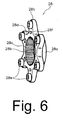
- Fig. 6 is a more detailed view of the rotor attachment boss shown in Fig. 4;
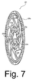
- Fig. 7 is a more detailed view of the disk brake rotor shown in Fig. 4;
- Fig. 8 is a more detailed view of the rotor retaining member in Fig. 4;
- Fig. 9 is a more detailed view of the securing ring shown in Fig. 4;
- Fig. 10 is a view of the disk brake rotor attached to the wheel hub;
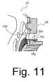
- Fig. 11 is a more detailed view showing the attachment of the disk brake rotor to the rotor attachment boss;
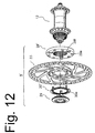
- Fig. 12 is an exploded view of further embodiments of disk brake components associated with a wheel hub; and
- Fig. 13 is an exploded view of another embodiment of a rotor attachment boss.
-
- Fig. 1 is a side view of a particular embodiment of a
bicycle 10.Bicycle 10 comprises aframe 14, afront wheel 13 rotatably connected to a front fork offrame 14 through a frontdisk brake hub 12, a rear wheel 13' rotatably connected to the rear portion offrame 14 through a rear disk brake hub 12', aseat 17 adjustably connected toframe 14,handlebars 18 connected to the front fork for rotatingfront wheel 13, and adrive train 19 for propelling thebicycle 10. A plurality ofspokes 24 extend outwardly from the front and reardisk brake hubs 12 and 12', wherein the outer ends ofspokes 24 are fastened to arim 25 with spoke nipples (not shown) in a conventional manner. Atire 26 is disposed on the outer circumference of eachrim 25.Bicycle 10 and its various parts are well known, so a description thereof shall be omitted, except for the components comprising the front and reardisk brake hubs 12 and 12'. Other components such as other brakes, derailleurs, additional sprockets, etc. may be used withbicycle 10. - As shown in Figs. 2 and 3,
bicycle 10 further comprises front and reardisk brake assemblies 20 and 20', respectively. Eachdisk brake assembly 20 and 21' comprises acaliper 21 mounted to the front fork orframe 14, respectively, abrake lever 22 mounted tohandlebar 18, and adisk brake rotor 23 mounted to its associatedhub 12 or 12'. Since the disk brake assemblies 20 and 20' are substantially the same, only the relevant components ofdisk brake assembly 20 shall be described further. - Fig. 4 is an exploded view of particular embodiments of disk brake components associated with
wheel hub 12. In general,disk brake rotor 23 is detachably and nonrotatably connected todisk brake hub 12 using an adapter in the form of arotor attachment boss 28, a fastener in the form of asecuring ring 29, and arotor retaining member 30.Disk brake rotor 23,rotor attachment boss 28, securingring 29 androtor retaining member 30 comprise a diskbrake rotor assembly 8. As discussed in more detail below,rotor retaining member 30 securesdisk brake rotor 23 to adapter 28 using a finger pressing operation without requiring rivets, bolts or tools. - Front
disk brake hub 12 is nearly identical to the rear disk brake hub 12' except that it lacks a freewheel. As shown in Fig. 5,disk brake hub 12 comprises ahub axle 31, ahub shell 32 rotatably supported onhub axle 31 in a conventional manner, a firstspoke connecting flange 33a, a secondspoke connecting flange 33b, and a brakerotor attachment unit 34. First and secondspoke connecting flanges rotor attachment unit 34 are formed as a unified part withhub shell 32. - First
spoke connecting flange 33a is an annular spoke flange disposed onhub shell 32 at a firsthub shell end 32a ofhub shell 32. A plurality offirst spoke openings 43a are formed circumferentially equidistant in firstspoke connecting flange 33a for receiving the curved ends of some of the plurality ofspokes 24. Similarly, secondspoke connecting flange 33b is an annular spoke flange disposed onhub shell 32 at a secondhub shell end 32b ofhub shell 32. A plurality ofsecond spoke openings 43b are formed circumferentially equidistant in secondspoke connecting flange 33b for receiving the curved ends of other ones of the plurality ofspokes 24. As a result, thespokes 24 extend radially outwardly in a circumferential manner. - Brake
rotor attachment unit 34 is disposed at firsthub shell end 32a ofhub shell 32 adjacent to firstspoke connecting flange 33a. Brakerotor attachment unit 34 comprises atubular member 34a and an annularadjoining flange 34b extending radially outwardly fromtubular member 34a.Tubular member 34a has an outer peripheral surface defining a plurality ofmale splines 34c and an inner peripheral surface defining a female threadedportion 34d. - As shown in Fig. 6,
rotor attachment boss 28 comprises anannular base portion 28a with acenter opening 28b, wherein the inner peripheral surface ofcenter opening 28b defines a plurality offemale splines 28c.Splines 28c are structured to engage the plurality ofsplines 34c on brakerotor attachment unit 34 ofhub 12 so thatrotor attachment boss 28 can be nonrotatably attached tohub 12.Rotor attachment boss 28 further comprises arotor connector 28d that extends radially outwardly frombase portion 28a and defines a plurality of equally spacedrotor attachment arms 28h. Eachrotor attachment arm 28h preferably includes at least one axially extendingprotruding portion 28e and at least one insertion opening 28f for purposes discussed below. As shown in Fig. 11, eachinsertion opening 28f defines a radially extending step 28g. In this embodiment,rotor attachment boss 28 comprises aluminum. - As shown in Fig. 7,
disk brake rotor 23 comprises abraking ring 23a formed with a plurality of openings, a plurality of (e.g., eight) connectingarms 23b disposed circumferentially equidistant and extending radially inwardly from brakingring 23a, and aninner attachment unit 23c connected tangentially to the inner ends of the plurality of connectingarms 23b so that the plurality of connectingarms 23b form a plurality of triangular openings. In this embodiment,braking ring 23a, the plurality of connectingarms 23b andinner attachment unit 23c are one piece.Disk brake rotor 23 preferably is made from stainless steel or some other appropriate material, usually with a specific gravity greater than that of the material formingrotor attachment boss 28, which can withstand braking forces. -
Inner attachment unit 23c comprises a plurality of circumferentiallyequidistant insertion openings 23d, preferably one perinsertion opening 28f inrotor attachment boss 28, a plurality of (e.g., six) circumferentiallyequidistant connection notches 23e, and a plurality of circumferentiallyequidistant connection openings 23g, preferably one per protrudingportion 28e inrotor attachment boss 28. Each protrudingportion 28e inrotor attachment boss 28 engages acorresponding connection opening 23g ininner attachment unit 23c so thatdisk brake rotor 23 may be nonrotatably attached torotor attachment boss 28. The axial length of each protrudingportion 28e preferably is less than or equal to the thickness ofinner attachment unit 23c. - As shown in Fig. 8,
rotor retaining member 30 comprises an annular disk-shapedmain body 30c and a plurality of (e.g., three) elasticallydeformable latching members 30a extending perpendicularly from a lateral side face ofmain body 30c. Each latchingmember 30a includes a radially inwardly curved protrudingportion 30b at the tip thereof. Protrudingportion 30b is structured to engage step 28g ininsertion opening 28f ofrotor attachment boss 28 whenrotor retaining member 30 is attached torotor attachment boss 28. - As shown in Fig. 9, securing
ring 29 comprises anannular flange 29c and atubular portion 29d that extends axially from the inner peripheral surface offlange 29c.Flange 29c includes acentral opening 29a defining a plurality offemale splines 29b that are structured to engage an assembly tool (not shown).Tubular portion 29d includes a male threadedportion 29e structured to engage the female threadedportion 34d on brakerotor attachment unit 34 ofhub 12. Thus, when securingring 29 is screwed into brakerotor attachment unit 34, the side face offlange 29c presses againstmain body 30c ofrotor retaining member 30 which, in turn, presses againstinner attachment unit 23c ofdisk brake rotor 23 which, in turn, presses againstflange 34b of brakerotor attachment unit 34 ofhub 12. - Fig. 10 is a view of disk
brake rotor assembly 8 attached tohub 12, and Fig. 11 is a more detailed view showing howrotor retaining member 30 retainsdisk brake rotor 23 to brakerotor attachment unit 34 ofhub 12. Initially,rotor attachment boss 28 is mounted to brakerotor attachment unit 34 ofhub 12 by engaging themale splines 34c on brakerotor attachment unit 34 with thefemale splines 28c onrotor attachment boss 28. Then,disk brake rotor 23 is placed onrotor attachment boss 28 by engaging protrudingportions 28e ofrotor attachment boss 28 with thecorresponding connection openings 23g indisk brake rotor 23. At this time,insertion openings 23d indisk brake rotor 23 align withinsertion openings 28f inrotor attachment boss 28. - Latching
members 30a ofrotor retaining member 30 then are inserted throughinsertion openings 23d indisk brake rotor 23 and intoinsertion openings 28f ofrotor attachment boss 28. Latchingmembers 30a deflect radially outwardly until projectingportions 30b move radially inwardly to latch onto corresponding steps 28g ininsertion openings 28f. As a result,disk brake rotor 23 is retained torotor attachment boss 28 simply by a single touch pressing operation onrotor retaining member 30. Attaching and tightening bolts are not required, thus greatly simplifying the manufacturing operation and enhancing production efficiency. - Finally, securing
ring 29 is screwed into the female threadedportion 34d of brakerotor attachment unit 34 ofhub 12 to tightly secure diskbrake rotor assembly 8 tohub 12. Thedisk brake rotor 23, sandwiched betweenrotor attachment boss 28 and securingring 29 to form a strong connection, is thereby secured in a non-rotatable state to the brakerotor attachment unit 34 ofhub 12. - When one desires to disassemble disk
brake rotor assembly 8, thestopper 30 is simply pulled in the direction opposite the direction of connection. The latchingmembers 30a then deflect radially outwardly, and thecurved portions 30b of latchingmembers 30a disengage from the steps 28g formed in theinsertion openings 28f ofrotor attachment boss 28. Latchingmembers 30a then may be pulled frominsertion openings 28f ofrotor attachment boss 28 andinsertion openings 23d ofdisk brake rotor 23,disk brake rotor 23 may be removed fromrotor attachment boss 28, androtor attachment boss 28 may be removed from brakerotor attachment unit 34 ofhub 12. - While the above is a description of various embodiments of inventive features, further modifications may be employed without departing from the spirit and scope of the present invention. For example,
disk brake rotor 23 need not be sandwiched betweenrotor retaining member 30 and brakerotor attachment unit 34. Instead,rotor retaining member 30 could be inserted from the right side throughinsertion openings 28f inrotor attachment boss 28, throughinsertion openings 23d indisk brake rotor 23, and latch onto the side surface ofdisk brake rotor 23. Securingring 29 may be omitted in some applications. The teachings herein could be applied to one or bothhubs 12 and 12'. - As shown in Fig. 12, it also is possible to form
serrations 30e on the side surface of a rotor retaining member 30' facing securingring 29 to inhibit loosening of securingring 29 due to vibration or the like. Also, a simple annular rotor attachment boss 28' with protrudingportions 28e' andinsertion openings 28f could be provided. - As shown in FIG. 13, a rotor
attachment boss adapter 28" could be provided, wherein separately formedpins 28i are press fit intoopenings 28j formed in an annularmain body 28h with an undulating outer peripheral surface. - The size, shape, location or orientation of the various components may be changed as desired. Components that are shown directly connected or contacting each other may have intermediate structures disposed between them. Those features that are designated as preferable certainly are not necessary. The functions of one element may be performed by two, and vice versa. The structures and functions of one embodiment may be adopted in another embodiment. It is not necessary for all advantages to be present in a particular embodiment at the same time. Every feature which is unique from the prior art, alone or in combination with other features, also should be considered a separate description of further inventions by the applicant, including the structural and/or functional concepts embodied by such feature(s). Thus, the scope of the invention should not be limited by the specific structures disclosed or the apparent initial focus or emphasis on a particular structure or feature.
Claims (22)
- An apparatus for fixing a bicycle disk brake rotor (23) to a bicycle wheel hub (12), wherein the apparatus comprises:an adapter (28) structured to be nonrotatably coupled to the bicycle wheel hub (12, 12') and to nonrotatably support a disk brake rotor (23), wherein the adapter includes at least one insertion opening (28f); anda rotor retaining member (30) with a latching member (30a) structured to be inserted into the insertion opening (28f) in the adapter (28) to retain the disk brake rotor (23) to the adapter (28).
- The apparatus according to claim 1 wherein the rotor retaining member (30) is structured to support the disk brake rotor (23) between the rotor retaining member (30) and the adapter (28).
- The apparatus according to claim 1 wherein the latching member (30a) comprises an elastically deformable member.
- The apparatus according to claim 1 wherein the latching member (30a) is structured to removably latch the rotor retaining member (30) to the adapter (28).
- The apparatus according to claim 1 further comprising a fastener (29) structured to fasten the rotor retaining member (30) to the bicycle wheel hub (12, 12').
- The apparatus according to claim 1 wherein the rotor retaining member (30) comprises an annular main body (30c), wherein the latching member (30a) extends from the main body (30c).
- The apparatus according to claim 6 wherein the latching member (30a) extends perpendicularly from a lateral side face of the main body (30c).
- The apparatus according to claim 6 wherein the latching member (30a) has a protruding portion (30b) that protrudes radially relative to the latching member (30a).
- The apparatus according to claim 8 wherein the adapter (28) includes a latching structure (28g) that engages the protruding portion (30b) of the latching member (30a).
- The apparatus according to claim 9 wherein the latching structure (28g) is disposed in close proximity to the insertion opening (28f).
- The apparatus according to claim 10 wherein the latching structure (28g) is disposed in the insertion opening (28f).
- The apparatus according to claim 6 wherein the rotor retaining member (30) comprises a plurality of the latching members (30a).
- The apparatus according to claim 12 wherein the rotor retaining member (30) comprises three latching members (30a).
- The apparatus according to claim 1 wherein the adapter (28) includes a protruding portion (28e) structured to be inserted into the disk brake rotor (23).
- The apparatus according to claim 14 wherein the adapter (28) includes a plurality of the protruding portions (28e) structured to be inserted into the disk brake rotor (23) to nonrotatably support the disk brake rotor (23) to the adapter (28).
- The apparatus according to claim 1 wherein the adapter (28) comprises an annular member (28a).
- The apparatus according to claim 16 further comprising a plurality of attachment arms (28h) extending radially outwardly from the annular member (28a).
- The apparatus according to claim 17 wherein each of the plurality of attachment arms (28h) includes a protruding portion (28e) structured to be inserted into the disk brake rotor (23).
- The apparatus according to claim 18 wherein the adapter (28) includes a plurality of the insertion openings (28f), each insertion opening being disposed in close proximity to a corresponding one of the plurality of attachment arms (28h).
- The apparatus according to claim 19 wherein each insertion opening (28f) is disposed radially inwardly from the protruding portion (28e) of the corresponding attachment arm (28h).
- The apparatus according to claim 16 wherein the adapter (28) further comprises a plurality of protruding portions (28e) extending from a lateral side surface of the annular member (28a).
- The apparatus according to claim 21 wherein the adapter (28) includes a plurality of the insertion openings (28f) disposed radially inwardly from the plurality of protruding portions (28e).
Applications Claiming Priority (2)
| Application Number | Priority Date | Filing Date | Title |
|---|---|---|---|
| JP2003433961 | 2003-12-26 | ||
| JP2003433961A JP2005188703A (en) | 2003-12-26 | 2003-12-26 | Disk brake rotor assembly |
Publications (2)
| Publication Number | Publication Date |
|---|---|
| EP1548318A1 true EP1548318A1 (en) | 2005-06-29 |
| EP1548318B1 EP1548318B1 (en) | 2007-04-18 |
Family
ID=34545091
Family Applications (1)
| Application Number | Title | Priority Date | Filing Date |
|---|---|---|---|
| EP04030349A Expired - Lifetime EP1548318B1 (en) | 2003-12-26 | 2004-12-21 | Apparatus for retaining a bicycle disk brake rotor to a bicycle wheel hub |
Country Status (7)
| Country | Link |
|---|---|
| US (1) | US7044272B2 (en) |
| EP (1) | EP1548318B1 (en) |
| JP (1) | JP2005188703A (en) |
| CN (1) | CN1316178C (en) |
| AT (1) | ATE360158T1 (en) |
| DE (1) | DE602004005955T2 (en) |
| TW (1) | TWI259878B (en) |
Cited By (3)
| Publication number | Priority date | Publication date | Assignee | Title |
|---|---|---|---|---|
| EP1847452A3 (en) * | 2006-04-17 | 2008-11-05 | Shimano Inc. | Disc brake rotor retaining assembly |
| EP1760351A3 (en) * | 2005-08-30 | 2008-11-05 | Yamaha Hatsudoki Kabushiki Kaisha | Disk braking device and motorcycle provided with the disk braking device |
| WO2012025604A1 (en) * | 2010-08-26 | 2012-03-01 | Gustav Magenwirth Gmbh & Co. Kg | Master mounting and hydraulic disc brake |
Families Citing this family (28)
| Publication number | Priority date | Publication date | Assignee | Title |
|---|---|---|---|---|
| US7210748B1 (en) * | 2005-03-15 | 2007-05-01 | Isaac Velazquez | Motorcycle hub adapter |
| US20060219488A1 (en) * | 2005-03-29 | 2006-10-05 | Chun-Hsung Chen | Disc brake hub adapter structure |
| US20060284472A1 (en) * | 2005-06-16 | 2006-12-21 | Kun Teng Industry Co., Ltd. | Brakable wheel hub device |
| US20070102246A1 (en) * | 2005-11-10 | 2007-05-10 | Carroll Christopher L | Hub hat for bolt-on brake rotor, associated brake assembly and associated methods |
| US7367632B2 (en) * | 2005-12-14 | 2008-05-06 | Ming Cycle Industrial Co., Ltd. | Hub assembly for disk brake of bicycle |
| US20070158998A1 (en) * | 2006-01-06 | 2007-07-12 | Aron Mathew R | Motorcycle hub adaptor method and apparatus |
| CN101668693B (en) * | 2006-09-14 | 2011-12-14 | 奥蒂斯电梯公司 | Elevator brake with composite brake hub |
| US7909412B2 (en) * | 2007-07-02 | 2011-03-22 | Ashman J Leonard | Cycle wheel mounting system |
| US7695073B1 (en) * | 2007-11-29 | 2010-04-13 | Chosen Co., Ltd. | Bicycle rear hub that is especially available for acrobatics |
| DE102009056075A1 (en) * | 2009-11-30 | 2011-06-09 | Iprotec Maschinen- Und Edelstahlprodukte Gmbh | wheel assembly |
| DE102010040045A1 (en) * | 2010-08-31 | 2012-03-01 | Gustav Magenwirth Gmbh & Co. Kg | Master cylinder for hydraulic disc brake system or clutch system of e.g. bicycle, has connecting device that includes connecting portion for connecting securing element with master cylinder so as to secure cylinder to handlebar |
| DE102010035492A1 (en) * | 2010-08-26 | 2012-03-01 | Gustav Magenwirth Gmbh & Co. Kg | Hydraulic disk brake for e.g. bicycle, has brake disk assembly comprising connecting link for captive connection of brake disk with adapter, where adapter comprises inner toothing for non-rotatable connection with wheel hub |
| KR101196717B1 (en) | 2011-03-28 | 2012-11-06 | 안왕기 | Bicycle front wheel hub |
| US20130240309A1 (en) * | 2011-10-13 | 2013-09-19 | Wayne-Ian Moore | Brake Disk Assembly |
| DE202011052267U1 (en) * | 2011-12-12 | 2013-03-13 | Faiveley Transport Witten Gmbh | Built shaft brake disk |
| CN103434600A (en) * | 2013-07-15 | 2013-12-11 | 温芫鋐 | brake disc |
| US9267560B2 (en) * | 2013-07-31 | 2016-02-23 | Shimano Inc. | Bicycle disc brake rotor assembly and bicycle disc brake rotor |
| JP6104765B2 (en) * | 2013-09-06 | 2017-03-29 | 本田技研工業株式会社 | Vehicle wheel |
| US9878577B2 (en) * | 2013-09-12 | 2018-01-30 | Walther Engineering And Manufacturing Company, Inc. | Hub-rotor adapter |
| CN103953670B (en) * | 2014-05-04 | 2016-09-07 | 宏展五金塑胶制品(苏州)有限公司 | Bicycle disk brake |
| US9334910B2 (en) * | 2014-05-28 | 2016-05-10 | Shimano Inc. | Lock member for fixedly locking a disc brake rotor on a bicycle hub |
| CN104260813A (en) * | 2014-09-23 | 2015-01-07 | 宏展五金塑胶制品(苏州)有限公司 | Safe shaft sleeve for bicycle disc brake and bicycle disc brake |
| US10711857B2 (en) * | 2015-05-14 | 2020-07-14 | Shimano Inc. | Bicycle disc brake rotor |
| IT201600069575A1 (en) * | 2016-07-05 | 2018-01-05 | Campagnolo Srl | Brake disc for bicycle |
| CN114060530A (en) * | 2020-07-31 | 2022-02-18 | 浙江三花智能控制股份有限公司 | Electronic expansion valve |
| DE202023100885U1 (en) | 2022-02-25 | 2023-06-21 | Trickstuff Gmbh | Wheel component with a fixing ring for attaching a brake disc assembly to a bicycle hub |
| US12403981B2 (en) | 2022-03-28 | 2025-09-02 | Trickstuff Gmbh | Wheel component with a fixing ring for attaching a brake disk device to a bicycle hub |
| EP4619296A1 (en) * | 2022-11-15 | 2025-09-24 | 2360216 Ontario Inc. | Disc brake adaptor assembly |
Citations (2)
| Publication number | Priority date | Publication date | Assignee | Title |
|---|---|---|---|---|
| EP1288117A2 (en) * | 2001-08-30 | 2003-03-05 | Shimano Inc. | Bicycle disc brake hub |
| US20040182654A1 (en) * | 2003-03-18 | 2004-09-23 | Hubert Chen | Brakable wheel hub device |
Family Cites Families (4)
| Publication number | Priority date | Publication date | Assignee | Title |
|---|---|---|---|---|
| DE2030503A1 (en) * | 1970-06-20 | 1971-12-30 | Norddeutsche Affinerie, 2000 Hamburg | Extraction of ores - by leaching and regeneration of spent fe-solution by oxidation |
| US6530457B1 (en) * | 1999-12-29 | 2003-03-11 | Shimano, Inc. | Bicycle brake disk with arms connecting an inner annular portion to an outer annular portion and tangent to an effective circle |
| TW553085U (en) * | 2003-01-22 | 2003-09-11 | Kun Teng Industry Co Ltd | Disc brake hub allowing easily assembling and disassembling discs |
| WO2004088162A1 (en) * | 2003-03-28 | 2004-10-14 | Hayes Disc Brakes, Llc | Quick-mount disc brake rotor |
-
2003
- 2003-12-26 JP JP2003433961A patent/JP2005188703A/en active Pending
-
2004
- 2004-04-01 CN CNB2004100321066A patent/CN1316178C/en not_active Expired - Lifetime
- 2004-04-13 TW TW093110258A patent/TWI259878B/en not_active IP Right Cessation
- 2004-12-21 EP EP04030349A patent/EP1548318B1/en not_active Expired - Lifetime
- 2004-12-21 DE DE602004005955T patent/DE602004005955T2/en not_active Expired - Lifetime
- 2004-12-21 AT AT04030349T patent/ATE360158T1/en not_active IP Right Cessation
- 2004-12-22 US US10/905,244 patent/US7044272B2/en not_active Expired - Lifetime
Patent Citations (2)
| Publication number | Priority date | Publication date | Assignee | Title |
|---|---|---|---|---|
| EP1288117A2 (en) * | 2001-08-30 | 2003-03-05 | Shimano Inc. | Bicycle disc brake hub |
| US20040182654A1 (en) * | 2003-03-18 | 2004-09-23 | Hubert Chen | Brakable wheel hub device |
Cited By (7)
| Publication number | Priority date | Publication date | Assignee | Title |
|---|---|---|---|---|
| EP1760351A3 (en) * | 2005-08-30 | 2008-11-05 | Yamaha Hatsudoki Kabushiki Kaisha | Disk braking device and motorcycle provided with the disk braking device |
| CN1924388B (en) * | 2005-08-30 | 2010-06-16 | 雅马哈发动机株式会社 | Disk braking device and motorcycle |
| US7849980B2 (en) | 2005-08-30 | 2010-12-14 | Yamaha Hatsudoki Kabushiki Kaisha | Disk braking device and motorcycle provided with the disk braking device |
| EP1847452A3 (en) * | 2006-04-17 | 2008-11-05 | Shimano Inc. | Disc brake rotor retaining assembly |
| US7665584B2 (en) | 2006-04-17 | 2010-02-23 | Shimano Inc. | Disc rotor retaining assembly |
| WO2012025604A1 (en) * | 2010-08-26 | 2012-03-01 | Gustav Magenwirth Gmbh & Co. Kg | Master mounting and hydraulic disc brake |
| EP3150879A1 (en) * | 2010-08-26 | 2017-04-05 | Gustav Magenwirth GmbH & Co. KG | Hydraulic disc brake |
Also Published As
| Publication number | Publication date |
|---|---|
| CN1637312A (en) | 2005-07-13 |
| JP2005188703A (en) | 2005-07-14 |
| ATE360158T1 (en) | 2007-05-15 |
| TW200521353A (en) | 2005-07-01 |
| TWI259878B (en) | 2006-08-11 |
| DE602004005955T2 (en) | 2007-08-30 |
| EP1548318B1 (en) | 2007-04-18 |
| US7044272B2 (en) | 2006-05-16 |
| DE602004005955D1 (en) | 2007-05-31 |
| US20050139431A1 (en) | 2005-06-30 |
| CN1316178C (en) | 2007-05-16 |
Similar Documents
| Publication | Publication Date | Title |
|---|---|---|
| EP1548318B1 (en) | Apparatus for retaining a bicycle disk brake rotor to a bicycle wheel hub | |
| US7665584B2 (en) | Disc rotor retaining assembly | |
| US7143872B2 (en) | Apparatus for retaining a bicycle disk brake rotor to a bicycle wheel hub | |
| US6371252B1 (en) | Bicycle disc brake hub | |
| US5626401A (en) | Spoked wheel hub | |
| US7216743B2 (en) | Bicycle disc brake rotor assembly | |
| JP3545373B2 (en) | Bicycle hub assembly | |
| US9944119B2 (en) | Hub assembly for a bicycle | |
| JP3619458B2 (en) | Bicycle hub for disc brake | |
| CZ20014361A3 (en) | Bicycle wheel head with a sliding connecting part and a separable freewheel clutch | |
| TW436430B (en) | Hub shell for bicycle | |
| JP3703781B2 (en) | Bicycle disc brake hub | |
| US6976791B2 (en) | Bearing apparatus for a bicycle hub | |
| JP3578718B2 (en) | Bicycle hub for tangent spokes | |
| CN205044904U (en) | A locking component for bicycle part | |
| US6485108B1 (en) | Bicycle hub | |
| CN223865056U (en) | Pressing riveting type lock disc | |
| CN117858807A (en) | Wheel unit for electric power-assisted bicycle and electric power-assisted bicycle | |
| JPS607201Y2 (en) | Spoke mounting structure for motorcycle wheels, etc. | |
| TWM524270U (en) | Locking member for bicycle components |
Legal Events
| Date | Code | Title | Description |
|---|---|---|---|
| PUAI | Public reference made under article 153(3) epc to a published international application that has entered the european phase |
Free format text: ORIGINAL CODE: 0009012 |
|
| AK | Designated contracting states |
Kind code of ref document: A1 Designated state(s): AT BE BG CH CY CZ DE DK EE ES FI FR GB GR HU IE IS IT LI LT LU MC NL PL PT RO SE SI SK TR |
|
| AX | Request for extension of the european patent |
Extension state: AL BA HR LV MK YU |
|
| 17P | Request for examination filed |
Effective date: 20050727 |
|
| AKX | Designation fees paid |
Designated state(s): AT BE BG CH CY CZ DE DK EE ES FI FR GB GR HU IE IS IT LI LT LU MC NL PL PT RO SE SI SK TR |
|
| RAP1 | Party data changed (applicant data changed or rights of an application transferred) |
Owner name: SHIMANO INC. |
|
| GRAP | Despatch of communication of intention to grant a patent |
Free format text: ORIGINAL CODE: EPIDOSNIGR1 |
|
| GRAS | Grant fee paid |
Free format text: ORIGINAL CODE: EPIDOSNIGR3 |
|
| GRAA | (expected) grant |
Free format text: ORIGINAL CODE: 0009210 |
|
| AK | Designated contracting states |
Kind code of ref document: B1 Designated state(s): AT BE BG CH CY CZ DE DK EE ES FI FR GB GR HU IE IS IT LI LT LU MC NL PL PT RO SE SI SK TR |
|
| PG25 | Lapsed in a contracting state [announced via postgrant information from national office to epo] |
Ref country code: LI Free format text: LAPSE BECAUSE OF FAILURE TO SUBMIT A TRANSLATION OF THE DESCRIPTION OR TO PAY THE FEE WITHIN THE PRESCRIBED TIME-LIMIT Effective date: 20070418 Ref country code: FI Free format text: LAPSE BECAUSE OF FAILURE TO SUBMIT A TRANSLATION OF THE DESCRIPTION OR TO PAY THE FEE WITHIN THE PRESCRIBED TIME-LIMIT Effective date: 20070418 Ref country code: CH Free format text: LAPSE BECAUSE OF FAILURE TO SUBMIT A TRANSLATION OF THE DESCRIPTION OR TO PAY THE FEE WITHIN THE PRESCRIBED TIME-LIMIT Effective date: 20070418 Ref country code: SI Free format text: LAPSE BECAUSE OF FAILURE TO SUBMIT A TRANSLATION OF THE DESCRIPTION OR TO PAY THE FEE WITHIN THE PRESCRIBED TIME-LIMIT Effective date: 20070418 |
|
| REG | Reference to a national code |
Ref country code: CH Ref legal event code: EP |
|
| REG | Reference to a national code |
Ref country code: IE Ref legal event code: FG4D |
|
| REF | Corresponds to: |
Ref document number: 602004005955 Country of ref document: DE Date of ref document: 20070531 Kind code of ref document: P |
|
| PG25 | Lapsed in a contracting state [announced via postgrant information from national office to epo] |
Ref country code: SE Free format text: LAPSE BECAUSE OF FAILURE TO SUBMIT A TRANSLATION OF THE DESCRIPTION OR TO PAY THE FEE WITHIN THE PRESCRIBED TIME-LIMIT Effective date: 20070718 |
|
| PG25 | Lapsed in a contracting state [announced via postgrant information from national office to epo] |
Ref country code: ES Free format text: LAPSE BECAUSE OF FAILURE TO SUBMIT A TRANSLATION OF THE DESCRIPTION OR TO PAY THE FEE WITHIN THE PRESCRIBED TIME-LIMIT Effective date: 20070729 |
|
| PG25 | Lapsed in a contracting state [announced via postgrant information from national office to epo] |
Ref country code: IS Free format text: LAPSE BECAUSE OF FAILURE TO SUBMIT A TRANSLATION OF THE DESCRIPTION OR TO PAY THE FEE WITHIN THE PRESCRIBED TIME-LIMIT Effective date: 20070818 |
|
| PG25 | Lapsed in a contracting state [announced via postgrant information from national office to epo] |
Ref country code: PT Free format text: LAPSE BECAUSE OF FAILURE TO SUBMIT A TRANSLATION OF THE DESCRIPTION OR TO PAY THE FEE WITHIN THE PRESCRIBED TIME-LIMIT Effective date: 20070918 |
|
| ET | Fr: translation filed | ||
| REG | Reference to a national code |
Ref country code: CH Ref legal event code: PL |
|
| PG25 | Lapsed in a contracting state [announced via postgrant information from national office to epo] |
Ref country code: PL Free format text: LAPSE BECAUSE OF FAILURE TO SUBMIT A TRANSLATION OF THE DESCRIPTION OR TO PAY THE FEE WITHIN THE PRESCRIBED TIME-LIMIT Effective date: 20070418 Ref country code: AT Free format text: LAPSE BECAUSE OF FAILURE TO SUBMIT A TRANSLATION OF THE DESCRIPTION OR TO PAY THE FEE WITHIN THE PRESCRIBED TIME-LIMIT Effective date: 20070418 |
|
| PG25 | Lapsed in a contracting state [announced via postgrant information from national office to epo] |
Ref country code: BE Free format text: LAPSE BECAUSE OF FAILURE TO SUBMIT A TRANSLATION OF THE DESCRIPTION OR TO PAY THE FEE WITHIN THE PRESCRIBED TIME-LIMIT Effective date: 20070418 |
|
| PG25 | Lapsed in a contracting state [announced via postgrant information from national office to epo] |
Ref country code: BG Free format text: LAPSE BECAUSE OF FAILURE TO SUBMIT A TRANSLATION OF THE DESCRIPTION OR TO PAY THE FEE WITHIN THE PRESCRIBED TIME-LIMIT Effective date: 20070718 Ref country code: DK Free format text: LAPSE BECAUSE OF FAILURE TO SUBMIT A TRANSLATION OF THE DESCRIPTION OR TO PAY THE FEE WITHIN THE PRESCRIBED TIME-LIMIT Effective date: 20070418 Ref country code: CZ Free format text: LAPSE BECAUSE OF FAILURE TO SUBMIT A TRANSLATION OF THE DESCRIPTION OR TO PAY THE FEE WITHIN THE PRESCRIBED TIME-LIMIT Effective date: 20070418 |
|
| PLBE | No opposition filed within time limit |
Free format text: ORIGINAL CODE: 0009261 |
|
| STAA | Information on the status of an ep patent application or granted ep patent |
Free format text: STATUS: NO OPPOSITION FILED WITHIN TIME LIMIT |
|
| PG25 | Lapsed in a contracting state [announced via postgrant information from national office to epo] |
Ref country code: SK Free format text: LAPSE BECAUSE OF FAILURE TO SUBMIT A TRANSLATION OF THE DESCRIPTION OR TO PAY THE FEE WITHIN THE PRESCRIBED TIME-LIMIT Effective date: 20070418 Ref country code: LT Free format text: LAPSE BECAUSE OF FAILURE TO SUBMIT A TRANSLATION OF THE DESCRIPTION OR TO PAY THE FEE WITHIN THE PRESCRIBED TIME-LIMIT Effective date: 20070418 |
|
| 26N | No opposition filed |
Effective date: 20080121 |
|
| PG25 | Lapsed in a contracting state [announced via postgrant information from national office to epo] |
Ref country code: GR Free format text: LAPSE BECAUSE OF FAILURE TO SUBMIT A TRANSLATION OF THE DESCRIPTION OR TO PAY THE FEE WITHIN THE PRESCRIBED TIME-LIMIT Effective date: 20070719 |
|
| PG25 | Lapsed in a contracting state [announced via postgrant information from national office to epo] |
Ref country code: RO Free format text: LAPSE BECAUSE OF FAILURE TO SUBMIT A TRANSLATION OF THE DESCRIPTION OR TO PAY THE FEE WITHIN THE PRESCRIBED TIME-LIMIT Effective date: 20070418 |
|
| PG25 | Lapsed in a contracting state [announced via postgrant information from national office to epo] |
Ref country code: MC Free format text: LAPSE BECAUSE OF NON-PAYMENT OF DUE FEES Effective date: 20071231 |
|
| PG25 | Lapsed in a contracting state [announced via postgrant information from national office to epo] |
Ref country code: IE Free format text: LAPSE BECAUSE OF NON-PAYMENT OF DUE FEES Effective date: 20071221 |
|
| PG25 | Lapsed in a contracting state [announced via postgrant information from national office to epo] |
Ref country code: EE Free format text: LAPSE BECAUSE OF FAILURE TO SUBMIT A TRANSLATION OF THE DESCRIPTION OR TO PAY THE FEE WITHIN THE PRESCRIBED TIME-LIMIT Effective date: 20070418 |
|
| PG25 | Lapsed in a contracting state [announced via postgrant information from national office to epo] |
Ref country code: CY Free format text: LAPSE BECAUSE OF FAILURE TO SUBMIT A TRANSLATION OF THE DESCRIPTION OR TO PAY THE FEE WITHIN THE PRESCRIBED TIME-LIMIT Effective date: 20070418 |
|
| GBPC | Gb: european patent ceased through non-payment of renewal fee |
Effective date: 20081221 |
|
| PG25 | Lapsed in a contracting state [announced via postgrant information from national office to epo] |
Ref country code: LU Free format text: LAPSE BECAUSE OF NON-PAYMENT OF DUE FEES Effective date: 20071221 |
|
| PG25 | Lapsed in a contracting state [announced via postgrant information from national office to epo] |
Ref country code: HU Free format text: LAPSE BECAUSE OF FAILURE TO SUBMIT A TRANSLATION OF THE DESCRIPTION OR TO PAY THE FEE WITHIN THE PRESCRIBED TIME-LIMIT Effective date: 20071019 Ref country code: TR Free format text: LAPSE BECAUSE OF FAILURE TO SUBMIT A TRANSLATION OF THE DESCRIPTION OR TO PAY THE FEE WITHIN THE PRESCRIBED TIME-LIMIT Effective date: 20070418 |
|
| PG25 | Lapsed in a contracting state [announced via postgrant information from national office to epo] |
Ref country code: GB Free format text: LAPSE BECAUSE OF NON-PAYMENT OF DUE FEES Effective date: 20081221 |
|
| PGFP | Annual fee paid to national office [announced via postgrant information from national office to epo] |
Ref country code: FR Payment date: 20131209 Year of fee payment: 10 Ref country code: NL Payment date: 20131109 Year of fee payment: 10 |
|
| REG | Reference to a national code |
Ref country code: NL Ref legal event code: V1 Effective date: 20150701 |
|
| REG | Reference to a national code |
Ref country code: NL Ref legal event code: V1 Effective date: 20150701 |
|
| REG | Reference to a national code |
Ref country code: FR Ref legal event code: ST Effective date: 20150831 |
|
| PG25 | Lapsed in a contracting state [announced via postgrant information from national office to epo] |
Ref country code: NL Free format text: LAPSE BECAUSE OF NON-PAYMENT OF DUE FEES Effective date: 20150701 |
|
| PG25 | Lapsed in a contracting state [announced via postgrant information from national office to epo] |
Ref country code: FR Free format text: LAPSE BECAUSE OF NON-PAYMENT OF DUE FEES Effective date: 20141231 |
|
| PGFP | Annual fee paid to national office [announced via postgrant information from national office to epo] |
Ref country code: IT Payment date: 20151221 Year of fee payment: 12 |
|
| PG25 | Lapsed in a contracting state [announced via postgrant information from national office to epo] |
Ref country code: IT Free format text: LAPSE BECAUSE OF NON-PAYMENT OF DUE FEES Effective date: 20161221 |
|
| PGFP | Annual fee paid to national office [announced via postgrant information from national office to epo] |
Ref country code: DE Payment date: 20220622 Year of fee payment: 19 |
|
| P01 | Opt-out of the competence of the unified patent court (upc) registered |
Effective date: 20230428 |
|
| REG | Reference to a national code |
Ref country code: DE Ref legal event code: R119 Ref document number: 602004005955 Country of ref document: DE |
|
| PG25 | Lapsed in a contracting state [announced via postgrant information from national office to epo] |
Ref country code: DE Free format text: LAPSE BECAUSE OF NON-PAYMENT OF DUE FEES Effective date: 20240702 |
|
| PG25 | Lapsed in a contracting state [announced via postgrant information from national office to epo] |
Ref country code: DE Free format text: LAPSE BECAUSE OF NON-PAYMENT OF DUE FEES Effective date: 20240702 |